EP0505171B1 - Condensate collector - Google Patents
Condensate collector Download PDFInfo
- Publication number
- EP0505171B1 EP0505171B1 EP92302346A EP92302346A EP0505171B1 EP 0505171 B1 EP0505171 B1 EP 0505171B1 EP 92302346 A EP92302346 A EP 92302346A EP 92302346 A EP92302346 A EP 92302346A EP 0505171 B1 EP0505171 B1 EP 0505171B1
- Authority
- EP
- European Patent Office
- Prior art keywords
- grooves
- condensate
- condensate collector
- lid
- facing portion
- Prior art date
- Legal status (The legal status is an assumption and is not a legal conclusion. Google has not performed a legal analysis and makes no representation as to the accuracy of the status listed.)
- Expired - Lifetime
Links
- XLYOFNOQVPJJNP-UHFFFAOYSA-N water Substances O XLYOFNOQVPJJNP-UHFFFAOYSA-N 0.000 claims abstract description 10
- 239000004033 plastic Substances 0.000 claims description 8
- 229920003023 plastic Polymers 0.000 claims description 8
- 235000013305 food Nutrition 0.000 claims description 7
- 239000000463 material Substances 0.000 claims description 7
- 230000015572 biosynthetic process Effects 0.000 claims description 4
- 235000013311 vegetables Nutrition 0.000 abstract description 20
- 235000013399 edible fruits Nutrition 0.000 abstract description 8
- 238000004140 cleaning Methods 0.000 description 3
- 230000005484 gravity Effects 0.000 description 3
- 238000000576 coating method Methods 0.000 description 2
- 238000002474 experimental method Methods 0.000 description 2
- 239000011358 absorbing material Substances 0.000 description 1
- 238000009825 accumulation Methods 0.000 description 1
- 239000011248 coating agent Substances 0.000 description 1
- 238000009833 condensation Methods 0.000 description 1
- 230000005494 condensation Effects 0.000 description 1
- 238000010276 construction Methods 0.000 description 1
- 239000003599 detergent Substances 0.000 description 1
- 235000012055 fruits and vegetables Nutrition 0.000 description 1
- 239000011521 glass Substances 0.000 description 1
- 238000001746 injection moulding Methods 0.000 description 1
- 239000004922 lacquer Substances 0.000 description 1
- 238000011068 loading method Methods 0.000 description 1
- 239000002184 metal Substances 0.000 description 1
- 230000002093 peripheral effect Effects 0.000 description 1
- 230000000717 retained effect Effects 0.000 description 1
- 238000007666 vacuum forming Methods 0.000 description 1
Images

Classifications
-
- F—MECHANICAL ENGINEERING; LIGHTING; HEATING; WEAPONS; BLASTING
- F25—REFRIGERATION OR COOLING; COMBINED HEATING AND REFRIGERATION SYSTEMS; HEAT PUMP SYSTEMS; MANUFACTURE OR STORAGE OF ICE; LIQUEFACTION SOLIDIFICATION OF GASES
- F25D—REFRIGERATORS; COLD ROOMS; ICE-BOXES; COOLING OR FREEZING APPARATUS NOT OTHERWISE PROVIDED FOR
- F25D21/00—Defrosting; Preventing frosting; Removing condensed or defrost water
- F25D21/14—Collecting or removing condensed and defrost water; Drip trays
-
- F—MECHANICAL ENGINEERING; LIGHTING; HEATING; WEAPONS; BLASTING
- F25—REFRIGERATION OR COOLING; COMBINED HEATING AND REFRIGERATION SYSTEMS; HEAT PUMP SYSTEMS; MANUFACTURE OR STORAGE OF ICE; LIQUEFACTION SOLIDIFICATION OF GASES
- F25D—REFRIGERATORS; COLD ROOMS; ICE-BOXES; COOLING OR FREEZING APPARATUS NOT OTHERWISE PROVIDED FOR
- F25D25/00—Charging, supporting, and discharging the articles to be cooled
- F25D25/02—Charging, supporting, and discharging the articles to be cooled by shelves
- F25D25/024—Slidable shelves
- F25D25/025—Drawers
-
- F—MECHANICAL ENGINEERING; LIGHTING; HEATING; WEAPONS; BLASTING
- F25—REFRIGERATION OR COOLING; COMBINED HEATING AND REFRIGERATION SYSTEMS; HEAT PUMP SYSTEMS; MANUFACTURE OR STORAGE OF ICE; LIQUEFACTION SOLIDIFICATION OF GASES
- F25D—REFRIGERATORS; COLD ROOMS; ICE-BOXES; COOLING OR FREEZING APPARATUS NOT OTHERWISE PROVIDED FOR
- F25D2321/00—Details or arrangements for defrosting; Preventing frosting; Removing condensed or defrost water, not provided for in other groups of this subclass
- F25D2321/14—Collecting condense or defrost water; Removing condense or defrost water
- F25D2321/144—Collecting condense or defrost water; Removing condense or defrost water characterised by the construction of drip water collection pans
- F25D2321/1441—Collecting condense or defrost water; Removing condense or defrost water characterised by the construction of drip water collection pans inside a refrigerator
-
- F—MECHANICAL ENGINEERING; LIGHTING; HEATING; WEAPONS; BLASTING
- F25—REFRIGERATION OR COOLING; COMBINED HEATING AND REFRIGERATION SYSTEMS; HEAT PUMP SYSTEMS; MANUFACTURE OR STORAGE OF ICE; LIQUEFACTION SOLIDIFICATION OF GASES
- F25D—REFRIGERATORS; COLD ROOMS; ICE-BOXES; COOLING OR FREEZING APPARATUS NOT OTHERWISE PROVIDED FOR
- F25D2321/00—Details or arrangements for defrosting; Preventing frosting; Removing condensed or defrost water, not provided for in other groups of this subclass
- F25D2321/14—Collecting condense or defrost water; Removing condense or defrost water
- F25D2321/147—Collecting condense or defrost water; Removing condense or defrost water characterised by capillary, wick, adsorbent, or evaporation elements
-
- F—MECHANICAL ENGINEERING; LIGHTING; HEATING; WEAPONS; BLASTING
- F25—REFRIGERATION OR COOLING; COMBINED HEATING AND REFRIGERATION SYSTEMS; HEAT PUMP SYSTEMS; MANUFACTURE OR STORAGE OF ICE; LIQUEFACTION SOLIDIFICATION OF GASES
- F25D—REFRIGERATORS; COLD ROOMS; ICE-BOXES; COOLING OR FREEZING APPARATUS NOT OTHERWISE PROVIDED FOR
- F25D2500/00—Problems to be solved
- F25D2500/02—Geometry problems
Definitions
- This invention relates to a condensate collector as defined in the preamble of claim 1.
- a condensate collector is known, for instance, from US-A-2 670 611.
- the collector of the invention has been designed particularly though not necessarily solely for use in association with a refrigerator fruit or vegetable bin.
- Vegetables and fruit are often kept in a lidded food compartment in a refrigerator. As these vegetables and fruit are generally still respiring, the water produced may cause water droplets to condense and form on the cold upper surface of the vegetable bin lid. These droplets are then able to fall back onto the fruit and vegetables thus resulting in rotting and spoilage thereof. This is disadvantageous.
- US Patent 2 670 611 seeks to overcome the problem of dripping condensation by provision of a condensate collector.
- the condensate collector has two substantially horizontal plates which have a downward inclination of between 8° and 11° toward a moisture collecting trough. It is also envisaged in this specification that these plates may be ribbed or otherwise channelled to direct the running drops as they flow towards this collection trough.
- Such a simple incline surface works adequately with metal or even glass materials, which have inherent drop forming capabilities and surface adhesion, but it has been found that the water adhesion to plastic surfaces is inadequate to oppose gravity and the droplets tend to fall from the surface rather than flow across the surface.
- German Patent specification DE-B-1 006 441, Brown, Boveri also considers the issue of condensate collection on the underside of surfaces.
- This specification proposes to overcome this difficulty by inclusion of means on the underside surface to improve the adhesion of water vapour thereto.
- the specification includes as an example use of absorbing materials such as blotting paper, a surface coating lacquer or provision of capillary channels. The formation of condensate collection surfaces with such coatings or narrow capillary channels as set forth in this specification would be difficult and/or costly.
- the invention consists in a condensate collector comprising a member having a downwardly facing portion disposed substantially horizontally in use and having a plurality of spaced apart, drainable elongate grooves on said downwardly facing portion, each of said grooves being defined by a pair of side walls connected at their distal ends by a base adjacent said downwardly facing portion, said grooves being disposed at an angle relative to horizontal such that said condensate, accumulated in said grooves, can drain to a draining means positioned on said downwardly facing portion of said member for the purpose of receiving any condensate accumulated in said grooves, characterised in that said member is plastic and, said walls of said grooves are arranged in substantially inverted V-shaped formation wherein the angle between said walls of said V-shape is between about 15° and about 30° and the distance between the proximal ends of said side walls is between about 1.6mm and about 2.8mm such that condensate collecting on said portion migrates to the bases of said grooves by capillary action.
- the invention consists in a lidded food compartment for use in a refrigerator comprising a container and a lid positionable over said container, said lid including a condensate collector as set forth in the above paragraph.
- the invention consists in a cover of a self supporting material capable of stable location over foodstuffs positioned on a supporting surface or tray, said cover including a condensate collector as set forth in the above paragraph.
- the invention consists, in combination, in a tray onto which a foodstuff can be positioned, and a cover positionable over a foodstuff positioned on the tray, said cover being of a self supporting material and being capable of stable location over said tray, said cover including a condensate collector as set forth in the above paragraph.
- the invention relates to a condensate collector.
- the condensate collector can be used in any situation where condensate is formed and it is desirable to remove the condensate to a selected area.
- the condensate collector comprises a lid or cover 1 being positionable over a food container (such as a vegetable bin 2) in a refrigerator 24.
- a food container such as a vegetable bin 2
- a refrigerator 24 In the embodiment of Fig 5, two vegetable/fruit bins 2 are shown. Of course, a single tray or bin 2 could be provided.
- the lid or cover 1 is formed from plastics material.
- the condensate collector has a member 3 defining a downwardly facing portion 4 and is disposed substantially horizontally in use.
- a shelf 5 is provided in the refrigerator 24 and the lid or cover 1 can be affixed to the shelf 5 via loose hooks 6.
- Flat portions 7 may be provided at the front edge 20 and side edges 19 of the lid or cover 1. These portions 7 are able to rest on the peripheral edge of the food container 2.
- the lid or cover 1 is lifted slightly (by about 1mm for example) and this creates a seal, though imperfect, between the vegetable bin 2 and the portions 7 of the lid or cover 1.
- the lid 1 can be formed so as to be substantially engageable with the vegetable bin 2.
- the condensate collector has a plurality of spaced apart, drainable elongate grooves or channels 9 on the downwardly facing portion 4 thereof.
- the grooves 8 are positioned substantially side-by-side.
- the grooves or channels 9 may be provided in a rectangular pattern or in a circular pattern on the downwardly facing portion 4 of the lid 1.
- Figs 2 & 3 show one preferred embodiment of the invention wherein the grooves 9 can be formed in plastic by vacuum forming.
- the grooves 9 have an upwardly disposed base 10 and a pair of side walls 11 extending downwardly from the base 10.
- the cross sectional width A of the upwardly disposed base 10 is preferably less than the distance B between the distal ends of the side walls 11.
- the distance B is in the range between about 1.6mm and about 2.8mm so that a droplet of water is able to be retained in the groove or channel 9 and will not tend to be displaced downwardly by gravity.
- the distance A may for example be between about 1.5mm and 2.5mm in the embodiment of Fig 2 & 3.
- the downwardly extending ridges or junctions 12 between adjacent grooves 9 may form part of the downwardly facing portion 4.
- small droplets of condensate forming on the ridges 12 tend to be drawn into the channels 9 and towards the upwardly disposed bases 10 thereof by water tension. It is desirable to maximise the area of plastic available in the channel 9 so that the condensate will be drawn therein under water tension.
- the angle C between side walls 11 of adjacent grooves 9 is between about 15° and 30°.
- the angle C is about 25°.
- Fig 4 shows an alternative form of the invention.
- This shows a plurality of adjacent channels 9 which may be formed in plastic by injection moulding for example.
- the side walls 11 of the channels 9 are arranged in substantially inverted V-shaped formation.
- the angle D between the walls 11 of the V-shape is between 15 and 30° and is preferably 25°.
- the internal apex of the V-shape or upwardly disposed base 10 of the groove 9 may have an extended surface area wherein the extended surface area can comprise a flat surface blended into the walls 11 of the grooves 9 or can comprise a curved surface of substantially semi-circular shape. This facilitates ease of cleaning the channels 9.
- the junctions 12 may be of radiused or planar shapes as this reduces the risk of physical damage to the thin sections between the channels 9.
- the depth E of the inverted V-shape may be between about 1mm to about 4mm.
- the distance F depends on the angle D and depth E chosen.
- the dimensions, spacings and disposition of the grooves 9 are such that condensate collecting on the downwardly facing portion 4 as well as the walls 11 of the grooves 9 tends to migrate to the upwardly disposed bases 10 of the grooves 9 under water tension.
- the grooves 9 are provided at a slight angle relative to horizontal when positioned over the food bin 2.
- the lid 1 may be constructed such that the tilt of the grooves 3 is a small angle of between about 2-3°. Therefore, any accumulation of condensate in the grooves 9 can be drained in use to a draining area under gravity.
- the draining area may be formed on a downwardly extending portion of the lid 1.
- a downwardly extending baffle 13 may be provided which extends transversely to the grooves 9.
- the length of each groove 9 is longer than the length of the bin 2 from the front face 21 to the rear face 22 thereof (by about 10% for example).
- the ends of the grooves 9 in the overlapping area 14 extend away from the open area of the bin 2 so droplets do not fall on food located in the bin 2.
- the side walls 19 of the lid 1 may taper from the overlapping area 14 to the front edge 20 of the lid 1.
- the front wall 21 of the bin 2 may similarly be longer than the rear wall 22 of the bin 2.
- a locating member 23 may be provided in the refrigerator 24 to locate the vegetable bin 2 in the designed disposition.
- the loose hooks 6 hold the lid 1 in the required disposition such that the grooves 9 are provided on a slight tilt towards the rear inside face of the refrigerator 24. Accordingly, condensate forming a result of vegetables or fruit in the bin 2 respiring is collected in the channels 9 and can slowly drain to the draining area 13 where it can evaporate or drain to the back of the refrigerator 24.
- the lid 1 may normally be provided horizontally and may be manually tilted so as to drain the condensate from the grooves 9 and the lid 1 can then be removed for cleaning.
- a condensate collector which, surprisingly, can store substantial amounts of condensate formed when, for example, vegetables or fruit contained within a vegetable bin in a refrigerator respire.
- the condensate collector can be made self-draining which is desirable.
Landscapes
- Engineering & Computer Science (AREA)
- General Engineering & Computer Science (AREA)
- Combustion & Propulsion (AREA)
- Physics & Mathematics (AREA)
- Mechanical Engineering (AREA)
- Thermal Sciences (AREA)
- Chemical & Material Sciences (AREA)
- Removal Of Water From Condensation And Defrosting (AREA)
- Superconductors And Manufacturing Methods Therefor (AREA)
- Apparatus For Radiation Diagnosis (AREA)
- Bipolar Transistors (AREA)
- Solid-Sorbent Or Filter-Aiding Compositions (AREA)
- Cold Air Circulating Systems And Constructional Details In Refrigerators (AREA)
Abstract
Description
- This invention relates to a condensate collector as defined in the preamble of
claim 1. Such a condensate collector is known, for instance, from US-A-2 670 611. The collector of the invention has been designed particularly though not necessarily solely for use in association with a refrigerator fruit or vegetable bin. - Vegetables and fruit are often kept in a lidded food compartment in a refrigerator. As these vegetables and fruit are generally still respiring, the water produced may cause water droplets to condense and form on the cold upper surface of the vegetable bin lid. These droplets are then able to fall back onto the fruit and vegetables thus resulting in rotting and spoilage thereof. This is disadvantageous.
- US
Patent 2 670 611, Fagerberg et al, seeks to overcome the problem of dripping condensation by provision of a condensate collector. The condensate collector has two substantially horizontal plates which have a downward inclination of between 8° and 11° toward a moisture collecting trough. It is also envisaged in this specification that these plates may be ribbed or otherwise channelled to direct the running drops as they flow towards this collection trough. Such a simple incline surface works adequately with metal or even glass materials, which have inherent drop forming capabilities and surface adhesion, but it has been found that the water adhesion to plastic surfaces is inadequate to oppose gravity and the droplets tend to fall from the surface rather than flow across the surface. - German Patent specification DE-B-1 006 441, Brown, Boveri, also considers the issue of condensate collection on the underside of surfaces. This specification proposes to overcome this difficulty by inclusion of means on the underside surface to improve the adhesion of water vapour thereto. The specification includes as an example use of absorbing materials such as blotting paper, a surface coating lacquer or provision of capillary channels. The formation of condensate collection surfaces with such coatings or narrow capillary channels as set forth in this specification would be difficult and/or costly.
- It is an object of the foregoing invention to provide an apparatus which will go at least some way to obviating or minimizing the foregoing disadvantages in a simple yet effective manner or which will at least provide the public with a useful choice.
- Accordingly, the invention consists in a condensate collector comprising a member having a downwardly facing portion disposed substantially horizontally in use and having a plurality of spaced apart, drainable elongate grooves on said downwardly facing portion, each of said grooves being defined by a pair of side walls connected at their distal ends by a base adjacent said downwardly facing portion, said grooves being disposed at an angle relative to horizontal such that said condensate, accumulated in said grooves, can drain to a draining means positioned on said downwardly facing portion of said member for the purpose of receiving any condensate accumulated in said grooves, characterised in that said member is plastic and, said walls of said grooves are arranged in substantially inverted V-shaped formation wherein the angle between said walls of said V-shape is between about 15° and about 30° and the distance between the proximal ends of said side walls is between about 1.6mm and about 2.8mm such that condensate collecting on said portion migrates to the bases of said grooves by capillary action.
- In a second aspect, the invention consists in a lidded food compartment for use in a refrigerator comprising a container and a lid positionable over said container, said lid including a condensate collector as set forth in the above paragraph.
- In a further aspect the invention consists in a cover of a self supporting material capable of stable location over foodstuffs positioned on a supporting surface or tray, said cover including a condensate collector as set forth in the above paragraph.
- In a yet further aspect, the invention consists, in combination, in a tray onto which a foodstuff can be positioned, and a cover positionable over a foodstuff positioned on the tray, said cover being of a self supporting material and being capable of stable location over said tray, said cover including a condensate collector as set forth in the above paragraph.
- To those skilled in the art to which the invention relates, many changes in construction and widely differing embodiments and applications of the invention will suggest themselves without departing from the scope of the invention as defined in the appended
claim 1. The disclosures and the descriptions herein are purely illustrative and are not intended to be in any sense limiting. - The preferred form of the invention will now be described with reference to the accompanying drawings wherein:
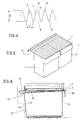
- Fig 1 is a perpective view of a condensate collector in the form of a lid positionable over a vegetable bin according to one preferred form of the invention;
- Fig 2 is a sectional end view through BB of the lid shown in Fig 1;
- Fig 3 is an exploded view of the area X in Fig 2;
- Fig 4 is a schematic drawing of a series of grooves according to an alternative preferred form of the invention; and
- Fig 5 is a perspective view of a lid positioned over a vegetable bin according to one preferred embodiment of the invention, and;
- Fig 6 is a cross sectional side view of the vegetable bin and lid of Fig 6 when located in a refrigerator according to one preferred form of the invention.
- The invention relates to a condensate collector. The condensate collector can be used in any situation where condensate is formed and it is desirable to remove the condensate to a selected area.
- In the preferred embodiment of the invention however, the condensate collector comprises a lid or
cover 1 being positionable over a food container (such as a vegetable bin 2) in arefrigerator 24. In the embodiment of Fig 5, two vegetable/fruit bins 2 are shown. Of course, a single tray orbin 2 could be provided. - The lid or
cover 1 is formed from plastics material. - The condensate collector has a
member 3 defining a downwardly facingportion 4 and is disposed substantially horizontally in use. In the preferred embodiment of the invention, ashelf 5 is provided in therefrigerator 24 and the lid orcover 1 can be affixed to theshelf 5 vialoose hooks 6.Flat portions 7 may be provided at thefront edge 20 andside edges 19 of the lid orcover 1. Theseportions 7 are able to rest on the peripheral edge of thefood container 2. In this embodiment, when thevegetable bin 2 is pushed under the lid or cover 1 the lid orcover 1 is lifted slightly (by about 1mm for example) and this creates a seal, though imperfect, between thevegetable bin 2 and theportions 7 of the lid orcover 1. - Alternatively, the
lid 1 can be formed so as to be substantially engageable with thevegetable bin 2. - The condensate collector has a plurality of spaced apart, drainable elongate grooves or
channels 9 on the downwardly facingportion 4 thereof. Desirably, the grooves 8 are positioned substantially side-by-side. In alternative embodiments of the invention, however, the grooves orchannels 9 may be provided in a rectangular pattern or in a circular pattern on the downwardly facingportion 4 of thelid 1. - Figs 2 & 3 show one preferred embodiment of the invention wherein the
grooves 9 can be formed in plastic by vacuum forming. Thegrooves 9 have an upwardly disposedbase 10 and a pair ofside walls 11 extending downwardly from thebase 10. The cross sectional width A of the upwardly disposedbase 10 is preferably less than the distance B between the distal ends of theside walls 11. - The distance B is in the range between about 1.6mm and about 2.8mm so that a droplet of water is able to be retained in the groove or
channel 9 and will not tend to be displaced downwardly by gravity. The distance A may for example be between about 1.5mm and 2.5mm in the embodiment of Fig 2 & 3. - The downwardly extending ridges or
junctions 12 betweenadjacent grooves 9 may form part of the downwardly facingportion 4. In experiments conducted to date it has been found that small droplets of condensate forming on theridges 12 tend to be drawn into thechannels 9 and towards the upwardly disposedbases 10 thereof by water tension. It is desirable to maximise the area of plastic available in thechannel 9 so that the condensate will be drawn therein under water tension. - In the embodiment of Fig 3, the angle C between
side walls 11 ofadjacent grooves 9 is between about 15° and 30°. Preferably, the angle C is about 25°. - Fig 4 shows an alternative form of the invention. This shows a plurality of
adjacent channels 9 which may be formed in plastic by injection moulding for example. In this embodiment, theside walls 11 of thechannels 9 are arranged in substantially inverted V-shaped formation. The angle D between thewalls 11 of the V-shape is between 15 and 30° and is preferably 25°. The internal apex of the V-shape or upwardly disposedbase 10 of thegroove 9 may have an extended surface area wherein the extended surface area can comprise a flat surface blended into thewalls 11 of thegrooves 9 or can comprise a curved surface of substantially semi-circular shape. This facilitates ease of cleaning thechannels 9. Thejunctions 12 may be of radiused or planar shapes as this reduces the risk of physical damage to the thin sections between thechannels 9. - In the embodiment of Fig 4, to increase the potential condensate loadings in the
grooves 9 it is desirable to have a greater depth E of the inverted V-shape than the distance F between the distal ends of theside walls 11 such that a given volume of condensate is exposed to a large surface area of plastic material which reduces the tendency of drops to form and escape from thegrooves 9. For example, the depth E of the inverted V-shape may be between about 1mm to about 4mm. The distance F, of course, depends on the angle D and depth E chosen. - The dimensions, spacings and disposition of the
grooves 9 are such that condensate collecting on the downwardly facingportion 4 as well as thewalls 11 of thegrooves 9 tends to migrate to the upwardly disposedbases 10 of thegrooves 9 under water tension. - The
grooves 9 are provided at a slight angle relative to horizontal when positioned over thefood bin 2. For example, thelid 1 may be constructed such that the tilt of thegrooves 3 is a small angle of between about 2-3°. Therefore, any accumulation of condensate in thegrooves 9 can be drained in use to a draining area under gravity. The draining area may be formed on a downwardly extending portion of thelid 1. For example, a downwardly extendingbaffle 13 may be provided which extends transversely to thegrooves 9. Desirably, the length of eachgroove 9 is longer than the length of thebin 2 from thefront face 21 to therear face 22 thereof (by about 10% for example). Thus, the ends of thegrooves 9 in the overlappingarea 14 extend away from the open area of thebin 2 so droplets do not fall on food located in thebin 2. - Many different ways of providing the grooves or
channels 9 at a slight angle relative to horizontal are envisaged. The embodiment shown in Fig 6 is just one of these. As shown in Fig 6, theside walls 19 of thelid 1 may taper from the overlappingarea 14 to thefront edge 20 of thelid 1. Thefront wall 21 of thebin 2 may similarly be longer than therear wall 22 of thebin 2. A locatingmember 23 may be provided in therefrigerator 24 to locate thevegetable bin 2 in the designed disposition. Theloose hooks 6 hold thelid 1 in the required disposition such that thegrooves 9 are provided on a slight tilt towards the rear inside face of therefrigerator 24. Accordingly, condensate forming a result of vegetables or fruit in thebin 2 respiring is collected in thechannels 9 and can slowly drain to the drainingarea 13 where it can evaporate or drain to the back of therefrigerator 24. - Alternative means for draining condensate from the
grooves 3 are clearly envisaged. For example, thelid 1 may normally be provided horizontally and may be manually tilted so as to drain the condensate from thegrooves 9 and thelid 1 can then be removed for cleaning. - Experiments conducted to date indicate that, after cleaning with detergent. the ability of the
grooves 9 to hold condensate is enhanced. - Thus it can be seen that in at least the preferred form of the invention a condensate collector is provided which, surprisingly, can store substantial amounts of condensate formed when, for example, vegetables or fruit contained within a vegetable bin in a refrigerator respire. The condensate collector can be made self-draining which is desirable.
Claims (7)
- A condensate collector comprising a member (3) having a downwardly facing portion (4) disposed substantially horizontally in use and having a plurality of spaced apart, drainable elongate grooves (9) on said downwardly facing portion (4), each of said grooves (9) being defined by a pair of side walls (11) connected at their proximal ends by a base (10) adjacent said downwardly facing portion (4), said grooves (9) being disposed at an angle relative to horizontal such that said condensate, accumulated in said grooves (9), can drain to a draining means (13) positioned on said downwardly facing portion (4) of said member (3) for the purpose of receiving any condensate accumulated in said grooves (9), characterised in that said condensate collector is made of plastic and, said pairs of walls (11) of said grooves (9) are arranged in substantially inverted V-shaped formation wherein the angle (C, D) between said walls (11) of said V-shape is between about 15° and about 30° and the distance (B, F) between the distal ends of said side walls (11) is between about 1.6mm and about 2.8mm such that condensate collecting on said portion (4) migrates to the bases (10) of said grooves (9) by capillary action.
- A condensate collector as claimed in claim 1 wherein the junctions (12) of side walls (11) from adjacent grooves (9) are of shapes selected from radiused and planar shapes such that the tendency of water droplets to form at said junctions (12) is reduced.
- A condensate collector as claimed in claim 1 or claim 2 wherein the base (10) of said V-shape has an extended surface area, wherein said extended surface area is selected from a flat surface blended into said walls (11) of said grooves (9) and a curved surface of substantially semi-circular shape.
- A condensate collector as claimed in claim 1 or claim 2 wherein said grooves (9) are inclined at an angle between about 2° and about 3° relative to horizontal.
- A lidded food compartment for use in a refrigerator comprising a container and a lid positionable over said container, said lid including a condensate collector as claimed in any one of claims 1 to 4.
- A cover of a self supporting material capable of stable location over foodstuffs positioned on a supporting surface or tray, said cover including a condensate collector as claimed in any one of claims 1 to 4.
- In combination, a tray onto which a foodstuff can be positioned, and a cover positionable over a foodstuff positioned on the tray, said cover being of a self supporting material and being capable of stable location over said tray, said cover including a condensate collector as claimed in any one of claims 1 to 4.
Applications Claiming Priority (2)
| Application Number | Priority Date | Filing Date | Title |
|---|---|---|---|
| NZ237482 | 1991-03-19 | ||
| NZ237482A NZ237482A (en) | 1991-03-19 | 1991-03-19 | Condensate collector tray with v-shaped grooves |
Publications (3)
| Publication Number | Publication Date |
|---|---|
| EP0505171A2 EP0505171A2 (en) | 1992-09-23 |
| EP0505171A3 EP0505171A3 (en) | 1993-01-13 |
| EP0505171B1 true EP0505171B1 (en) | 1997-06-04 |
Family
ID=19923535
Family Applications (1)
| Application Number | Title | Priority Date | Filing Date |
|---|---|---|---|
| EP92302346A Expired - Lifetime EP0505171B1 (en) | 1991-03-19 | 1992-03-18 | Condensate collector |
Country Status (6)
| Country | Link |
|---|---|
| EP (1) | EP0505171B1 (en) |
| JP (1) | JPH0571856A (en) |
| AT (1) | ATE154121T1 (en) |
| AU (1) | AU653790B2 (en) |
| DE (1) | DE69220117T2 (en) |
| NZ (1) | NZ237482A (en) |
Cited By (2)
| Publication number | Priority date | Publication date | Assignee | Title |
|---|---|---|---|---|
| RU2218528C2 (en) * | 1999-09-03 | 2003-12-10 | Эл Джи Электроникс Инк. | Compartment for vegetables in freezer (variants) |
| CN102235788A (en) * | 2011-08-11 | 2011-11-09 | 山东宏泰电器有限公司 | Condensate water evaporation device used for refrigerator |
Families Citing this family (7)
| Publication number | Priority date | Publication date | Assignee | Title |
|---|---|---|---|---|
| US6173580B1 (en) | 1998-04-24 | 2001-01-16 | Max Rosenburg | Refrigerator crisper drawer liner for preventing the spoilage of produce stored in a refrigerator drawer |
| US6883336B2 (en) * | 2003-01-13 | 2005-04-26 | Crossd Holdings, LTD | Air conditioning condensation drainage system |
| JP4028548B2 (en) | 2003-12-31 | 2007-12-26 | エルジー エレクトロニクス インコーポレイティド | Refrigerator drainage structure with multiple functions |
| DE102005045325A1 (en) | 2005-09-22 | 2007-03-29 | BSH Bosch und Siemens Hausgeräte GmbH | Pull-out box for a refrigeration unit |
| DE102009029145B4 (en) * | 2009-09-02 | 2014-08-28 | BSH Bosch und Siemens Hausgeräte GmbH | Refrigeration unit with installation tank |
| EP2333469B1 (en) * | 2009-11-30 | 2018-05-30 | LG Electronics Inc. | Refrigerator and storing device for refrigerator |
| CN111174511B (en) * | 2019-11-08 | 2021-09-21 | 青岛海尔电冰箱有限公司 | Direct-cooling refrigerator and water pan assembly thereof |
Family Cites Families (10)
| Publication number | Priority date | Publication date | Assignee | Title |
|---|---|---|---|---|
| US2275324A (en) * | 1940-03-04 | 1942-03-03 | James G Scott | Means for and the method of refrigeration |
| US2267486A (en) * | 1940-09-24 | 1941-12-23 | John B West | Hydrator |
| US2377941A (en) * | 1943-03-06 | 1945-06-12 | Admiral Corp | Refrigerator |
| US2670611A (en) * | 1949-05-11 | 1954-03-02 | Electrolux Ab | Refrigerator having provisions for collecting moisture |
| US2750759A (en) * | 1952-07-30 | 1956-06-19 | Gen Electric | Sloping baffle for a refrigerator |
| US2755158A (en) * | 1953-11-25 | 1956-07-17 | Gen Electric | Support means for a meat container |
| DE1006441B (en) * | 1956-02-02 | 1957-04-18 | Bbc Brown Boveri & Cie | Device for collecting condensed water, in particular drip plate under evaporators of refrigeration systems, such as refrigerators or the like. |
| US3108455A (en) * | 1962-05-14 | 1963-10-29 | Gen Motors Corp | Refrigerator with meat storage receptacle |
| JPS4915987U (en) * | 1972-04-10 | 1974-02-09 | ||
| DE3769688D1 (en) * | 1986-04-07 | 1991-06-06 | Matsushita Refrigeration | STORAGE CONTAINER. |
-
1991
- 1991-03-19 NZ NZ237482A patent/NZ237482A/en not_active IP Right Cessation
-
1992
- 1992-03-18 AU AU12991/92A patent/AU653790B2/en not_active Expired
- 1992-03-18 AT AT92302346T patent/ATE154121T1/en not_active IP Right Cessation
- 1992-03-18 DE DE69220117T patent/DE69220117T2/en not_active Expired - Lifetime
- 1992-03-18 EP EP92302346A patent/EP0505171B1/en not_active Expired - Lifetime
- 1992-03-19 JP JP4063361A patent/JPH0571856A/en active Pending
Cited By (3)
| Publication number | Priority date | Publication date | Assignee | Title |
|---|---|---|---|---|
| RU2218528C2 (en) * | 1999-09-03 | 2003-12-10 | Эл Джи Электроникс Инк. | Compartment for vegetables in freezer (variants) |
| CN102235788A (en) * | 2011-08-11 | 2011-11-09 | 山东宏泰电器有限公司 | Condensate water evaporation device used for refrigerator |
| CN102235788B (en) * | 2011-08-11 | 2013-07-24 | 山东宏泰电器有限公司 | Condensate water evaporation device used for refrigerator |
Also Published As
| Publication number | Publication date |
|---|---|
| AU653790B2 (en) | 1994-10-13 |
| DE69220117T2 (en) | 1997-09-18 |
| DE69220117D1 (en) | 1997-07-10 |
| EP0505171A2 (en) | 1992-09-23 |
| EP0505171A3 (en) | 1993-01-13 |
| JPH0571856A (en) | 1993-03-23 |
| ATE154121T1 (en) | 1997-06-15 |
| NZ237482A (en) | 1995-02-24 |
| AU1299192A (en) | 1992-09-24 |
Similar Documents
| Publication | Publication Date | Title |
|---|---|---|
| US5938185A (en) | Cutting board assembly | |
| US4933528A (en) | Bacon holder for microwave oven | |
| US4967995A (en) | Combination cover and dispenser for an ice cube tray | |
| KR900001860B1 (en) | Food slicer | |
| FI65706B (en) | FOERRAODS- OCH SERVERINGSBEHAOLLARE | |
| US5588539A (en) | Plastic dish drainer having integral cup area | |
| GB2058548A (en) | Utensil storage device | |
| EP0505171A2 (en) | Improvements in or relating to a condensate collector | |
| CA2367705A1 (en) | Molded plastic paint roller tray | |
| RU2001115104A (en) | VEGETABLES DEPARTMENT IN THE REFRIGERATOR | |
| EP0624141B1 (en) | A package tray for liquid-containing food products, such as meat | |
| NL8702334A (en) | CARRYING SCALE PARTICULARLY FOR HORTICULTURAL FRUIT. | |
| US20050252869A1 (en) | Apparatus for the storage of boots and shoes | |
| US5628681A (en) | Fish cleaning board | |
| US5389768A (en) | Microwaveable chip maker | |
| US4863096A (en) | Mailbox insert | |
| KR20140042112A (en) | Cutting board for gathering the liquor and using | |
| RU2426044C2 (en) | Drawer for refrigerating device | |
| US6902072B2 (en) | Cooking utensil holder for preventing intermingling of cooking liquids and residue | |
| US20230088877A1 (en) | Utensil rest | |
| SE464748B (en) | Knife for butter, jam and similar foods | |
| BE1008290A6 (en) | Packaging for shellfish | |
| NL1008035C2 (en) | Large packaging for mussels. | |
| CA2004284C (en) | Bread board | |
| NL9101163A (en) | Tray |
Legal Events
| Date | Code | Title | Description |
|---|---|---|---|
| PUAI | Public reference made under article 153(3) epc to a published international application that has entered the european phase |
Free format text: ORIGINAL CODE: 0009012 |
|
| AK | Designated contracting states |
Kind code of ref document: A2 Designated state(s): AT BE CH DE DK ES FR GB GR IT LI LU MC NL PT SE |
|
| PUAL | Search report despatched |
Free format text: ORIGINAL CODE: 0009013 |
|
| AK | Designated contracting states |
Kind code of ref document: A3 Designated state(s): AT BE CH DE DK ES FR GB GR IT LI LU MC NL PT SE |
|
| 17P | Request for examination filed |
Effective date: 19930621 |
|
| 17Q | First examination report despatched |
Effective date: 19940915 |
|
| GRAG | Despatch of communication of intention to grant |
Free format text: ORIGINAL CODE: EPIDOS AGRA |
|
| GRAH | Despatch of communication of intention to grant a patent |
Free format text: ORIGINAL CODE: EPIDOS IGRA |
|
| GRAH | Despatch of communication of intention to grant a patent |
Free format text: ORIGINAL CODE: EPIDOS IGRA |
|
| GRAA | (expected) grant |
Free format text: ORIGINAL CODE: 0009210 |
|
| AK | Designated contracting states |
Kind code of ref document: B1 Designated state(s): AT BE CH DE DK ES FR GB GR IT LI LU MC NL PT SE |
|
| PG25 | Lapsed in a contracting state [announced via postgrant information from national office to epo] |
Ref country code: AT Effective date: 19970604 Ref country code: GR Free format text: LAPSE BECAUSE OF FAILURE TO SUBMIT A TRANSLATION OF THE DESCRIPTION OR TO PAY THE FEE WITHIN THE PRESCRIBED TIME-LIMIT Effective date: 19970604 Ref country code: BE Effective date: 19970604 Ref country code: LI Effective date: 19970604 Ref country code: CH Effective date: 19970604 Ref country code: NL Free format text: LAPSE BECAUSE OF FAILURE TO SUBMIT A TRANSLATION OF THE DESCRIPTION OR TO PAY THE FEE WITHIN THE PRESCRIBED TIME-LIMIT Effective date: 19970604 Ref country code: DK Effective date: 19970604 Ref country code: ES Free format text: THE PATENT HAS BEEN ANNULLED BY A DECISION OF A NATIONAL AUTHORITY Effective date: 19970604 |
|
| REF | Corresponds to: |
Ref document number: 154121 Country of ref document: AT Date of ref document: 19970615 Kind code of ref document: T |
|
| REG | Reference to a national code |
Ref country code: CH Ref legal event code: EP |
|
| REF | Corresponds to: |
Ref document number: 69220117 Country of ref document: DE Date of ref document: 19970710 |
|
| ET | Fr: translation filed | ||
| PG25 | Lapsed in a contracting state [announced via postgrant information from national office to epo] |
Ref country code: PT Effective date: 19970904 |
|
| NLV1 | Nl: lapsed or annulled due to failure to fulfill the requirements of art. 29p and 29m of the patents act | ||
| REG | Reference to a national code |
Ref country code: CH Ref legal event code: PL |
|
| PG25 | Lapsed in a contracting state [announced via postgrant information from national office to epo] |
Ref country code: LU Free format text: LAPSE BECAUSE OF NON-PAYMENT OF DUE FEES Effective date: 19980318 |
|
| PLBE | No opposition filed within time limit |
Free format text: ORIGINAL CODE: 0009261 |
|
| STAA | Information on the status of an ep patent application or granted ep patent |
Free format text: STATUS: NO OPPOSITION FILED WITHIN TIME LIMIT |
|
| 26N | No opposition filed | ||
| PG25 | Lapsed in a contracting state [announced via postgrant information from national office to epo] |
Ref country code: MC Free format text: LAPSE BECAUSE OF NON-PAYMENT OF DUE FEES Effective date: 19980930 |
|
| REG | Reference to a national code |
Ref country code: GB Ref legal event code: IF02 |
|
| PGFP | Annual fee paid to national office [announced via postgrant information from national office to epo] |
Ref country code: FR Payment date: 20060227 Year of fee payment: 15 |
|
| PG25 | Lapsed in a contracting state [announced via postgrant information from national office to epo] |
Ref country code: SE Free format text: LAPSE BECAUSE OF NON-PAYMENT OF DUE FEES Effective date: 20070319 |
|
| EUG | Se: european patent has lapsed | ||
| REG | Reference to a national code |
Ref country code: FR Ref legal event code: ST Effective date: 20071130 |
|
| PGFP | Annual fee paid to national office [announced via postgrant information from national office to epo] |
Ref country code: SE Payment date: 20060317 Year of fee payment: 15 |
|
| PGFP | Annual fee paid to national office [announced via postgrant information from national office to epo] |
Ref country code: IT Payment date: 20080313 Year of fee payment: 17 Ref country code: GB Payment date: 20080325 Year of fee payment: 17 |
|
| PG25 | Lapsed in a contracting state [announced via postgrant information from national office to epo] |
Ref country code: FR Free format text: LAPSE BECAUSE OF NON-PAYMENT OF DUE FEES Effective date: 20070402 |
|
| GBPC | Gb: european patent ceased through non-payment of renewal fee |
Effective date: 20090318 |
|
| PG25 | Lapsed in a contracting state [announced via postgrant information from national office to epo] |
Ref country code: GB Free format text: LAPSE BECAUSE OF NON-PAYMENT OF DUE FEES Effective date: 20090318 |
|
| PG25 | Lapsed in a contracting state [announced via postgrant information from national office to epo] |
Ref country code: IT Free format text: LAPSE BECAUSE OF NON-PAYMENT OF DUE FEES Effective date: 20090318 |
|
| PGFP | Annual fee paid to national office [announced via postgrant information from national office to epo] |
Ref country code: DE Payment date: 20110402 Year of fee payment: 20 |
|
| REG | Reference to a national code |
Ref country code: DE Ref legal event code: R071 Ref document number: 69220117 Country of ref document: DE |
|
| REG | Reference to a national code |
Ref country code: DE Ref legal event code: R071 Ref document number: 69220117 Country of ref document: DE |
|
| PG25 | Lapsed in a contracting state [announced via postgrant information from national office to epo] |
Ref country code: DE Free format text: LAPSE BECAUSE OF EXPIRATION OF PROTECTION Effective date: 20120319 |