EP0505071A2 - A fin command mixing method - Google Patents
A fin command mixing method Download PDFInfo
- Publication number
- EP0505071A2 EP0505071A2 EP92302013A EP92302013A EP0505071A2 EP 0505071 A2 EP0505071 A2 EP 0505071A2 EP 92302013 A EP92302013 A EP 92302013A EP 92302013 A EP92302013 A EP 92302013A EP 0505071 A2 EP0505071 A2 EP 0505071A2
- Authority
- EP
- European Patent Office
- Prior art keywords
- command
- roll command
- yaw
- pitch
- roll
- Prior art date
- Legal status (The legal status is an assumption and is not a legal conclusion. Google has not performed a legal analysis and makes no representation as to the accuracy of the status listed.)
- Granted
Links
Images

Classifications
-
- G—PHYSICS
- G05—CONTROLLING; REGULATING
- G05D—SYSTEMS FOR CONTROLLING OR REGULATING NON-ELECTRIC VARIABLES
- G05D1/00—Control of position, course or altitude of land, water, air, or space vehicles, e.g. automatic pilot
- G05D1/10—Simultaneous control of position or course in three dimensions
- G05D1/107—Simultaneous control of position or course in three dimensions specially adapted for missiles
Definitions
- control surfaces are used to provide pitch, yaw and roll control of the flight vehicle.
- control surfaces such as control fins are used to control flight of a missile and a torpedo.
- control surfaces such as jet exhaust ports are used to control flight of a torpedo in water and a vehicle in space.
- the method of apportioning the roll command to the plurality of control surfaces is in accordance with the relationship among the pitch, yaw and roll commands so that the maximum deflection required by the control surfaces is minimized by apportioning more roll to either the pitch axis or the yaw axis.
- an airborne vehicle with control fins can maneuver with a greater turn rate since the deflection of the control fins are apportioned among the control fins so that maximum control fin deflection is minimized.
- Each of the fin controllers 16, 18, 20 and 22 is fed a control signal from an autopilot 14.
- the control signal fed from the autopilot 14 controls the amount of angular deflection provided by control fins 1, 2, 3 and 4 as controlled by each corresponding fin controller 16, 18, 20 and 22.
- the autopilot 14 is fed command signals including a pitch command, ⁇ P c , a yaw command, ⁇ Y c , and a roll command, ⁇ R c , from a guidance system 12.
- control fin 2 and control fin 4 provide control in pitch, P, (also referred to as elevation) of the missile 10 and control fin 1 and control fin 3 provide control in yaw, Y, (also referred to as azimuth) of the missile 10.
- the control fins 1, 2, 3 and 4 also provide control of roll, R, of the missile as described further hereinafter.
- a Cartesian coordinate system with an X axis, a Y axis and a Z axis, viewing the missile 10 from the rear, the X axis extends along the center of the missile 10, the Y axis extends along a line provided by control fins 4 and 2 and the Z axis extends along a line provided by control fins 1 and 3.
- a pitch plane is defined by the XZ axis and a yaw plane is defined by the XY axis.
- Angular fin deflection is defined by the right hand rule. Defining angular deflection by the right hand rule, a positive roll command would cause the missile 10 to roll in a clockwise direction.
- a pitch fin command 8P c would equal ( ⁇ 2 c + ⁇ 4 c ) ⁇ 2
- a yawfin command ⁇ Y c would equal (81 + ⁇ 3 c ) ⁇ 2
- a roll fin command 8R c would equal ( ⁇ 4 c - 82 e ) + ( ⁇ 1 c - 83 e ).
- control fins 4 and 2 provide control of pitch
- control fins 1, 2, 3 and 4 provide control of roll, R.
- the autopilot 14 will provide appropriate control signals to each one of the fin controllers 16, 18, 20 and 22.
- the autopilot 14 would provide a control signal to the fin controller 18 to deflect the control fin 2 an amount of twenty-five degrees, and provide a control signal to the fin controller 22 to deflect the control fin 4 an amount of twenty-five degree.
- control fin 4 is deflected 25 degrees
- control fin 2 is deflected 20 degrees
- control fins 1 and 3 are deflected 12.5 degrees and 7.5 degrees, respectively.
- invoking roll command preference the pitch command is reduced to an equivalent value of 22.5° rather than the desired 25° which thus can reduce available pitch plane maneuver.
- the present invention of a fin command mixing method as to be described can be used.
- the yaw-to-roll command ratio is differenced with the pitch-to-roll command ratio and if the result thereof is equal to or greater than a value 0.5, then all of the roll command is apportioned to the yaw fins 1 and 3, and none of the roll command is apportioned to the pitch fins 2 and 4, If the result of the yaw-to-roll command ratio differenced with the pitch-to-roll command ratio is less than the value 0.5, then the pitch-to-roll command ratio is differenced with the yaw-to-roll command ratio.
- a first portion of the roll command is apportioned to the pitch fins 2 and 4, the first portion of the roll command being the percentage of the roll command equal to the pitch-to-roll command ratio differenced with the yaw-to-roll command ratio added to 0.5.
- a second portion of the roll command being the percentage of the roll command equal to the first portion of the roll command differenced with unity is apportioned to the yaw fins 1 and 3.
- the pitch-to-roll command ratio is differenced with the yaw-to-roll command ratio, here 2.5 - 1.0, providing the value 1.5. Since the value 1.5 is greater than the value 0.5, all of the roll command is apportioned to the pitch fins 2 and 4, and none of the roll command is apportioned to the yaw fins 1 and 3,
- the autopilot 14 would provide a control signal to the fin controller 16 to deflect the control fin 1 an amount of 25 degrees, provide a control signal to the fin controller 18 to deflect the control fin 2 an amount of five degrees, provide a control signal to the fin controller 20 to deflect the control fin 3 an amount of 25 degrees and provide a control signal to the fin controller 22 to deflect the control fin 4 an amount of 15 degrees.
- the autopilot 14 will provide control signals to the fin controllers 16, 18, 20 and 22 as follows. Calculating the pitch-to-roll command ratio, twenty degrees divided by fifteen degrees, provides the value 1.333. Calculating the yaw-to-roll command ratio, fifteen degrees divided by fifteen degrees, provides the value 1.0. Differencing the yaw-to-roll command ratio with the pitch-to-roll command ratio, here 1.333 -1.0, provides the value 0.333.
- the first portion of the roll command would equal 1.0 - 1.333 which equals - 0.333 which is added to 0.5 providing the value 0.167.
- approximately 16.7 percent of the total roll command is apportioned to the pitch fins 2 and 4,
- the second portion of the roll command would equal 1.0 - 0.167 providing the value 0.833.
- approximately 83.3 percent of the total roll command is apportioned to the yaw fins 1 and 3,
- the autopilot 14 provides a control signal to the fin controller 16 to deflect the control fin 1 an amount of 21.25 degrees, a control signal to the fin controller 18 to deflect the control fin 2 an amount of 18.75 degrees, a control signal to the fin controller 20 to deflect the control fin 3 an amount of 8.75 degrees and a control signal to the fin controller 22 to deflect the control fin 4 an amount of 21.25 degrees.
Abstract


Description
- This invention pertains generally to flight vehicles and particularly to airborne flight vehicles wherein four independent control surfaces are used to control flight of the airborne flight vehicle.
- In a flight vehicle, control surfaces are used to provide pitch, yaw and roll control of the flight vehicle. For example, control surfaces such as control fins are used to control flight of a missile and a torpedo. Additionally, control surfaces such as jet exhaust ports are used to control flight of a torpedo in water and a vehicle in space.
- As it is known, in various controlled flight vehicles, including a controlled missile, commands to control the control surfaces are produced by a guidance system in the missile and provided to an autopilot to control the flight of the missile. In one conventional missile guidance technique, a pitch command, a yaw command and a roll command are provided by the guidance system to the autopilot so that the autopilot may provide control signals to fin control circuitry to command the control fins for control of the missile.
- Typically in a missile, two control fins are used for pitch control, two orthogonally positioned control fins are used for yaw control and all four control fins are used for roll control. In an environment wherein the missile must maneuver, one of the control fins is deflected to a larger angle than the other control fins. Typically, the autopilot, when providing the control signals to the fin control circuitry, will apportion the roll requirement to each of the control fins and then apportion the pitch and yaw requirement. In an environment wherein a maneuver requires a control fin deflection greater than that capable by the control fin, then typically the roll apportionment is given priority by the autopilot and the pitch and yaw requirement is reduced to a degree that is allowed by maximum deflection of the control fin. In such a condition, the control fins cannot respond as necessary and the missile cannot maneuver as required.
- With the foregoing background of this invention in mind, it is a primary object of this invention to provide a method of operating a vehicle having greater lateral maneuverability than known vehicles.
- Another object of this invention is to provide a flight vehicle wherein control fin deflection is minimized when the flight vehicle is maneuvering.
- The foregoing and other objects of this inventions are met generally by a method of operating a vehicle including the step of apportioning, in response to a pitch command and a yaw command, a roll command to at least one of a plurality of control surfaces.
- With this arrangement, lateral maneuverability of the vehicle is increased by apportioning more roll to the axis having a smaller maneuver.
- In accordance with the present invention, the step of apportioning the roll command includes the steps of calculating a pitch-to-roll command ratio equal to an absolute value of the pitch command divided by the roll command and calculating a yaw-to-roll command ratio equal to an absolute value of the yaw command divided by the roll command, differencing the yaw-to-roll command ratio with the pitch-to-roll command ratio to provide a difference value, and apportioning the roll command to at least one of a plurality of control surfaces in relation to the value of said difference value.
- With this arrangement, the method of apportioning the roll command to the plurality of control surfaces is in accordance with the relationship among the pitch, yaw and roll commands so that the maximum deflection required by the control surfaces is minimized by apportioning more roll to either the pitch axis or the yaw axis.
- In accordance with a still further aspect of the present invention, the step of apportioning the roll command further comprises the steps of apportioning, if the difference value of the yaw-to-roll command ratio subtracted from the pitch-to-roll command ratio is equal to or greater than 0.5, the roll command equally to the yaw command surfaces, apportioning, if the difference value of the pitch-to-roll command ratio subtracted from the yaw-to-roll command ratio is equal to or greater than 0.5, the roll command equally to the pitch control surfaces and apportioning, if the difference value of the yaw-to-roll command ratio subtracted from the pitch-to-roll command ratio and the pitch-to-roll command ratio subtracted from the yaw-to-roll command ratio are less than one-half, a portion of the roll command to the pitch control surfaces and a portion of the roll command to the yaw control surfaces.
- With this arrangement, the maneuverability of a vehicle including an airborne vehicle with control fins maneuvering about a pitch plane and a yaw plane is increased, such that as a combined pitch and roll command or a combined yaw and roll command exceed a maximum control fin angular deflection or rate limit of the airborne vehicle in one of the planes, the roll command is apportioned to the alternative plane to reduce the maximum control fin angular deflection and fin rate.
- In accordance with the present invention, a vehicle includes an autopilot for providing a pitch-to-roll command ratio and a yaw-to-roll command ratio and for differencing the yaw-to-roll command ratio with the pitch-to-roll command ratio to provide a difference value, and for providing a roll command to at least one of a plurality of control surfaces in response to said difference value.
- With such an arrangement, the autopilot can apportion the roll command among the control surfaces of the vehicle so that maximum angular deflection among the control surfaces is minimized.
- In accordance with a still further aspect of the present invention, the autopilot includes means, in response to the difference value, for providing, alternatively, all of the roll command to the yaw control surfaces, all of the roll command to the pitch control surfaces, or a portion of the roll command to the yaw control surfaces and a portion of the roll command to the pitch control surfaces.
- With such an arrangement, an airborne vehicle with control fins can maneuver with a greater turn rate since the deflection of the control fins are apportioned among the control fins so that maximum control fin deflection is minimized.
- For a more complete understanding of this invention, reference is now made to the following description of the accompanying drawings, wherein:
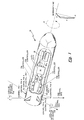
- FIG. 1 is a sketch showing an exemplary airborne vehicle according to the invention to illustrate in the simplest and clearest manner the way in which fin deflection may be reduced; and
- FIG. 2 is a flow chart of a method implemented by the autopilot of FIG. 1 to provide the requisite commands contemplated by the invention.
- Before departing on a detailed explanation of the contemplated invention, it should be appreciated that, although the vehicle is described as a missile having control fins, the vehicle could include any vehicle controlled by control surfaces such as a rocket ship in space having jet exhaust ports as control surfaces, a torpedo in water having either control fins or exhaust ports as control surfaces and a missile having jet exhaust ports.
- Referring now to FIG. 1, it may be seen that a vehicle, such as an airborne vehicle and here
missile 10, is shown to include a plurality of control surfaces, here control fins including control fin 1,control fin 2,control fin 3 and control fin 4. Each of the plurality of control fins is able to provide angular deflection such that the amount of angular deflection provided by each one of the plurality of control fins controls the course of flight of themissile 10. The control fins 1, 2, 3 and 4 are constructed and attached to themissile 10 in a known manner. The amount of angular deflection provided by each of thecontrol fins fin controller 16,fin controller 18,fin controller 20 andfin controller 22. Each of thefin controllers autopilot 14. The control signal fed from theautopilot 14 controls the amount of angular deflection provided bycontrol fins corresponding fin controller autopilot 14 is fed command signals including a pitch command, δ Pc, a yaw command, δ Yc, and a roll command, δ Rc, from aguidance system 12. Thus, as shown, controlfin 2 and control fin 4 provide control in pitch, P, (also referred to as elevation) of themissile 10 and control fin 1 andcontrol fin 3 provide control in yaw, Y, (also referred to as azimuth) of themissile 10. The control fins 1, 2, 3 and 4 also provide control of roll, R, of the missile as described further hereinafter. - As shown in FIG. 1, it should be apparent the
missile 10 includes a boresight line which is coaxial with a centerline of an antenna which is part of theguidance system 12. A target T is located some distance from themissile 10 and using the boresight line as a reference, theguidance system 12 develops a boresight error in pitch and a boresight error in yaw. Using proportional navigation in a known manner, theguidance system 12 provides the pitch command, the yaw command and the roll command to theautopilot 14 to steer themissile 10 along a trajectory to intercept the target T. - It should be appreciated that many factors are entertained by the
guidance system 12 to provide the pitch, yaw and roll commands to theautopilot 14. For example, it is known that, depending on the maneuver, a deflection by thecontrol fins 1 and 3 to provide a control in yaw may induce a roll by themissile 10 due to the aerodynamic environment of themissile 10. Known techniques are used to correct such factors and to have an understanding of the operation of the present invention discussion of such techniques are not necessary. - Defining a Cartesian coordinate system with an X axis, a Y axis and a Z axis, viewing the
missile 10 from the rear, the X axis extends along the center of themissile 10, the Y axis extends along a line provided bycontrol fins 4 and 2 and the Z axis extends along a line provided by control fins 1 and 3. It should be appreciated a pitch plane is defined by the XZ axis and a yaw plane is defined by the XY axis. Angular fin deflection is defined by the right hand rule. Defining angular deflection by the right hand rule, a positive roll command would cause themissile 10 to roll in a clockwise direction. Complexing our definition of terms, if a term 8Fc defines the angular deflection of each fin wherein F is one of the control fins, then 81c defines the angular deflection of control fin 1, 82c defines the angular deflection ofcontrol fin 2, 83c defines the angular deflection ofcontrol fin 3 and 84c defines the angular deflection of control fin 4. With such an arrangement, a pitch fin command 8Pc would equal (δ2c + δ4c)÷2, a yawfin command δ Yc would equal (81 + δ3c)÷2 and aroll fin command 8Rc would equal (δ4c - 82e) + (δ1c- 83e). In such a coordinate system,control fins 4 and 2 provide control of pitch, P, control fins 1 and 3 provide control of yaw, Y, andcontrol fins - In a vehicle, including
missile 10, theguidance system 12 provides the pitch command 8Pc, the yaw command 8Yc and theroll command 8c to theautopilot 14 wherein, using the coordinate system defined hereinbefore, theautopilot 14 provides fin control signals to therespective fin controllers control fins 1 and 3 to provide control of yaw, Y, and control fins 1, 2, 3 and 4 to provide, equally, control of roll R. Thus, for example, if a pitch command of twenty-five degrees, a yaw command of ten degrees and a roll command of ten degrees is fed to theautopilot 14 from theguidance system 12, then theautopilot 14 will provide appropriate control signals to each one of thefin controllers autopilot 14 would provide a control signal to thefin controller 18 to deflect thecontrol fin 2 an amount of twenty-five degrees, and provide a control signal to thefin controller 22 to deflect the control fin 4 an amount of twenty-five degree. To accommodate the yaw fin command of ten degrees, theautopilot 14 would provide a control signal to fincontroller 16 to deflect the control fin 1 an amount of ten degrees and provide a control signal tofin controller 20 to deflect thecontrol fin 3 an amount of ten degrees. To accommodate the roll command of plus ten degrees, theautopilot 14 would modify the control signal to fincontroller 16 to deflect the control fin 1 an amount of 12.5 degrees instead of ten degrees, modify the control signal tofin controller 18 to deflect thecontrol fin 2 an amount of 22.5 degrees instead of 25 degrees, modify the control signal tofin controller 20 to deflectcontrol fin 3 an amount of 7.5 degrees instead of ten degrees and modify the control signal to fincontroller 22 to deflect control fin 4 an amount of 27.5 degrees instead of 25 degrees. Recapitulating, a pitch fin command of twenty-five degrees, a yaw fin command of ten degrees and a roll fin command of ten degrees fed to theautopilot 14 will cause theautopilot 14 to provide appropriate control signals to therespective fin controllers control fin 2 is deflected 22.5 degrees,control fin 3 is deflected 7.5 degrees and control fin 4 is deflected 27.5 degrees. Although satisfactory for some instances, such a configuration can be a problem. For example, if themissile 10 is configured such that control fins 1, 2, 3 and 4 can provide a maximum angular deflection of plus or minus twenty-five degrees, then in the present example, control fin 4 cannot deflect the necessary amount. In such an environment, typically theautopilot 14 gives precedence to the roll command, so that, in the present example, control fin 4 is deflected 25 degrees,control fin 2 is deflected 20 degrees, and control fins 1 and 3 are deflected 12.5 degrees and 7.5 degrees, respectively. With such an arrangement, invoking roll command preference the pitch command is reduced to an equivalent value of 22.5°
- Referring now to FIGS. 1 and 2, a method of operating a vehicle, here
missile 10, is shown to include apportioning the roll command such that control fin deflection is minimized. As described hereinbefore, the pitch command, 8Pc, the yaw command, 8Ye, and theroll command 8Rc is provided to theautopilot 14 from theguidance system 12. A pitch-to-roll command ratio is calculated equal to an absolute value of the pitch command divided by the roll command and a yaw-to-roll command ratio is calculated equal to an absolute value of the yaw command divided by the roll command. The yaw-to-roll command ratio is differenced with the pitch-to-roll command ratio and if the result thereof is equal to or greater than a value 0.5, then all of the roll command is apportioned to theyaw fins 1 and 3,
pitch fins 2 and 4,
pitch fins 2 and 4,
yaw fins 1, and 3,
yaw fins 1 and 3 and thepitch fins 2 and 4 in a manner as to be described. - If the value of the yaw-to-roll command ratio differenced with the pitch-to-yaw command is less than 0.5 and the value of the pitch-to-roll command ratio differenced with the yaw-to-roll value is less than 0.5, then a first portion of the roll command is apportioned to the
pitch fins 2 and 4, the first portion of the roll command

yaw fins 1 and 3. With such an arrangement, if theautopilot 14 of themissile 10 provides fin commands having a roll portion, a yaw portion and a pitch portion, then the required roll command can be apportioned entirely to thepitch fins 2 and 4, if theyaw fins 1 and 3 are commanded to large deflection angles or, alternatively, the required roll command can be apportioned entirely to theyaw fins 1 and 3, if thepitch fins 2 and 4 are commanded to large deflections. If theyaw fins 1 and 3 thepitch fins 2 and 4 are sufficiently close in value (as determined by the pitch-to-roll command ratio and yaw-to-roll command ratio), then the roll command is apportioned between thepitch fins 2 and 4 and theyaw fins 1 and 3 as described hereinabove. - Now, for example, if we have an environment wherein the
autopilot 14 is fed a pitch command of twenty-five degrees, a yaw command of ten degrees and a roll command of ten degrees from theguidance system 12, then theautopilot 14 will provide control signals to thefin controller pitch fins 2 and 4 is zero,
yaw fins 1 and 3,
autopilot 14 would provide a control signal to thefin controller 16 to deflect the control fin 1 an amount of 15 degrees, provide a control signal to thefin controller 18 to deflect thecontrol fin 2 an amount of 25 degrees, provide a control signal to thefin controller 20 to deflect thecontrol fin 3 an amount of five degrees and provide a control signal to thefin controller 22 to deflect the control fin 4 an amount of 25 degrees. - It should now be apparent, by apportioning all of the roll command, 8Rc, to the
yaw fins 1 and 3 and apportioning none of the roll command to thepitch fins 2 and 4, the angular deflection of control fin 4 is reduced below the angular deflection limit of 25 degrees as described in the example. - As a first alternative, if we have an environment wherein the
autopilot 14 is fed a pitch command of ten degrees, a yaw command of twenty-five degrees and a roll command of ten degrees from theguidance system 12, then theautopilot 14 will provide control signals to thefin controllers pitch fins 2 and 4,
yaw fins 1 and 3,
autopilot 14 would provide a control signal to thefin controller 16 to deflect the control fin 1 an amount of 25 degrees, provide a control signal to thefin controller 18 to deflect thecontrol fin 2 an amount of five degrees, provide a control signal to thefin controller 20 to deflect thecontrol fin 3 an amount of 25 degrees and provide a control signal to thefin controller 22 to deflect the control fin 4 an amount of 15 degrees. - It should be apparent, by apportioning all of the roll command, 8Rc, to the
pitch fins 2 and 4 and apportioning none of the roll command to theyaw fins 1 and 3, the angular deflection of the control fin 1 is reduced below the angular deflection limit of 25 degrees. - As a second alternative, if we have an environment wherein the
autopilot 14 is fed a pitch command of twenty degrees, a yaw command of fifteen degrees and a roll command of fifteen degrees from theguidance system 12, then theautopilot 14 will provide control signals to thefin controllers roll command 8Rc is apportioned between thepitch fins 2 and 4 and theyaw fins 1 and 3 in the following manner. - Since the value of the yaw-to-roll command ratio differenced with the pitch-to-yaw command ratio is less than 0.5 and the value of the pitch-to-roll command ratio differenced with the yaw-to-roll command ratio is less than 0.5, then a first portion of the roll command is apportioned to the
pitch fins 2 and 4, the first portion of the roll command being the percentage of the roll command equal to the pitch-to-roll command ratio differenced with the yaw-to-roll command ratio added to 0.5. - For the present example, the first portion of the roll command would equal 1.0 - 1.333 which equals - 0.333 which is added to 0.5 providing the value 0.167. Thus, approximately 16.7 percent of the total roll command is apportioned to the
pitch fins 2 and 4,
- For the present example, the second portion of the roll command would equal 1.0 - 0.167 providing the value 0.833. Thus, approximately 83.3 percent of the total roll command is apportioned to the
yaw fins 1 and 3,
- With the foregoing in mind, in the present example of the
autopilot 14 being fed a pitch command of twenty degrees, a yaw command of fifteen degrees and a roll command of fifteen degrees, theautopilot 14 provides a control signal to thefin controller 16 to deflect the control fin 1 an amount of 21.25 degrees, a control signal to thefin controller 18 to deflect thecontrol fin 2 an amount of 18.75 degrees, a control signal to thefin controller 20 to deflect thecontrol fin 3 an amount of 8.75 degrees and a control signal to thefin controller 22 to deflect the control fin 4 an amount of 21.25 degrees. It should be appreciated that when the roll command is apportioned between thepitch fins 2 and 4 and theyaw fins 1 and 3, then the pitch control fin with the maximum deflection and the yaw control fin with the maximum deflection are deflected an equal amount. With such an arrangement, the maximum fin deflection required of thecontrol fins - Referring now to FIG. 2, the method as described hereinbefore is shown implemented by the
autopilot 14 having adigital computer 50 andadders roll command 8Rc are fed intocomputer 50. The pitch command 8Pc is also fed intoadder 68 andsubtractor 64 and the yaw command 8Yc is also fed intoadder 62 andsubtractor 66. Using the technique as described hereinbefore, the computer calculates the value of the portion of the roll command that is apportioned to thepitch fins 2 and 4 (Fig. 1),
multiplier 52 and calculates the value of the portion of the roll command that is apportioned to the yaw fins 1 and 3 (FIG. 1),
roll command 8Rc is also divided by two and fed to a second input ofmultipliers 52 and 54, respectfully. - The output of the
multiplier 52 is fed to a second input ofadder 68 and added to the pitch command 8Pc to provide the control signal
fin controller 22 to deflect the control fin 4 accordingly. The output of themultiplier 52 is also fed to thesubtractor 64 and subtracted from the pitch command 8Pc to provide the control signal
fin controller 18 to deflect the control fin 4 accordingly. - The output of the multiplier 54 is fed to a second input of
adder 62 and added to the yaw command 8Yc to provide the control signal
fin controller 16 to defect the control fin 1 accordingly. The output of the multiplier 54 is also fed to a second input ofsubtractor 66 and subtracted from the yaw command 8Yc to provide the control signal
fin controller 20 to deflect thecontrol fin 3 accordingly. - Having described this invention, it will now be apparent to one of skill in the art that the disposition of the control fins may be changed without affecting this invention. Further, the coordinate system used to describe the invention could be changed from the one discussed. It is felt, therefore, that this invention should not be restricted to its disclosed embodiment, but rather should be limited only by the spirit and scope of the appended claims.
Claims (11)
Applications Claiming Priority (2)
| Application Number | Priority Date | Filing Date | Title |
|---|---|---|---|
| US672279 | 1976-03-31 | ||
| US07/672,279 US5088658A (en) | 1991-03-20 | 1991-03-20 | Fin command mixing method |
Publications (3)
| Publication Number | Publication Date |
|---|---|
| EP0505071A2 true EP0505071A2 (en) | 1992-09-23 |
| EP0505071A3 EP0505071A3 (en) | 1993-10-20 |
| EP0505071B1 EP0505071B1 (en) | 1997-12-29 |
Family
ID=24697897
Family Applications (1)
| Application Number | Title | Priority Date | Filing Date |
|---|---|---|---|
| EP92302013A Expired - Lifetime EP0505071B1 (en) | 1991-03-20 | 1992-03-10 | A fin command mixing method |
Country Status (6)
| Country | Link |
|---|---|
| US (1) | US5088658A (en) |
| EP (1) | EP0505071B1 (en) |
| JP (1) | JPH05108157A (en) |
| DE (1) | DE69223667T2 (en) |
| ES (1) | ES2110469T3 (en) |
| GR (1) | GR3025938T3 (en) |
Cited By (1)
| Publication number | Priority date | Publication date | Assignee | Title |
|---|---|---|---|---|
| RU2632550C1 (en) * | 2016-10-28 | 2017-10-05 | Публичное акционерное общество "Авиационная холдинговая компания "Сухой" | Aircraft |
Families Citing this family (15)
| Publication number | Priority date | Publication date | Assignee | Title |
|---|---|---|---|---|
| US5593109A (en) * | 1995-01-10 | 1997-01-14 | Lucas Western, Inc. | Actuator system and method |
| US5631830A (en) * | 1995-02-03 | 1997-05-20 | Loral Vought Systems Corporation | Dual-control scheme for improved missle maneuverability |
| US5590850A (en) * | 1995-06-05 | 1997-01-07 | Hughes Missile Systems Company | Blended missile autopilot |
| US6308911B1 (en) | 1998-10-30 | 2001-10-30 | Lockheed Martin Corp. | Method and apparatus for rapidly turning a vehicle in a fluid medium |
| US6637699B2 (en) | 2002-03-25 | 2003-10-28 | Lockheed Martin Corporation | Method and apparatus for controlling a trajectory of a projectile |
| US6921052B2 (en) * | 2003-11-28 | 2005-07-26 | The United States Of America As Represented By The Secretary Of The Army | Dragless flight control system for flying objects |
| IL177527A (en) * | 2006-08-16 | 2014-04-30 | Rafael Advanced Defense Sys | Target-seeking missile |
| FR2909462B1 (en) * | 2006-12-05 | 2008-12-26 | Airbus France Sas | METHOD AND DEVICE FOR ACTIVE CONTROL OF THE TANGULATION OF AN AIRCRAFT. |
| US7781709B1 (en) * | 2008-05-05 | 2010-08-24 | Sandia Corporation | Small caliber guided projectile |
| US8803052B2 (en) * | 2010-04-08 | 2014-08-12 | Bae Systems Information And Electronic Systems Integration Inc. | Predictive roll capture |
| US9037315B2 (en) * | 2013-06-06 | 2015-05-19 | Raytheon Company | Air vehicle control system and method |
| US9222755B2 (en) * | 2014-02-03 | 2015-12-29 | The Aerospace Corporation | Intercepting vehicle and method |
| CN106081140B (en) * | 2016-07-13 | 2019-01-22 | 西藏长源动力科技有限公司 | A kind of big gun penetrates UAV autopilot mounting rack |
| CN106444807B (en) * | 2016-09-29 | 2019-04-12 | 湖北航天技术研究院总体设计所 | A kind of compound attitude control method of grid rudder and Lateral jet |
| US11619473B2 (en) | 2021-01-11 | 2023-04-04 | Bae Systems Information And Electronic Systems Integration Inc. | Command mixing for roll stabilized guidance kit on gyroscopically stabilized projectile |
Citations (2)
| Publication number | Priority date | Publication date | Assignee | Title |
|---|---|---|---|---|
| DE2239398A1 (en) * | 1972-08-10 | 1974-02-21 | Bodenseewerk Geraetetech | CONTROL DEVICE FOR AIRCRAFT |
| US3946968A (en) * | 1974-08-02 | 1976-03-30 | Raytheon Company | Apparatus and method for aerodynamic cross-coupling reduction |
Family Cites Families (4)
| Publication number | Priority date | Publication date | Assignee | Title |
|---|---|---|---|---|
| US2824710A (en) * | 1949-01-05 | 1958-02-25 | Albert C Hall | Control system for guided missiles |
| US2967031A (en) * | 1956-10-29 | 1961-01-03 | Honeywell Regulator Co | Control apparatus for dirigible craft |
| US3575362A (en) * | 1968-10-03 | 1971-04-20 | William M Hammond | Adaptive missile control system incorporating a supervisory loop |
| US4530476A (en) * | 1981-08-12 | 1985-07-23 | E-Systems, Inc. | Ordnance delivery system and method including remotely piloted or programmable aircraft with yaw-to-turn guidance system |
-
1991
- 1991-03-20 US US07/672,279 patent/US5088658A/en not_active Expired - Lifetime
-
1992
- 1992-03-10 DE DE69223667T patent/DE69223667T2/en not_active Expired - Lifetime
- 1992-03-10 ES ES92302013T patent/ES2110469T3/en not_active Expired - Lifetime
- 1992-03-10 EP EP92302013A patent/EP0505071B1/en not_active Expired - Lifetime
- 1992-03-19 JP JP4063045A patent/JPH05108157A/en active Pending
-
1998
- 1998-01-16 GR GR980400108T patent/GR3025938T3/en unknown
Patent Citations (2)
| Publication number | Priority date | Publication date | Assignee | Title |
|---|---|---|---|---|
| DE2239398A1 (en) * | 1972-08-10 | 1974-02-21 | Bodenseewerk Geraetetech | CONTROL DEVICE FOR AIRCRAFT |
| US3946968A (en) * | 1974-08-02 | 1976-03-30 | Raytheon Company | Apparatus and method for aerodynamic cross-coupling reduction |
Cited By (1)
| Publication number | Priority date | Publication date | Assignee | Title |
|---|---|---|---|---|
| RU2632550C1 (en) * | 2016-10-28 | 2017-10-05 | Публичное акционерное общество "Авиационная холдинговая компания "Сухой" | Aircraft |
Also Published As
| Publication number | Publication date |
|---|---|
| US5088658A (en) | 1992-02-18 |
| JPH05108157A (en) | 1993-04-30 |
| DE69223667T2 (en) | 1998-08-27 |
| DE69223667D1 (en) | 1998-02-05 |
| EP0505071B1 (en) | 1997-12-29 |
| EP0505071A3 (en) | 1993-10-20 |
| GR3025938T3 (en) | 1998-04-30 |
| ES2110469T3 (en) | 1998-02-16 |
Similar Documents
| Publication | Publication Date | Title |
|---|---|---|
| EP0505071A2 (en) | A fin command mixing method | |
| US7988097B2 (en) | Precision attitude control system for gimbaled thruster | |
| Shima et al. | Time-varying linear pursuit-evasion game models with bounded controls | |
| EP1244946B1 (en) | Spatial avoidance method and apparatus | |
| EP2483628B1 (en) | System and method for divert and attitude control in flight vehicles | |
| EP2188144B1 (en) | Stall, buffeting, low speed and high attitude protection systems | |
| US6244536B1 (en) | Air to air homing missile guidance | |
| US7446291B1 (en) | Augmented proportional navigation guidance law using angular acceleration measurements | |
| US3946968A (en) | Apparatus and method for aerodynamic cross-coupling reduction | |
| Imado et al. | Missile guidance algorithm against high-g barrel roll maneuvers | |
| US5094406A (en) | Missile control system using virtual autopilot | |
| US5951607A (en) | Autonomous craft controller system for landing craft air cushioned vehicle | |
| US5448486A (en) | Orthogonal polar coordinate system to accommodate polar navigation | |
| EP0222571A2 (en) | Line of sight missile guidance | |
| US4236687A (en) | Ejection seat with pitch, roll and yaw control | |
| EP2862806A1 (en) | Differential throttling control enhancement | |
| US4142695A (en) | Vehicle guidance system | |
| US5984237A (en) | Delta-V targeting system for three-axis controlled spacecraft | |
| US5722614A (en) | Missile guidance command limitation system for dynamic controllability criteria | |
| CN109799826B (en) | Thrust distribution method of ship propeller system | |
| US20100070105A1 (en) | Optimal Guidance Blender for a Hovering/Flying Vehicle | |
| RU2392186C2 (en) | Method to control twin-engine aircraft and system to this end | |
| US4044237A (en) | Missile maneuver concept | |
| CN114440707B (en) | Aircraft guidance method, device and system for top and side collaborative interception | |
| US6651004B1 (en) | Guidance system |
Legal Events
| Date | Code | Title | Description |
|---|---|---|---|
| PUAI | Public reference made under article 153(3) epc to a published international application that has entered the european phase |
Free format text: ORIGINAL CODE: 0009012 |
|
| AK | Designated contracting states |
Kind code of ref document: A2 Designated state(s): BE DE ES FR GB GR IT |
|
| PUAL | Search report despatched |
Free format text: ORIGINAL CODE: 0009013 |
|
| AK | Designated contracting states |
Kind code of ref document: A3 Designated state(s): BE DE ES FR GB GR IT |
|
| 17P | Request for examination filed |
Effective date: 19940406 |
|
| 17Q | First examination report despatched |
Effective date: 19960228 |
|
| GRAG | Despatch of communication of intention to grant |
Free format text: ORIGINAL CODE: EPIDOS AGRA |
|
| GRAG | Despatch of communication of intention to grant |
Free format text: ORIGINAL CODE: EPIDOS AGRA |
|
| GRAG | Despatch of communication of intention to grant |
Free format text: ORIGINAL CODE: EPIDOS AGRA |
|
| GRAH | Despatch of communication of intention to grant a patent |
Free format text: ORIGINAL CODE: EPIDOS IGRA |
|
| GRAH | Despatch of communication of intention to grant a patent |
Free format text: ORIGINAL CODE: EPIDOS IGRA |
|
| GRAA | (expected) grant |
Free format text: ORIGINAL CODE: 0009210 |
|
| ITF | It: translation for a ep patent filed |
Owner name: BARZANO' E ZANARDO MILANO S.P.A. |
|
| AK | Designated contracting states |
Kind code of ref document: B1 Designated state(s): BE DE ES FR GB GR IT |
|
| REF | Corresponds to: |
Ref document number: 69223667 Country of ref document: DE Date of ref document: 19980205 |
|
| REG | Reference to a national code |
Ref country code: ES Ref legal event code: FG2A Ref document number: 2110469 Country of ref document: ES Kind code of ref document: T3 |
|
| ET | Fr: translation filed | ||
| PLBE | No opposition filed within time limit |
Free format text: ORIGINAL CODE: 0009261 |
|
| STAA | Information on the status of an ep patent application or granted ep patent |
Free format text: STATUS: NO OPPOSITION FILED WITHIN TIME LIMIT |
|
| 26N | No opposition filed | ||
| REG | Reference to a national code |
Ref country code: GB Ref legal event code: IF02 |
|
| PGFP | Annual fee paid to national office [announced via postgrant information from national office to epo] |
Ref country code: IT Payment date: 20110321 Year of fee payment: 20 Ref country code: FR Payment date: 20110317 Year of fee payment: 20 |
|
| PGFP | Annual fee paid to national office [announced via postgrant information from national office to epo] |
Ref country code: GR Payment date: 20110217 Year of fee payment: 20 |
|
| PGFP | Annual fee paid to national office [announced via postgrant information from national office to epo] |
Ref country code: GB Payment date: 20110309 Year of fee payment: 20 Ref country code: BE Payment date: 20110311 Year of fee payment: 20 Ref country code: ES Payment date: 20110414 Year of fee payment: 20 Ref country code: DE Payment date: 20110302 Year of fee payment: 20 |
|
| REG | Reference to a national code |
Ref country code: DE Ref legal event code: R071 Ref document number: 69223667 Country of ref document: DE |
|
| REG | Reference to a national code |
Ref country code: DE Ref legal event code: R071 Ref document number: 69223667 Country of ref document: DE |
|
| BE20 | Be: patent expired |
Owner name: *RAYTHEON CY Effective date: 20120310 |
|
| REG | Reference to a national code |
Ref country code: GB Ref legal event code: PE20 Expiry date: 20120309 |
|
| PG25 | Lapsed in a contracting state [announced via postgrant information from national office to epo] |
Ref country code: DE Free format text: LAPSE BECAUSE OF EXPIRATION OF PROTECTION Effective date: 20120311 |
|
| REG | Reference to a national code |
Ref country code: GR Ref legal event code: MA Ref document number: 980400108 Country of ref document: GR Effective date: 20120311 |
|
| REG | Reference to a national code |
Ref country code: ES Ref legal event code: FD2A Effective date: 20120604 |
|
| PG25 | Lapsed in a contracting state [announced via postgrant information from national office to epo] |
Ref country code: GB Free format text: LAPSE BECAUSE OF EXPIRATION OF PROTECTION Effective date: 20120309 |
|
| PG25 | Lapsed in a contracting state [announced via postgrant information from national office to epo] |
Ref country code: ES Free format text: LAPSE BECAUSE OF EXPIRATION OF PROTECTION Effective date: 20120311 |