EP0504880A2 - Mail center management system - Google Patents
Mail center management system Download PDFInfo
- Publication number
- EP0504880A2 EP0504880A2 EP92104787A EP92104787A EP0504880A2 EP 0504880 A2 EP0504880 A2 EP 0504880A2 EP 92104787 A EP92104787 A EP 92104787A EP 92104787 A EP92104787 A EP 92104787A EP 0504880 A2 EP0504880 A2 EP 0504880A2
- Authority
- EP
- European Patent Office
- Prior art keywords
- devices
- subscriber
- subscriber terminals
- network
- Prior art date
- Legal status (The legal status is an assumption and is not a legal conclusion. Google has not performed a legal analysis and makes no representation as to the accuracy of the status listed.)
- Granted
Links
Images


Classifications
-
- H—ELECTRICITY
- H04—ELECTRIC COMMUNICATION TECHNIQUE
- H04M—TELEPHONIC COMMUNICATION
- H04M3/00—Automatic or semi-automatic exchanges
- H04M3/42—Systems providing special services or facilities to subscribers
- H04M3/50—Centralised arrangements for answering calls; Centralised arrangements for recording messages for absent or busy subscribers ; Centralised arrangements for recording messages
- H04M3/53—Centralised arrangements for recording incoming messages, i.e. mailbox systems
- H04M3/533—Voice mail systems
- H04M3/53325—Interconnection arrangements between voice mail systems
-
- H—ELECTRICITY
- H04—ELECTRIC COMMUNICATION TECHNIQUE
- H04L—TRANSMISSION OF DIGITAL INFORMATION, e.g. TELEGRAPHIC COMMUNICATION
- H04L51/00—User-to-user messaging in packet-switching networks, transmitted according to store-and-forward or real-time protocols, e.g. e-mail
-
- H—ELECTRICITY
- H04—ELECTRIC COMMUNICATION TECHNIQUE
- H04L—TRANSMISSION OF DIGITAL INFORMATION, e.g. TELEGRAPHIC COMMUNICATION
- H04L51/00—User-to-user messaging in packet-switching networks, transmitted according to store-and-forward or real-time protocols, e.g. e-mail
- H04L51/21—Monitoring or handling of messages
- H04L51/23—Reliability checks, e.g. acknowledgments or fault reporting
-
- H—ELECTRICITY
- H04—ELECTRIC COMMUNICATION TECHNIQUE
- H04M—TELEPHONIC COMMUNICATION
- H04M3/00—Automatic or semi-automatic exchanges
- H04M3/08—Indicating faults in circuits or apparatus
- H04M3/12—Marking faulty circuits "busy"; Enabling equipment to disengage itself from faulty circuits ; Using redundant circuits; Response of a circuit, apparatus or system to an error
-
- H—ELECTRICITY
- H04—ELECTRIC COMMUNICATION TECHNIQUE
- H04M—TELEPHONIC COMMUNICATION
- H04M3/00—Automatic or semi-automatic exchanges
- H04M3/42—Systems providing special services or facilities to subscribers
- H04M3/50—Centralised arrangements for answering calls; Centralised arrangements for recording messages for absent or busy subscribers ; Centralised arrangements for recording messages
- H04M3/53—Centralised arrangements for recording incoming messages, i.e. mailbox systems
- H04M3/5307—Centralised arrangements for recording incoming messages, i.e. mailbox systems for recording messages comprising any combination of audio and non-audio components
Definitions
- the present invention generally relates to a mail center management system.
- a new network has been proposed in which a mail center, which provides various mail services by means of various media, such as speech, facsimile and images, is provided in the network.
- a main center is provided in a local area network.
- the mail center is designed, taking into account a future increasing demand of mail services. Hence, it is desired that the main center can be easily expanded without greatly changing the system configuration.
- a more specific object of the present invention is to provide a mail center management system in which the system can be easily expanded without stopping the system and causing inconvenience to users.
- the mail center management system includes a first network accommodating a plurality of subscriber terminals via lines, and a plurality of mail devices connected to the first network.
- Each of the mail devices which has a device number and subscriber information about all the subscriber terminals, includes a storage medium for storing mails received from the subscriber terminals.
- a second network connects the mail devices to each other and transfers the mails between the mail devices.
- Each of the mail devices includes a first pact for determining whether a request to transfer from a first one of the subscriber terminals to a second one of the subscriber terminals includes a subscriber number of the second one of the subscriber terminals or the device number of one of the mail devices together with the subscriber number. Further, each of the mail devices includes a second part for storing, via the second network, the mail in the storage medium of one of the mail devices to which the first and second ones of the subscriber terminals are connected when the first means determines that the request includes no device number and for storing, via the first and second networks, the mail in the storage medium of one of the mail devices to which the second one of the mail devices is connected when the first means determines that the request includes the device number together with the subscriber number.
- Fig.1 shows an outline of the main center management system of the present invention.
- the system shown In Fig.1 comprises subscriber terminals 1-1 - 1-4, a network 2, such as a private branch exchange or a local area network, mail devices 3-1 and 3-2 installed in a mail center, and a communication network 4 connecting the mail devices 3-1 and 3-2.
- a network 2 such as a private branch exchange or a local area network
- mail devices 3-1 and 3-2 installed in a mail center
- a communication network 4 connecting the mail devices 3-1 and 3-2.
- a plurality of mail devices each having a predetermined capability, are provided, as shown in Fig.1.
- Some additional mail devices can be connected to the system.
- Identification numbers necessary to respectively specify the mail devices have hierarchical numbering system.
- the subscriber terminals 1-1 - 1-4 may be grouped on the basis of which main center each of the subscriber terminals is connected to. In the case shown in Fig1. the subscriber terminals 1-1 and 1-2 belong to the group having the mail device 3-1, and the subscriber terminals 1-3 and 1-4 belong to the group having the mail device 3-2.
- Each of the main centers 3-1 and 3-2 has registered information about subscriber terminals connected to the other group. If a failure has occurred in one of the mail devices 3-1 and 3-2, which has not worked, the subscriber terminals which belong to the group relating to the defective mail device can continuously receive the mail services via the mail device other than the defective mail device.
- each hierarchical number includes a mail device number and a subscriber number.
- device numbers "10” and “20” are assigned to the mail devices 3-1 and 3-2, respectively.
- Subscriber numbers "01" - “04” are assigned to the subscriber terminals 1-1 - 1-4, respectively.
- the subscribers 1-1 and 1-2 belong to the group having device number "10" (3-1)
- the subscribers 1-3 and 104 belong to the group having device number "20" (3-2).
- Each of the mail devices 3-1 and 3-2 stores the registered subscriber numbers 01" - "04" of all the subscriber devices in the system.
- each of the mail devices 3-1 and 3-2 includes information showing that a mail box is provided in its own storage device. The above information is added to each subscriber number.
- the mail boxes of the subscribers 1-1 and 1-2 are formed in the mail device 3-1, and the mail boxes of the subscribers 1-3 and 1-4 are formed in the mail device 3-2.
- a request to deliver a mail from a subscriber terminal in one group to a subscriber terminal in the other group comprises information composed of the subscriber number of the destination terminal and the device number having the corresponding mail box. If the terminal device 1-1 has a request to send a mail to the terminal device 1-3, the request comprises information "2003". If a mall is requested to send from a subscriber terminal to a subscriber terminal in the same group, only the subscriber number is sent. For example, if the terminal device 1-1 has a request to send a mail to the terminal device 1-2, the request comprises information "02". Each of the mail devices 3-1 and 3-2 directly delivers the mail to the destination terminal connected thereto, if only the subscriber number is specified. If not only the subscriber number but also the device number are specified, the mail is transferred via the communication network 4.
- a log-on condition (showing whether to receive services using the mail devices) is managed in each of the mail devices 3-1 and 3-2.
- Each of the mail devices 3-1 and 3-2 checks the subscriber number or the combination of the subscriber number and the device number.
- a device number (“30", for example) is assigned to the additional mail device.
- Line circuits for connecting the additional main device to the networks 2 and 4 are provided. All the subscriber numbers in the system are registered in the additional mail device. Further, some mail boxes are formed in the additional mail device. During the procedure for connecting the additional mail device to the system, the existing mail devices 3-1 and 3-2 are continuously working.
- the subscriber terminals belonging to the same group as the defective mail device can access the other mail devices and receive mail services.
- Mails addressed to the subscriber terminals belonging to the same group as the defective mail device can be delivered via the normal mail devices by the normal procedure for specifying the destination terminal.
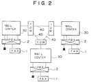
- Fig.2 is a block diagram of a first system structure in which three mail centers 30 are coupled to each other via dedicated high-bit rate digital lines 40.
- the three mail centers 30 are connected to respective PBXs 2 (which correspond to the network 2 shown in Fig.1) via lines.
- Each of the PBXs 2 accommodate a plurality of subscriber terminals, such as telephone sets and facsimile machines (FAX) 1.
- the three mail centers 30 are connectad to respective time-division multiplexing (TDM) devices.
- TDM devices are connected to each other via the high-speed digital dedicated lines 40. Mail information and control data are transferred via the digital lines 40.
- Fig.3 is a block diagram of a second system structure in which the digital lines 40 and the TDM devices are replaced by a packet switching network 41.
- the other structural parts of the system shown in Fig.3 are the same as those shown in Fig2.
- Fig.4 shows an example of each mail center used in the present invention.
- the mail centers shown in Fig.4 are large-scale FAX mail centers used in a LAN. It will now be assumed that initially, only a FAX mail center 3A which is capable of accommodating 1000 subscriber terminals and which has a mail storage device having a capacity of 1GB (giga bytes) is provided and 36 lines connected to the network 2 are connected. If there is a demand to accommodate an increased number of subscribers (less than or equal to 1000), an additional mail storage capacity and an increased number of subscribers are needed to accommodate the increased number of subscribers.
- an additional FAX mail device 3B capable of 1000 subscriber terminals is prepared and assigned device number "11". Information about the 1000 subscriber terminals registered in the FAX mail device 3A is also registered in the FAX mail device 3B. Further, a mail storage device having a storage capacity of 1GB is connected to the FAX mail device 3B. The total mail storage capacity of the system becomes equal to 2GB.
- the FAX mail devices 3A and 3B are connected to each other via a 10Mbps-LAN, which conforms to, for example, the 8802/3-CSMD of the 560.
- Each of the mall devices 3A and 3B may be connected to another main center via a dedicated line or a packet network (see Figs.2 and 3).
- the number of lines increases to twice (72 lines) the initial number of lines (equal to 36) by providing 36 lines connected to the FAX mail device 3B.
- the subscribers are grouped as follows: Subscriber numbers 0001-0499: mail boxes thereof are formed in the mail device 3A and registered as a device 10 group.
- Subscriber numbers 0500-0999 mail boxes thereof are formed in the mail device 3B and registered as a device 11 group.
- the calling subscriber terminal When a subscriber terminal calls another subscriber terminal in the same group In the expanded system shown in Fig.4, the calling subscriber terminal sends the called subscriber number without the group number to the network.
- the calling subscriber terminal When a subscriber terminal calls another subscriber terminal in a different group, the calling subscriber terminal and the number of the different group via a transmitter and a coaxial cable.
- the transmission lines are lines which carry calls from the mail devices
- the reception lines are lines which carry calls terminating at the mail devices.
- the original system is expanded by adding the main device 3B (36 lines), as shown in Fig.4, if 18 lines out of the 36 lines connected to the mail device 3A are used as reception lines, and the remaining lines (54 lines) are used as transmission lines, it is possible for the subscribers in the group of the mail device 3A to access the mail device 3B.
- the address of the destination terminal is specified by adding the group number to the destination subscriber number.
- Fig.5 is a block diagram of a hardware structure of each of the mail devices 3A and 3B.
- the mail device comprises a CPU1 50 for processing programs, a main memory (MM) 51, a CPU2 53 for use in input/output processing, and a matching unit 52 which operatively connects the CPU1 and CPU2 to each other.
- the CPU2 controls the following structural elements.
- a disk controller 54 controls disks in which mail boxes are formed and FAX data are stored.
- a console controller 55 controls a console for use in supervisory and management procedures.
- a LAN communication unit 56 communicates with another mail device via a LAN.
- a center-to-center communication unit 57 communicates with another center via a dedicated line or a packet switching network.
- a plurality of TEL/FAX communication units 58 communicate with PBXs via lines.
- An OMR recognition unit 59 recognizes various OMR sheets.
- An information generator 60 generates a variety of information which is to be transmitted to other devices.
- Fig.6 shows a program architecture used in the mail device. Each program shown in Fig.6 is controlled by an operating system (OS) 61.
- a disk input/output management program 62 which handles system management/main information, controls an inner mail delivery management program 63 for controlling mail delivery in the mail device, and a repeated mail delivery management program 64 for controlling mail delivery via another mail center.
- a center-to-center mail repeating program 67 controls a procedure for transferring a mail to another mall center.
- a FAX/speech input/output program 68 controls inputting and outputting speech and data to FAXs and telephone sets.
- a log-on check program 66 checks a subscriber number and a password number which are input via each subscriber terminal.
- a mail destination check program 65 checks which mail device and which subscriber a requested mail should be transferred.
- a disk control program 69, a console control program 70, a LAM communication program 71, a dedicated line/packet network communication program 72, a FAX/speech communication program 73 and an OMR sheet recognition information generation program 74 are programs which control the disk controller 54, the control controller 55, the LAN communication unit 56, the center-to-center communication unit 57, the TEL/FAX communication units 58, the OMR sheet recognition unit 59 and the information generator 60, respectively.
- Numerals sandwiched between [] in Fig.6 shows a process sequence which is executed after a connection with the subscriber terminal (FAX or telephone set) is established.
- Capital letters A, B and C shown in Fig.6 denote processes which are executed upon request.
- Fig.7 shows various decision tables.
- Fig.7-A shows a log-on decision table, which is referred to when each subscriber is allowed to receive the mail delivery services of the mail devices.
- the subscriber number and password which are input from the subscriber is compared with the contents of the log-on decision table shown in Fig.7-A.
- the mail services are presented to this subscriber.
- Fig.7- shows a decision table used for determining which one of its own device, another center and another mail device direction the requested the mail should be cent to by referring to the input destination address.
- the destination address is specified by the telephone number, it is compared with support telephone numbers registered in the decision table shown in Fig.7.
- Fig.7-C shows an in-device subscriber management table, which is used for determining the terminal informed of the results of the requested communication when the destination is specified by the subscriber telephone number and the real telephone number of the destination terminal to which the mail is delivered. Further, data about the storage capacity of the mail box assigned to each subscriber is defined in the table shown in Fig.7-C.
- Fig.8 is a flowchart of the operation of the above system when the mail delivery service is requested by a PB (Push Button) signal.
- the subscriber number (ID), the password and a function code are sequentially checked at steps 2, 3 and 4, respectively.
- the destination terminal is identified.
- information (data about the delivery request, FAX data and so on) from the calling subscriber is received.
- the established line is disconnected at step 6.
- the received information is sent to the delivery management programs 63 and 64 shown in Fig.6 on the basis of the identified destination.
- the calling subscriber terminal is informed of acknowledgement of the mail delivery request.
- Fig.9 is a flowchart of the operation of the aforementioned system when the mail delivery service is requested by means of the OMR sheet.
- the calling subscriber marks a predetermined area on the OMR sheet in order to input facsimile information indicative of the destination terminal.
- a line is established at step 1 shown in Fig.9, and thereafter the input facsimile information is received at step 2.
- the line is disconnected at step 3.
- the OMR sheet is recognized from the received facsimile information at step 4, and steps 5-8 are successively executed in the same manner as the steps 2-5 shown in Fig.8.
- steps 9 and 10 are executed in the same manner as the steps 8 and 9 shown in Fig.8.
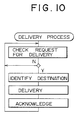
- Fig.9 shows a basic mail delivery process of the mail device. It is determined, at step 1, whether or not there is a request to deliver a mail. When the result of this determination is affirmative, the destination subscriber is identified at step 2, and the mail is delivered thereto at step 3. The calling subscriber is informed of the result of delivery at step 4.
- the present invention it becomes possible to execute the system expansion procedure by using the working facilities without stopping the operation of the system. Further, when a fault has occurred in a mail device, another mail device can immediately provide the mail services to the subscriber terminals connected to the defective mail device. Furthermore, an increase in the number of lines and the storage capacity can be easily obtained. In conventional technology, such an increase cannot be realized by a single mail device. Moreover, it is possible to arbitrarily change the ratio of transmission lines to reception lines. This structure will be very effective in a case where it is requested to simultaneously send facsimile information to a large number of subscriber terminals during a short period. The ratio of transmission lines to reception lines is limited to a range between 1:1 and 1:35 when a single mail device is used. According to the aforementioned embodiment of the present invention, it is possible to obtain such a ratio between 1:1 and 36xN where N is the number of mail devices specifically used for transmission.
- each subscriber is equally assigned a storage capacity of 1/1000.
- each subscriber can be assigned a storage capacity of N/1000 where N is the number of mail devices, and hence a large amount of information can be stored.
- a storage capacity in each of the mail devices equally assigned for each subscriber terminal is denoted by C, each subscriber has a storage capacity of CxN.
Abstract

Description
- The present invention generally relates to a mail center management system.
- Recently, a new network has been proposed in which a mail center, which provides various mail services by means of various media, such as speech, facsimile and images, is provided in the network. For example, such a main center is provided in a local area network. Generally, the mail center is designed, taking into account a future increasing demand of mail services. Hence, it is desired that the main center can be easily expanded without greatly changing the system configuration.
- In the past, two communication devices, such as facsimile machines, transferred information between them. However, recently, there has been a demand to send identical information to a plurality of destination devices. For example, it is required to simultaneously send identical information to a plurality of persons and customers via a network. For this requirement, a mail center as described above is connected to the network. Generally, a single main center is connected to the network. As the number of users increases and/or the number of mails increases, line circuits connected to the network are increased. In addition to an increase in the number of line circuits, or instead thereof, a storage device, such as a disk device, is added to working storage devices. In some cases, some working storage devices may be replaced with new ones.
- If some working storage devices are replaced with new ones, information stored therein must be transferred to the new storage devices. During this data transfer process (a few days to a few weeks), the mail services are not available, Further, there is a possibility that some information may be lost or damaged during the data transfer process.
- It is an object of the present invention to provide a mail center management system in which the above disadvantages are eliminated.
- A more specific object of the present invention is to provide a mail center management system in which the system can be easily expanded without stopping the system and causing inconvenience to users.
- The above objects of the present invention are achieved by a mail center management system having the following structure. That is, the mail center management system includes a first network accommodating a plurality of subscriber terminals via lines, and a plurality of mail devices connected to the first network. Each of the mail devices, which has a device number and subscriber information about all the subscriber terminals, includes a storage medium for storing mails received from the subscriber terminals. A second network connects the mail devices to each other and transfers the mails between the mail devices. Each of the mail devices includes a first pact for determining whether a request to transfer from a first one of the subscriber terminals to a second one of the subscriber terminals includes a subscriber number of the second one of the subscriber terminals or the device number of one of the mail devices together with the subscriber number. Further, each of the mail devices includes a second part for storing, via the second network, the mail in the storage medium of one of the mail devices to which the first and second ones of the subscriber terminals are connected when the first means determines that the request includes no device number and for storing, via the first and second networks, the mail in the storage medium of one of the mail devices to which the second one of the mail devices is connected when the first means determines that the request includes the device number together with the subscriber number.
- Other objects, features and advantages of the present invention will become more apparent from the following detailed description when read in conjunction with the accompanying drawings, in which:
- Fig.1 is a diagram showing an outline of the present invention;
- Fig.2 is a block diagram of a first system structure in which dedicated lines are provided between mail centers;
- Fig.3 is a block diagram of a second system structure in which a packet network is provided between mail centers;
- Fig.4 is a block diagram of the structure of each mail center;
- Fig.5 is a block diagram of a hardware structure of each mail device;
- Fig.6 is a diagram showing programs installed in each mail device;
- Fig.7 is a diagram of decision tables used in each mail device;
- Fig.8 is a flowchart of a basic process executed in each mail device when PB signal is used;
- Fig.9 is a flowchart of a basic process executed in each mail device when an OMR sheet is used;
- Fig.10 is a flowchart of another basic process executed in each mail device.
-
- Fig.1 shows an outline of the main center management system of the present invention. The system shown In Fig.1 comprises subscriber terminals 1-1 - 1-4, a
network 2, such as a private branch exchange or a local area network, mail devices 3-1 and 3-2 installed in a mail center, and acommunication network 4 connecting the mail devices 3-1 and 3-2. - According to the present invention, a plurality of mail devices, each having a predetermined capability, are provided, as shown in Fig.1. Some additional mail devices can be connected to the system. Identification numbers necessary to respectively specify the mail devices have hierarchical numbering system. The subscriber terminals 1-1 - 1-4 may be grouped on the basis of which main center each of the subscriber terminals is connected to. In the case shown in Fig1. the subscriber terminals 1-1 and 1-2 belong to the group having the mail device 3-1, and the subscriber terminals 1-3 and 1-4 belong to the group having the mail device 3-2. Each of the main centers 3-1 and 3-2 has registered information about subscriber terminals connected to the other group. If a failure has occurred in one of the mail devices 3-1 and 3-2, which has not worked, the subscriber terminals which belong to the group relating to the defective mail device can continuously receive the mail services via the mail device other than the defective mail device.
- As has bean described previously, the present invention employs the hierarchical numbering system. More specifically, each hierarchical number includes a mail device number and a subscriber number. In the case shown in Fig.1, device numbers "10" and "20" are assigned to the mail devices 3-1 and 3-2, respectively. Subscriber numbers "01" - "04" are assigned to the subscriber terminals 1-1 - 1-4, respectively. As has been described previously, the subscribers 1-1 and 1-2 belong to the group having device number "10" (3-1), and the subscribers 1-3 and 104 belong to the group having device number "20" (3-2).
- Each of the mail devices 3-1 and 3-2 stores the registered subscriber numbers 01" - "04" of all the subscriber devices in the system. As shown in Fig.1, each of the mail devices 3-1 and 3-2 includes information showing that a mail box is provided in its own storage device. The above information is added to each subscriber number. In the example shown in Fig.1, the mail boxes of the subscribers 1-1 and 1-2 are formed in the mail device 3-1, and the mail boxes of the subscribers 1-3 and 1-4 are formed in the mail device 3-2.
- A request to deliver a mail from a subscriber terminal in one group to a subscriber terminal in the other group comprises information composed of the subscriber number of the destination terminal and the device number having the corresponding mail box. If the terminal device 1-1 has a request to send a mail to the terminal device 1-3, the request comprises information "2003". If a mall is requested to send from a subscriber terminal to a subscriber terminal in the same group, only the subscriber number is sent. For example, if the terminal device 1-1 has a request to send a mail to the terminal device 1-2, the request comprises information "02". Each of the mail devices 3-1 and 3-2 directly delivers the mail to the destination terminal connected thereto, if only the subscriber number is specified. If not only the subscriber number but also the device number are specified, the mail is transferred via the
communication network 4. - A log-on condition (showing whether to receive services using the mail devices) is managed in each of the mail devices 3-1 and 3-2. Each of the mail devices 3-1 and 3-2 checks the subscriber number or the combination of the subscriber number and the device number.
- If an additional mail device is added to the system shown in Fig.1, a device number ("30", for example) is assigned to the additional mail device. Line circuits for connecting the additional main device to the
networks - If one of the mail devices has stopped to operate due to a fault, the subscriber terminals belonging to the same group as the defective mail device can access the other mail devices and receive mail services. Mails addressed to the subscriber terminals belonging to the same group as the defective mail device can be delivered via the normal mail devices by the normal procedure for specifying the destination terminal. Further, by employing the hierarchical numbering system and executing the log-on process with respect to a specific one of the mail devices by using only the subscriber number, it becomes possible to separately use lines specifically used for transferring calls which should be terminated at the mail devices and lines specifically used for transferring messages from the main devices to the subscriber terminals. Furthermore, it becomes possible to arbitrarily determine the ratio of both the differently used lines.
- Fig.2 is a block diagram of a first system structure in which three
mail centers 30 are coupled to each other via dedicated high-bit ratedigital lines 40. The threemail centers 30 are connected to respective PBXs 2 (which correspond to thenetwork 2 shown in Fig.1) via lines. Each of thePBXs 2 accommodate a plurality of subscriber terminals, such as telephone sets and facsimile machines (FAX) 1. The threemail centers 30 are connectad to respective time-division multiplexing (TDM) devices. The TDM devices are connected to each other via the high-speed digitaldedicated lines 40. Mail information and control data are transferred via thedigital lines 40. - Fig.3 is a block diagram of a second system structure in which the
digital lines 40 and the TDM devices are replaced by apacket switching network 41. The other structural parts of the system shown in Fig.3 are the same as those shown in Fig2. - Fig.4 shows an example of each mail center used in the present invention. The mail centers shown in Fig.4 are large-scale FAX mail centers used in a LAN. It will now be assumed that initially, only a FAX mail center 3A which is capable of accommodating 1000 subscriber terminals and which has a mail storage device having a capacity of 1GB (giga bytes) is provided and 36 lines connected to the
network 2 are connected. If there is a demand to accommodate an increased number of subscribers (less than or equal to 1000), an additional mail storage capacity and an increased number of subscribers are needed to accommodate the increased number of subscribers. - In this case, an additional
FAX mail device 3B capable of 1000 subscriber terminals is prepared and assigned device number "11". Information about the 1000 subscriber terminals registered in the FAX mail device 3A is also registered in theFAX mail device 3B. Further, a mail storage device having a storage capacity of 1GB is connected to theFAX mail device 3B. The total mail storage capacity of the system becomes equal to 2GB. TheFAX mail devices 3A and 3B are connected to each other via a 10Mbps-LAN, which conforms to, for example, the 8802/3-CSMD of the 560. Each of themall devices 3A and 3B may be connected to another main center via a dedicated line or a packet network (see Figs.2 and 3). - The number of lines increases to twice (72 lines) the initial number of lines (equal to 36) by providing 36 lines connected to the
FAX mail device 3B. The subscribers are grouped as follows:
Subscriber numbers 0001-0499: mail boxes thereof are formed in the mail device 3A and registered as adevice 10 group. - Subscriber numbers 0500-0999: mail boxes thereof are formed in the
mail device 3B and registered as adevice 11 group. - When a subscriber terminal calls another subscriber terminal in the same group In the expanded system shown in Fig.4, the calling subscriber terminal sends the called subscriber number without the group number to the network. When a subscriber terminal calls another subscriber terminal in a different group, the calling subscriber terminal and the number of the different group via a transmitter and a coaxial cable.
- When a fault has occurred, only the subscriber number is sent without the group number. If both a list in which the group numbers are assigned to the mail devices and a list in which the group numbers are not assigned to the mail devices are registered in the state where a fault has occurred, the latter list is used. It is possible to designate the destination subscriber terminal by marking a specific position on a mark sheet and optically reading the mark by means of an optical mark reader. In this case, a different type of mark sheet in which no group numbers are assigned is used. A11 the subscriber terminals are informed of these changes, and changed so that the changes become effective.
- It will now be assumed that the ratio of transmission lines to reception lines is equal to 18 : 18 in the configuration shown in Fig.4. The transmission lines are lines which carry calls from the mail devices, and the reception lines are lines which carry calls terminating at the mail devices.
- When the original system is expanded by adding the
main device 3B (36 lines), as shown in Fig.4, if 18 lines out of the 36 lines connected to the mail device 3A are used as reception lines, and the remaining lines (54 lines) are used as transmission lines, it is possible for the subscribers in the group of the mail device 3A to access themail device 3B. In this case, the address of the destination terminal is specified by adding the group number to the destination subscriber number. In this case, the ratio of the transmission lines to the reception lines = 18 : 54 = 1 : 3. - Fig.5 is a block diagram of a hardware structure of each of the
mail devices 3A and 3B. The mail device comprises a CPU1 50 for processing programs, a main memory (MM) 51, a CPU2 53 for use in input/output processing, and amatching unit 52 which operatively connects the CPU1 and CPU2 to each other. The CPU2 controls the following structural elements. Adisk controller 54 controls disks in which mail boxes are formed and FAX data are stored. Aconsole controller 55 controls a console for use in supervisory and management procedures. ALAN communication unit 56 communicates with another mail device via a LAN. A center-to-center communication unit 57 communicates with another center via a dedicated line or a packet switching network. A plurality of TEL/FAX communication units 58 communicate with PBXs via lines. AnOMR recognition unit 59 recognizes various OMR sheets. Aninformation generator 60 generates a variety of information which is to be transmitted to other devices. - Fig.6 shows a program architecture used in the mail device. Each program shown in Fig.6 is controlled by an operating system (OS) 61. A disk input/
output management program 62, which handles system management/main information, controls an inner maildelivery management program 63 for controlling mail delivery in the mail device, and a repeated maildelivery management program 64 for controlling mail delivery via another mail center. A center-to-centermail repeating program 67 controls a procedure for transferring a mail to another mall center. A FAX/speech input/output program 68 controls inputting and outputting speech and data to FAXs and telephone sets. A log-oncheck program 66 checks a subscriber number and a password number which are input via each subscriber terminal. A maildestination check program 65 checks which mail device and which subscriber a requested mail should be transferred. - A
disk control program 69, aconsole control program 70, aLAM communication program 71, a dedicated line/packetnetwork communication program 72, a FAX/speech communication program 73 and an OMR sheet recognitioninformation generation program 74 are programs which control thedisk controller 54, thecontrol controller 55, theLAN communication unit 56, the center-to-center communication unit 57, the TEL/FAX communication units 58, the OMRsheet recognition unit 59 and theinformation generator 60, respectively. Numerals sandwiched between [] in Fig.6 shows a process sequence which is executed after a connection with the subscriber terminal (FAX or telephone set) is established. Capital letters A, B and C shown in Fig.6 denote processes which are executed upon request. - Fig.7 shows various decision tables. Fig.7-A shows a log-on decision table, which is referred to when each subscriber is allowed to receive the mail delivery services of the mail devices. The subscriber number and password which are input from the subscriber is compared with the contents of the log-on decision table shown in Fig.7-A. When it is determined that the subscriber is allowed to receive the mail delivery services, the mail services are presented to this subscriber. Fig.7- shows a decision table used for determining which one of its own device, another center and another mail device direction the requested the mail should be cent to by referring to the input destination address. When the destination address is specified by the telephone number, it is compared with support telephone numbers registered in the decision table shown in Fig.7. Then, the mail is sent to the supported mail device or mail center. Fig.7-C shows an in-device subscriber management table, which is used for determining the terminal informed of the results of the requested communication when the destination is specified by the subscriber telephone number and the real telephone number of the destination terminal to which the mail is delivered. Further, data about the storage capacity of the mail box assigned to each subscriber is defined in the table shown in Fig.7-C.
- Fig.8 is a flowchart of the operation of the above system when the mail delivery service is requested by a PB (Push Button) signal. After the line connection is established at step 1, the subscriber number (ID), the password and a function code are sequentially checked at
steps step 5, the destination terminal is identified. Atstep 6, information (data about the delivery request, FAX data and so on) from the calling subscriber is received. Whenstep 6 has been completed, the established line is disconnected atstep 6. The received information is sent to thedelivery management programs step 8, which one of the subscriber terminal connected to its own device, the subscriber terminal via the LAN and another center the mail should be delivered to. Atstep 9, the calling subscriber terminal is informed of acknowledgement of the mail delivery request. - Fig.9 is a flowchart of the operation of the aforementioned system when the mail delivery service is requested by means of the OMR sheet. The calling subscriber marks a predetermined area on the OMR sheet in order to input facsimile information indicative of the destination terminal. Then, a line is established at step 1 shown in Fig.9, and thereafter the input facsimile information is received at
step 2. Then, the line is disconnected atstep 3. The OMR sheet is recognized from the received facsimile information atstep 4, and steps 5-8 are successively executed in the same manner as the steps 2-5 shown in Fig.8. Then, steps 9 and 10 are executed in the same manner as thesteps - Fig.9 shows a basic mail delivery process of the mail device. It is determined, at step 1, whether or not there is a request to deliver a mail. When the result of this determination is affirmative, the destination subscriber is identified at
step 2, and the mail is delivered thereto atstep 3. The calling subscriber is informed of the result of delivery atstep 4. - According to the present invention, it becomes possible to execute the system expansion procedure by using the working facilities without stopping the operation of the system. Further, when a fault has occurred in a mail device, another mail device can immediately provide the mail services to the subscriber terminals connected to the defective mail device. Furthermore, an increase in the number of lines and the storage capacity can be easily obtained. In conventional technology, such an increase cannot be realized by a single mail device. Moreover, it is possible to arbitrarily change the ratio of transmission lines to reception lines. This structure will be very effective in a case where it is requested to simultaneously send facsimile information to a large number of subscriber terminals during a short period. The ratio of transmission lines to reception lines is limited to a range between 1:1 and 1:35 when a single mail device is used. According to the aforementioned embodiment of the present invention, it is possible to obtain such a ratio between 1:1 and 36xN where N is the number of mail devices specifically used for transmission.
- It is also possible to increase the size of the mail box in subscriber unit. If the total mail storage capacity provided by a single mail device is shared by 1000 subscribers, each subscriber is equally assigned a storage capacity of 1/1000. According to the present invention, each subscriber can be assigned a storage capacity of N/1000 where N is the number of mail devices, and hence a large amount of information can be stored. If a storage capacity in each of the mail devices equally assigned for each subscriber terminal is denoted by C, each subscriber has a storage capacity of CxN.
- The present invention is not limited to the specifically disclosed embodiments, and variations and modifications may be made without departing from the scope of the present invention.
- Reference signs in the claims are intended for better understanding and shall not limit the scope.
Claims (15)
- A mail center management system characterized by comprising:
a first network (2) accommodating a plurality of subscriber terminals (1-1 - 1-4) via lines;
a plurality of mall devices (3-1, 3-2) connected to said first network, each of said mail devices having a device number and subscriber information about all the subscriber terminals, each of said mail devices comprising a storage medium for storing mails received from the subscriber terminals; and
a second network (4) connecting said mail devices to each other and transferring said mails between said mail devices,
wherein each of the mail devices comprises:
first means (62) for determining whether a request to transfer from a first one of the subscriber terminals to a second one of the subscriber terminals includes a subscriber number of said second one of the subscriber terminals or the device number of one of the mail devices together with said subscriber number; and
second means (63-67) for storing, via said second network, the mail in the storage medium of one of the mail devices to which said first and second ones of the subscriber terminals are connected when said first means determines that said request includes no device number and for storing, via said first and second networks, the mail in the storage medium of one of the mail devices to which said second one of the mail devices is connected when said first means determines that said request includes the device number together with the subscriber number. - A mail center management system as claimed in claim 1, characterized in that:
said lines connecting said first network to said subscriber terminals are grouped into transmission lines and reception lines; and
a ratio of the transmission lines to the reception lines is between 1:1 and MxN where M is the number of lines connected to one of the mail devices and N is the number of the mail devices. - A mail center management system as claimed in claim 1, characterized in that said mail devices comprises means (62) for requesting, when a fault has occurred in one of the mail devices, the subscriber terminals to send a request including the subscriber number without the device number to the mail devices other than said one of the mail devices.
- A mail center management system as claimed in claim 1, characterized in that:
said subscriber terminals are grouped into a plurality of groups, each of the groups being respectively related to a corresponding one of the mail devices; and
the storage medium of each of the subscriber terminals is provided in one of the mail devices which belongs to a corresponding one of the groups. - A mail center management system as claimed in claim 1, characterized in that the storage medium of each of said subscriber terminals has a constant storage capacity, so that each of the subscriber terminals has a mail storage capacity equal to CxN where C is said constant storage capacity and N is the number of the mail devices.
- A mail center management system as claimed in claim 1, characterized in that the first network comprises a private branch exchange (2).
- A mail center management system as claimed in claim 1, characterized in that the second network comprises a dedicated line (4).
- A mail center management system as claimed in claim 1, characterized in that said subscriber information comprises data indicating whether or not each of the subscriber terminals is allow to receive a mail delivery service.
- A mail center management system as claimed in claim 1, characterized in that said subscriber terminals comprise telephone sets.
- A mail center management system as claimed in claim 1, characterized in that said subscriber terminals comprise facsimile machines (1).
- A mail center management system characerized by comprising:
a plurality of mail centers (30); and
a first network (40, 41) connecting said mail centers to each other,
characterized in that each of the mail centers comprises:
communication means (56-58) for communicating with other mail centers;
a second network (2) accommodating a plurality of subscriber terminals via lines;
a plurality of mail devices (3-1, 3-2) connected to said second network, each of said mail devices having a device number and subscriber information about all the subscriber terminals, each of said mail devices comprising a storage medium for storing mails received from the subscriber terminals; and
a third network (4) connecting said mail devices to each other and transferring said mails between said mail devices,
wherein each of the mail devices comprises:
first means (62) for determining whether a request to transfer from a first one of the subscriber terminals to a second one of the subscriber terminals includes a subscriber number of said second one of the subscriber terminals or the device number of one of the mail devices together with said subscriber number; and
second means (62-68) for storing, via the third network, the mail in the storage medium of one of the mail devices to which said first and second ones of the subscriber terminals are connected when said first means determines that said request includes no device number and for storing, via at least two of said first, second and third networks, the mail in the storage medium of one of the mail devices to which said second one of the mail devices is connected when said first means determines that said request includes the device number together with the subscriber number. - A mail center management system as claimed in claim 11, characterized in that said first network comprises:
time division multiplexing devices (TDM) respectively connected to the mail devices; and
high-bit rage digital lines (40) connecting said time division multiplexing devices to each other. - A mail center management system as claimed in claim 11, characterized in that said first network comprises a packet switching network (41).
- A mail center management system as claimed in claim 11, characterized in that:
said lines connecting said first network to said subscriber terminals are grouped into transmission lines and reception lines; and
a ratio of the transmission lines to the reception lines is between 1:1 and MxN where M is the number of lines connected to one of the mail devices and N is the number of the mail devices. - A mail center management system as claimed in claim 11, characterized in that said mail devices comprises means (62) for requesting, when a fault has occurred in one of the mail devices, the subscriber terminals to send a request including the subscriber number without the device number to the mail devices other than said one of the mail devices.
Applications Claiming Priority (2)
| Application Number | Priority Date | Filing Date | Title |
|---|---|---|---|
| JP3057384A JP2644096B2 (en) | 1991-03-20 | 1991-03-20 | Mail center management method |
| JP57384/91 | 1991-03-20 |
Publications (3)
| Publication Number | Publication Date |
|---|---|
| EP0504880A2 true EP0504880A2 (en) | 1992-09-23 |
| EP0504880A3 EP0504880A3 (en) | 1994-03-23 |
| EP0504880B1 EP0504880B1 (en) | 1997-11-12 |
Family
ID=13054115
Family Applications (1)
| Application Number | Title | Priority Date | Filing Date |
|---|---|---|---|
| EP92104787A Expired - Lifetime EP0504880B1 (en) | 1991-03-20 | 1992-03-19 | Mail center management system |
Country Status (5)
| Country | Link |
|---|---|
| US (1) | US5530739A (en) |
| EP (1) | EP0504880B1 (en) |
| JP (1) | JP2644096B2 (en) |
| CA (1) | CA2063513C (en) |
| DE (1) | DE69223082T2 (en) |
Cited By (5)
| Publication number | Priority date | Publication date | Assignee | Title |
|---|---|---|---|---|
| EP0760573A2 (en) * | 1995-08-30 | 1997-03-05 | AT&T Corp. | Fully distributed message storage facilities in a distributed switching system |
| EP0804010A2 (en) | 1996-04-26 | 1997-10-29 | International Business Machines Corporation | Voice processing system |
| EP0918413A1 (en) * | 1996-12-16 | 1999-05-26 | Samsung Electronics Co., Ltd. | Method for sending e-mail messages in a local area network, and device for applying same |
| GB2337902A (en) * | 1998-05-28 | 1999-12-01 | Ibm | Mail server transfer |
| GB2399997A (en) * | 2001-06-25 | 2004-09-29 | Empower Interactive Group Ltd | Distributed message transmission system and method |
Families Citing this family (34)
| Publication number | Priority date | Publication date | Assignee | Title |
|---|---|---|---|---|
| US5826241A (en) | 1994-09-16 | 1998-10-20 | First Virtual Holdings Incorporated | Computerized system for making payments and authenticating transactions over the internet |
| US5745569A (en) | 1996-01-17 | 1998-04-28 | The Dice Company | Method for stega-cipher protection of computer code |
| US7362775B1 (en) | 1996-07-02 | 2008-04-22 | Wistaria Trading, Inc. | Exchange mechanisms for digital information packages with bandwidth securitization, multichannel digital watermarks, and key management |
| US5937162A (en) * | 1995-04-06 | 1999-08-10 | Exactis.Com, Inc. | Method and apparatus for high volume e-mail delivery |
| US5793497A (en) * | 1995-04-06 | 1998-08-11 | Infobeat, Inc. | Method and apparatus for delivering and modifying information electronically |
| JPH08331358A (en) * | 1995-05-30 | 1996-12-13 | Brother Ind Ltd | Facsimile equipment |
| US5613004A (en) | 1995-06-07 | 1997-03-18 | The Dice Company | Steganographic method and device |
| JPH09149076A (en) * | 1995-09-22 | 1997-06-06 | Canon Inc | Data communication equipment and method |
| US7664263B2 (en) | 1998-03-24 | 2010-02-16 | Moskowitz Scott A | Method for combining transfer functions with predetermined key creation |
| US6205249B1 (en) | 1998-04-02 | 2001-03-20 | Scott A. Moskowitz | Multiple transform utilization and applications for secure digital watermarking |
| US7159116B2 (en) | 1999-12-07 | 2007-01-02 | Blue Spike, Inc. | Systems, methods and devices for trusted transactions |
| US7346472B1 (en) | 2000-09-07 | 2008-03-18 | Blue Spike, Inc. | Method and device for monitoring and analyzing signals |
| US7457962B2 (en) | 1996-07-02 | 2008-11-25 | Wistaria Trading, Inc | Optimization methods for the insertion, protection, and detection of digital watermarks in digitized data |
| US7095874B2 (en) | 1996-07-02 | 2006-08-22 | Wistaria Trading, Inc. | Optimization methods for the insertion, protection, and detection of digital watermarks in digitized data |
| US7177429B2 (en) | 2000-12-07 | 2007-02-13 | Blue Spike, Inc. | System and methods for permitting open access to data objects and for securing data within the data objects |
| US5889868A (en) | 1996-07-02 | 1999-03-30 | The Dice Company | Optimization methods for the insertion, protection, and detection of digital watermarks in digitized data |
| DE59711483D1 (en) | 1996-09-23 | 2004-05-06 | Siemens Ag | Process for the indirect transmission of messages in data and / or communication networks |
| US7730317B2 (en) * | 1996-12-20 | 2010-06-01 | Wistaria Trading, Inc. | Linear predictive coding implementation of digital watermarks |
| US5944787A (en) * | 1997-04-21 | 1999-08-31 | Sift, Inc. | Method for automatically finding postal addresses from e-mail addresses |
| US6044395A (en) * | 1997-09-03 | 2000-03-28 | Exactis.Com, Inc. | Method and apparatus for distributing personalized e-mail |
| US6442592B1 (en) | 1998-12-11 | 2002-08-27 | Micro Computer Systems, Inc. | Message center system |
| US7664264B2 (en) | 1999-03-24 | 2010-02-16 | Blue Spike, Inc. | Utilizing data reduction in steganographic and cryptographic systems |
| US6965918B1 (en) | 1999-04-30 | 2005-11-15 | International Business Machines Corporation | System and method for integrated management of electronic messages |
| US7475246B1 (en) | 1999-08-04 | 2009-01-06 | Blue Spike, Inc. | Secure personal content server |
| GB2377059A (en) | 2000-03-17 | 2002-12-31 | Ebay Inc | Method and apparatus for facilitating online payment transactions in a network based transaction facility using multiple payment instruments |
| US7499875B1 (en) | 2000-03-17 | 2009-03-03 | Ebay Inc. | Method and apparatus for facilitating online payment transactions in a network-based transaction facility using multiple payment instruments |
| US8706618B2 (en) | 2005-09-29 | 2014-04-22 | Ebay Inc. | Release of funds based on criteria |
| WO2002017653A2 (en) * | 2000-08-22 | 2002-02-28 | Telefonaktiebolaget Lm Ericsson (Publ) | Mobile radio communication system and method for broadcasting messages to registered groups |
| US20040243540A1 (en) * | 2000-09-07 | 2004-12-02 | Moskowitz Scott A. | Method and device for monitoring and analyzing signals |
| US7127615B2 (en) | 2000-09-20 | 2006-10-24 | Blue Spike, Inc. | Security based on subliminal and supraliminal channels for data objects |
| US7460654B1 (en) | 2001-12-28 | 2008-12-02 | Vocada, Inc. | Processing of enterprise messages integrating voice messaging and data systems |
| US6778644B1 (en) | 2001-12-28 | 2004-08-17 | Vocada, Inc. | Integration of voice messaging and data systems |
| US7287275B2 (en) | 2002-04-17 | 2007-10-23 | Moskowitz Scott A | Methods, systems and devices for packet watermarking and efficient provisioning of bandwidth |
| US8897432B2 (en) | 2010-07-01 | 2014-11-25 | Etherfax, Llc | System and method of remote fax interconnect technology |
Citations (5)
| Publication number | Priority date | Publication date | Assignee | Title |
|---|---|---|---|---|
| EP0237834A1 (en) * | 1986-03-21 | 1987-09-23 | Siemens Aktiengesellschaft | Method for controlling the services to be rendered by subsystems of a processor controlled telephone exchange and apparatus for carrying out the method |
| EP0295904A2 (en) * | 1987-06-18 | 1988-12-21 | Octel Communications Corporation | Address management system |
| EP0309993A2 (en) * | 1987-09-29 | 1989-04-05 | Hitachi, Ltd. | Multimedia mail system |
| US4933967A (en) * | 1989-06-01 | 1990-06-12 | At&T Company | Automatically-effected move of a subscriber between electronic message service systems in a network |
| EP0412799A2 (en) * | 1989-08-10 | 1991-02-13 | Boston Technology | Telephone communication system |
Family Cites Families (10)
| Publication number | Priority date | Publication date | Assignee | Title |
|---|---|---|---|---|
| JPS542601A (en) * | 1977-06-08 | 1979-01-10 | Fujitsu Ltd | Store-and-froward-exchange system |
| JPS59196648A (en) * | 1983-04-21 | 1984-11-08 | Toshiba Corp | Electronic mail system |
| US4790003A (en) * | 1987-04-27 | 1988-12-06 | American Telephone And Telegraph Company, At&T Information Systems | Message service system network |
| JPS6481548A (en) * | 1987-09-24 | 1989-03-27 | Toshiba Corp | Load decentralizing system in facsimile store and forward exchanging system |
| JPH07101887B2 (en) * | 1989-07-11 | 1995-11-01 | 日本電気株式会社 | Multi-operation method of mail system |
| JP3130529B2 (en) * | 1990-09-13 | 2001-01-31 | 株式会社東芝 | Communication terminal device |
| US5274696A (en) * | 1991-04-05 | 1993-12-28 | Rolm Company | Protocol for transmitting messages in a network |
| US5278897A (en) * | 1992-03-09 | 1994-01-11 | Rolm Company | Smart internodal transfer for subscriber access in multinode voice messaging systems |
| US5402472A (en) * | 1992-04-23 | 1995-03-28 | Boston Technology, Inc. | Automated attendant for any combination of PBX, centrex, and single-line telephones |
| US5325310A (en) * | 1992-06-26 | 1994-06-28 | International Business Machines Corporation | Method and system for persistant electronic mail reply processing |
-
1991
- 1991-03-20 JP JP3057384A patent/JP2644096B2/en not_active Expired - Lifetime
-
1992
- 1992-03-18 US US07/854,826 patent/US5530739A/en not_active Expired - Fee Related
- 1992-03-19 EP EP92104787A patent/EP0504880B1/en not_active Expired - Lifetime
- 1992-03-19 DE DE69223082T patent/DE69223082T2/en not_active Expired - Fee Related
- 1992-03-19 CA CA002063513A patent/CA2063513C/en not_active Expired - Fee Related
Patent Citations (5)
| Publication number | Priority date | Publication date | Assignee | Title |
|---|---|---|---|---|
| EP0237834A1 (en) * | 1986-03-21 | 1987-09-23 | Siemens Aktiengesellschaft | Method for controlling the services to be rendered by subsystems of a processor controlled telephone exchange and apparatus for carrying out the method |
| EP0295904A2 (en) * | 1987-06-18 | 1988-12-21 | Octel Communications Corporation | Address management system |
| EP0309993A2 (en) * | 1987-09-29 | 1989-04-05 | Hitachi, Ltd. | Multimedia mail system |
| US4933967A (en) * | 1989-06-01 | 1990-06-12 | At&T Company | Automatically-effected move of a subscriber between electronic message service systems in a network |
| EP0412799A2 (en) * | 1989-08-10 | 1991-02-13 | Boston Technology | Telephone communication system |
Cited By (14)
| Publication number | Priority date | Publication date | Assignee | Title |
|---|---|---|---|---|
| EP0760573A2 (en) * | 1995-08-30 | 1997-03-05 | AT&T Corp. | Fully distributed message storage facilities in a distributed switching system |
| CN1105361C (en) * | 1995-08-30 | 2003-04-09 | 美国电报电话公司 | Full distribution information storaging apparatus in distributive exchanging system |
| EP0760573A3 (en) * | 1995-08-30 | 2000-01-05 | AT&T Corp. | Fully distributed message storage facilities in a distributed switching system |
| US5963618A (en) * | 1996-04-26 | 1999-10-05 | International Business Machines Corp. | Voice processing system |
| EP0804010A3 (en) * | 1996-04-26 | 2000-02-23 | International Business Machines Corporation | Voice processing system |
| EP0804010A2 (en) | 1996-04-26 | 1997-10-29 | International Business Machines Corporation | Voice processing system |
| EP0918413A1 (en) * | 1996-12-16 | 1999-05-26 | Samsung Electronics Co., Ltd. | Method for sending e-mail messages in a local area network, and device for applying same |
| EP0918413A4 (en) * | 1996-12-16 | 2002-06-19 | Samsung Electronics Co Ltd | Method for sending e-mail messages in a local area network, and device for applying same |
| GB2337902A (en) * | 1998-05-28 | 1999-12-01 | Ibm | Mail server transfer |
| GB2337902B (en) * | 1998-05-28 | 2003-04-09 | Ibm | Method of migrating a mail post office |
| GB2399997A (en) * | 2001-06-25 | 2004-09-29 | Empower Interactive Group Ltd | Distributed message transmission system and method |
| GB2399997B (en) * | 2001-06-25 | 2005-07-20 | Empower Interactive Group Ltd | Distributed message transmission system and method |
| GB2411083A (en) * | 2001-06-25 | 2005-08-17 | Empower Interactive Group Ltd | Distributed message transmission system |
| GB2411083B (en) * | 2001-06-25 | 2005-10-05 | Empower Interactive Group Ltd | Distributed message transmission system and method |
Also Published As
| Publication number | Publication date |
|---|---|
| JP2644096B2 (en) | 1997-08-25 |
| CA2063513C (en) | 1998-12-15 |
| DE69223082T2 (en) | 1998-04-02 |
| JPH04291858A (en) | 1992-10-15 |
| EP0504880A3 (en) | 1994-03-23 |
| EP0504880B1 (en) | 1997-11-12 |
| DE69223082D1 (en) | 1997-12-18 |
| CA2063513A1 (en) | 1992-09-21 |
| US5530739A (en) | 1996-06-25 |
Similar Documents
| Publication | Publication Date | Title |
|---|---|---|
| EP0504880B1 (en) | Mail center management system | |
| US5559721A (en) | Multi-media information transfer system | |
| EP0228204B1 (en) | Architecture for distributed control telecommunication switching systems | |
| EP0307401B1 (en) | Method and apparatus for providing variable reliability in a telecommunication switching system | |
| US5140585A (en) | Star local-area network system | |
| US5276687A (en) | Network system having different attributes of terminal equipment devices | |
| US5396552A (en) | Digital communication system with transmission servers | |
| UA54474C2 (en) | System and method to transfer a call trigger between communication networks | |
| CA2051232C (en) | Text mail system using isdn and isdn communication terminal device for use therein | |
| JPH0670352A (en) | Method and apparatus for transfer of circuit in digital loop carrier system | |
| US4979164A (en) | Switching system reliability | |
| EP0763955A2 (en) | Method for prohibiting continual routing of a call between central office switches due to translation error | |
| JPH03500949A (en) | Communication channel ownership configuration | |
| US5729545A (en) | Control of video dialtone connections | |
| JPS59174087A (en) | Channel matching system of decentralized control exchange | |
| US6876740B1 (en) | Method for transmitting information between a switching center and a communications terminal | |
| KR950008219B1 (en) | Packet processing unit of isdn | |
| US5428661A (en) | Terminating call control method and system therefor in a digital switching unit used with subscriber groups | |
| US20020077148A1 (en) | Method of performing telecommunication functions as well as a line-side device, nodal point, data processing installation, terminal and telecommunication system therefor | |
| JPS60157363A (en) | Exchange control system | |
| CA1107401A (en) | Data storage systems | |
| JP2639928B2 (en) | Information exchange system | |
| CA2345131C (en) | Method for determining a network access address | |
| JPH0548628A (en) | Loop communication system | |
| JPH022271A (en) | Sub address generating system |
Legal Events
| Date | Code | Title | Description |
|---|---|---|---|
| PUAI | Public reference made under article 153(3) epc to a published international application that has entered the european phase |
Free format text: ORIGINAL CODE: 0009012 |
|
| AK | Designated contracting states |
Kind code of ref document: A2 Designated state(s): DE FR GB |
|
| PUAL | Search report despatched |
Free format text: ORIGINAL CODE: 0009013 |
|
| AK | Designated contracting states |
Kind code of ref document: A3 Designated state(s): DE FR GB |
|
| 17P | Request for examination filed |
Effective date: 19940923 |
|
| GRAG | Despatch of communication of intention to grant |
Free format text: ORIGINAL CODE: EPIDOS AGRA |
|
| 17Q | First examination report despatched |
Effective date: 19970204 |
|
| GRAH | Despatch of communication of intention to grant a patent |
Free format text: ORIGINAL CODE: EPIDOS IGRA |
|
| GRAH | Despatch of communication of intention to grant a patent |
Free format text: ORIGINAL CODE: EPIDOS IGRA |
|
| GRAA | (expected) grant |
Free format text: ORIGINAL CODE: 0009210 |
|
| AK | Designated contracting states |
Kind code of ref document: B1 Designated state(s): DE FR GB |
|
| REF | Corresponds to: |
Ref document number: 69223082 Country of ref document: DE Date of ref document: 19971218 |
|
| ET | Fr: translation filed | ||
| PLBE | No opposition filed within time limit |
Free format text: ORIGINAL CODE: 0009261 |
|
| STAA | Information on the status of an ep patent application or granted ep patent |
Free format text: STATUS: NO OPPOSITION FILED WITHIN TIME LIMIT |
|
| 26N | No opposition filed | ||
| PGFP | Annual fee paid to national office [announced via postgrant information from national office to epo] |
Ref country code: FR Payment date: 20000310 Year of fee payment: 9 |
|
| PGFP | Annual fee paid to national office [announced via postgrant information from national office to epo] |
Ref country code: GB Payment date: 20000315 Year of fee payment: 9 |
|
| PGFP | Annual fee paid to national office [announced via postgrant information from national office to epo] |
Ref country code: DE Payment date: 20000318 Year of fee payment: 9 |
|
| PG25 | Lapsed in a contracting state [announced via postgrant information from national office to epo] |
Ref country code: GB Free format text: LAPSE BECAUSE OF NON-PAYMENT OF DUE FEES Effective date: 20010319 |
|
| GBPC | Gb: european patent ceased through non-payment of renewal fee |
Effective date: 20010319 |
|
| PG25 | Lapsed in a contracting state [announced via postgrant information from national office to epo] |
Ref country code: FR Free format text: LAPSE BECAUSE OF NON-PAYMENT OF DUE FEES Effective date: 20011130 |
|
| REG | Reference to a national code |
Ref country code: FR Ref legal event code: ST |
|
| PG25 | Lapsed in a contracting state [announced via postgrant information from national office to epo] |
Ref country code: DE Free format text: LAPSE BECAUSE OF NON-PAYMENT OF DUE FEES Effective date: 20020101 |