EP0504731A2 - Device for measuring action force of wheel and device for measuring stress of structure - Google Patents
Device for measuring action force of wheel and device for measuring stress of structure Download PDFInfo
- Publication number
- EP0504731A2 EP0504731A2 EP92104225A EP92104225A EP0504731A2 EP 0504731 A2 EP0504731 A2 EP 0504731A2 EP 92104225 A EP92104225 A EP 92104225A EP 92104225 A EP92104225 A EP 92104225A EP 0504731 A2 EP0504731 A2 EP 0504731A2
- Authority
- EP
- European Patent Office
- Prior art keywords
- detection sensor
- wheel
- stress detection
- stress
- measuring
- Prior art date
- Legal status (The legal status is an assumption and is not a legal conclusion. Google has not performed a legal analysis and makes no representation as to the accuracy of the status listed.)
- Granted
Links
- 230000009471 action Effects 0.000 title claims abstract description 83
- 238000001514 detection method Methods 0.000 claims abstract description 137
- 230000003321 amplification Effects 0.000 claims description 21
- 238000003199 nucleic acid amplification method Methods 0.000 claims description 21
- 239000004033 plastic Substances 0.000 claims description 6
- 230000007935 neutral effect Effects 0.000 claims description 5
- 125000006850 spacer group Chemical group 0.000 claims description 3
- 239000000919 ceramic Substances 0.000 claims description 2
- 230000007423 decrease Effects 0.000 claims description 2
- 239000000758 substrate Substances 0.000 claims description 2
- 239000000470 constituent Substances 0.000 abstract description 4
- 238000005452 bending Methods 0.000 description 10
- 230000003247 decreasing effect Effects 0.000 description 9
- 238000000034 method Methods 0.000 description 8
- 238000009434 installation Methods 0.000 description 7
- 239000000945 filler Substances 0.000 description 6
- 230000001133 acceleration Effects 0.000 description 5
- 239000000463 material Substances 0.000 description 5
- 230000008901 benefit Effects 0.000 description 4
- 239000003822 epoxy resin Substances 0.000 description 4
- 229920000647 polyepoxide Polymers 0.000 description 4
- 230000004044 response Effects 0.000 description 4
- 239000000853 adhesive Substances 0.000 description 3
- 230000001070 adhesive effect Effects 0.000 description 3
- 238000005516 engineering process Methods 0.000 description 3
- 239000012530 fluid Substances 0.000 description 3
- 238000005259 measurement Methods 0.000 description 3
- 230000008569 process Effects 0.000 description 3
- 239000000725 suspension Substances 0.000 description 3
- 229920003002 synthetic resin Polymers 0.000 description 3
- 239000000057 synthetic resin Substances 0.000 description 3
- 238000005553 drilling Methods 0.000 description 2
- 230000000694 effects Effects 0.000 description 2
- 239000002184 metal Substances 0.000 description 2
- 230000035945 sensitivity Effects 0.000 description 2
- 208000032366 Oversensing Diseases 0.000 description 1
- 238000005219 brazing Methods 0.000 description 1
- 230000002950 deficient Effects 0.000 description 1
- 230000010354 integration Effects 0.000 description 1
- 230000003993 interaction Effects 0.000 description 1
- 238000010079 rubber tapping Methods 0.000 description 1
- 229910001220 stainless steel Inorganic materials 0.000 description 1
- 239000010935 stainless steel Substances 0.000 description 1
- 238000003466 welding Methods 0.000 description 1
Images


Classifications
-
- G—PHYSICS
- G01—MEASURING; TESTING
- G01N—INVESTIGATING OR ANALYSING MATERIALS BY DETERMINING THEIR CHEMICAL OR PHYSICAL PROPERTIES
- G01N19/00—Investigating materials by mechanical methods
- G01N19/02—Measuring coefficient of friction between materials
-
- B—PERFORMING OPERATIONS; TRANSPORTING
- B60—VEHICLES IN GENERAL
- B60T—VEHICLE BRAKE CONTROL SYSTEMS OR PARTS THEREOF; BRAKE CONTROL SYSTEMS OR PARTS THEREOF, IN GENERAL; ARRANGEMENT OF BRAKING ELEMENTS ON VEHICLES IN GENERAL; PORTABLE DEVICES FOR PREVENTING UNWANTED MOVEMENT OF VEHICLES; VEHICLE MODIFICATIONS TO FACILITATE COOLING OF BRAKES
- B60T17/00—Component parts, details, or accessories of power brake systems not covered by groups B60T8/00, B60T13/00 or B60T15/00, or presenting other characteristic features
- B60T17/18—Safety devices; Monitoring
- B60T17/22—Devices for monitoring or checking brake systems; Signal devices
-
- B—PERFORMING OPERATIONS; TRANSPORTING
- B60—VEHICLES IN GENERAL
- B60T—VEHICLE BRAKE CONTROL SYSTEMS OR PARTS THEREOF; BRAKE CONTROL SYSTEMS OR PARTS THEREOF, IN GENERAL; ARRANGEMENT OF BRAKING ELEMENTS ON VEHICLES IN GENERAL; PORTABLE DEVICES FOR PREVENTING UNWANTED MOVEMENT OF VEHICLES; VEHICLE MODIFICATIONS TO FACILITATE COOLING OF BRAKES
- B60T8/00—Arrangements for adjusting wheel-braking force to meet varying vehicular or ground-surface conditions, e.g. limiting or varying distribution of braking force
- B60T8/17—Using electrical or electronic regulation means to control braking
- B60T8/171—Detecting parameters used in the regulation; Measuring values used in the regulation
-
- B—PERFORMING OPERATIONS; TRANSPORTING
- B60—VEHICLES IN GENERAL
- B60T—VEHICLE BRAKE CONTROL SYSTEMS OR PARTS THEREOF; BRAKE CONTROL SYSTEMS OR PARTS THEREOF, IN GENERAL; ARRANGEMENT OF BRAKING ELEMENTS ON VEHICLES IN GENERAL; PORTABLE DEVICES FOR PREVENTING UNWANTED MOVEMENT OF VEHICLES; VEHICLE MODIFICATIONS TO FACILITATE COOLING OF BRAKES
- B60T8/00—Arrangements for adjusting wheel-braking force to meet varying vehicular or ground-surface conditions, e.g. limiting or varying distribution of braking force
- B60T8/32—Arrangements for adjusting wheel-braking force to meet varying vehicular or ground-surface conditions, e.g. limiting or varying distribution of braking force responsive to a speed condition, e.g. acceleration or deceleration
- B60T8/321—Arrangements for adjusting wheel-braking force to meet varying vehicular or ground-surface conditions, e.g. limiting or varying distribution of braking force responsive to a speed condition, e.g. acceleration or deceleration deceleration
- B60T8/329—Systems characterised by their speed sensor arrangements
-
- G—PHYSICS
- G01—MEASURING; TESTING
- G01L—MEASURING FORCE, STRESS, TORQUE, WORK, MECHANICAL POWER, MECHANICAL EFFICIENCY, OR FLUID PRESSURE
- G01L5/00—Apparatus for, or methods of, measuring force, work, mechanical power, or torque, specially adapted for specific purposes
- G01L5/0004—Force transducers adapted for mounting in a bore of the force receiving structure
-
- B—PERFORMING OPERATIONS; TRANSPORTING
- B60—VEHICLES IN GENERAL
- B60G—VEHICLE SUSPENSION ARRANGEMENTS
- B60G2204/00—Indexing codes related to suspensions per se or to auxiliary parts
- B60G2204/10—Mounting of suspension elements
- B60G2204/11—Mounting of sensors thereon
-
- B—PERFORMING OPERATIONS; TRANSPORTING
- B60—VEHICLES IN GENERAL
- B60G—VEHICLE SUSPENSION ARRANGEMENTS
- B60G2204/00—Indexing codes related to suspensions per se or to auxiliary parts
- B60G2204/10—Mounting of suspension elements
- B60G2204/11—Mounting of sensors thereon
- B60G2204/115—Wheel hub bearing sensors
-
- B—PERFORMING OPERATIONS; TRANSPORTING
- B60—VEHICLES IN GENERAL
- B60G—VEHICLE SUSPENSION ARRANGEMENTS
- B60G2400/00—Indexing codes relating to detected, measured or calculated conditions or factors
- B60G2400/60—Load
- B60G2400/64—Wheel forces, e.g. on hub, spindle or bearing
-
- B—PERFORMING OPERATIONS; TRANSPORTING
- B60—VEHICLES IN GENERAL
- B60G—VEHICLE SUSPENSION ARRANGEMENTS
- B60G2401/00—Indexing codes relating to the type of sensors based on the principle of their operation
- B60G2401/12—Strain gauge
- B60G2401/122—Wheatstone bridge circuit
-
- F—MECHANICAL ENGINEERING; LIGHTING; HEATING; WEAPONS; BLASTING
- F16—ENGINEERING ELEMENTS AND UNITS; GENERAL MEASURES FOR PRODUCING AND MAINTAINING EFFECTIVE FUNCTIONING OF MACHINES OR INSTALLATIONS; THERMAL INSULATION IN GENERAL
- F16D—COUPLINGS FOR TRANSMITTING ROTATION; CLUTCHES; BRAKES
- F16D66/00—Arrangements for monitoring working conditions, e.g. wear, temperature
- F16D2066/005—Force, torque, stress or strain
Definitions
- the present invention relates to a device for measuring action force of a wheel for detecting road surface frictional force, vertical drag, road surface friction coefficient, etc. which can be a constituent element of a brake system with skid control for preventing lock (seizure) of the wheels of a vehicle on sudden stops or a traction control system for preventing excessive slip of the wheels at acceleration, and a device for measuring stress of a structure for measuring stresses produced in optional structures.
- the antilock brake system (ABS) of a conventional vehicle such as an automobile generally employs a principle of automatically controlling brake action, according to chassis speed and wheel speed, in such a manner that slip ratio falls into a certain range (cf. JP-B-59-30585 and JP-A-60-61354).
- the relationship between road surface friction coefficient and slip ratio is variable according to road surface conditions. Therefore, in the above-mentioned system, braking force may not be maximum depending on road surface conditions and a minimum braking distance cannot be obtained in such a case.
- the chassis speed is estimated from the wheel speed, control of the slip ratio is deficient in precision. Exact determination of the chassis speed requires a complicated apparatus such as a ground-relative speed sensor (cf. JP-A-63-64861), a chassis deceleration sensor (cf. JP-A-63-170157) or the like.
- the conventional apparatus also detects the wheel slip at the time of acceleration by measuring wheel speed like the ABS. In this case, too, there is the same problem as in the ABS wherein controls are executed based on wheel speed.
- An object of the present invention to meet the above-mentioned demand is to provide a device for measuring the action force of wheels for detecting road surface frictional force, vertical drag and road surface friction coefficient, and to provide a structure stress measuring apparatus for measuring the stresses generated in structures.
- the present invention provides a wheel action force measuring apparatus comprising a stress detection sensor securely mounted in a hole provided in a vehicle axle and a signal processing circuit adapted to process the detection signals from the stress detection sensor.
- the stress of the axle due to wheel action force is detected by the stress detection sensor.
- the stress is proportional to the wheel action force and, therefore, the stress detection sensor detects the wheel action force through the stress. Since the stress detection sensor is embedded in the axle, interferences to sensor output signals from wheel action forces other than target wheel action force can be decreased and, moreover, the sensor can be protected against the external environment. Furthermore, since the detection signal from the stress detection sensor is processed by the signal processing circuit, interferences from wheel action forces other than the specific wheel action force subjected to measurement can be further decreased.
- the hole in the axle can be disposed in alignment with the stress neutral line of the axle. According to such an alignment, the interferences to the sensor output signals from the brake torque, side force, etc. acting on the wheel can be effectively decreased.
- the stress detection sensor can be disposed on the centerline of the axle, whereby the interferences to the sensor output signal from the brake torque, side force, etc. acting on the wheel can be decreased.
- the present invention provides a device for measuring action force of a wheel comprising a plurality of stress detection sensors independently securely embedded in a plurality of holes in a vehicle axle and a signal processing circuit adapted to process detection signals from each of the stress detection sensors to extract a specified stress.
- a specific action force among various wheel action forces such as road surface frictional force, vertical drag, brake torque, side force, etc. can be measured, with influences of the other action forces being decreased.
- the detection sensor and the signal processing circuit can be securely installed together in the hole of the axle. Therefore, a high signal-to-noise ratio can be achieved in the output signal from the signal processing circuit.
- the present invention provides a device for measuring action force of a wheel comprising stress detection sensors securely installed in each of the holes formed in horizontal and vertical directions in the axle and a signal processing circuit adapted to process a detection signal from each of the stress detection sensors.
- a device for measuring action force of a wheel comprising stress detection sensors securely installed in each of the holes formed in horizontal and vertical directions in the axle and a signal processing circuit adapted to process a detection signal from each of the stress detection sensors.
- road surface frictional force and vertical drag acting on a wheel can be measured by the stress detection sensors and the detection signal from each of the stress detection sensors can be processed in the signal processing circuit to measure road surface friction coefficient which is defined as the ratio of road surface frictional force and vertical drag.
- the stress detection sensor can be constructed as an integral unit comprising strain gauges mounted on a cubic plastic base.
- the stress detection sensors can measure road surface frictional force and vertical drag acting on a wheel at generally the same position in the axle.
- the stress detection sensors can be installed in a position in the axle where interferences to two measured values from wheel action forces other than those wheel action forces can be simultaneously decreased.
- the stress detection sensor can be constructed as an integral unit comprising strain gauges mounted on a planner part provided at one end of a bar-shaped structure. In this arrangement, the stress detection sensor can be easily embedded in a predetermined position and in a predetermined orientation in the hole.
- the stress detection sensor can be constructed as an integral unit which has strain gauges mounted on a ceramic substrate and is covered up with an oxide film.
- a highly heat-resistant stress detection sensor can be constituted.
- the strain gauges of each of the stress detection sensors can be securely mounted in the hole of the axle in an orientation of about 45 degrees with respect to the horizontal and vertical stress center axes of the axle. Therefore, the respective sensors can measure road surface frictional force and vertical drag acting on the wheel, with interferences from other wheel action forces being decreased.
- the present invention provides a device for measuring action force of a wheel comprising an auxiliary stress detection sensor for detecting brake torque etc., of which auxiliary stress detection sensor disposed in the vicinity of a main stress sensor in the hole formed in the vehicle axle, and the signal processing circuit for processing stress detection signal from these sensors, thereby eliminating or decreasing brake torque and other strain signals.
- the present invention further provides a device for measuring stress of a structure comprising a stress detection sensor securely mounted in a hole formed in a structure to be measured the stress thereof and a signal processing circuit for processing the detection signals from the stress detection sensor. Because of this arrangement, stresses in any desired position including the interior of the structure can be measured.
- the signal processing circuit can be constituted of a sensor bridge circuit for stress detection and an amplification circuit.
- the sensitivity of the stress detection sensor be increased so that a sufficiently large output of the measured wheel action force can be obtained.
- the signal processing circuit can consist of a sensor bridge circuit for stress detection, an amplification circuit and an operational circuit.
- interferences from wheel action forces other than a specific wheel action force can be effectively eliminated and the sensitivity of the stress detection sensor be increased, with the result that it is not only possible to obtain a measured value of the desired wheel action force as a sufficiently large output but also possible to determine road surface friction coefficient which is defined as the ratio of road surface frictional force and vertical drag.
- the signal processing circuit can consist of a sensor bridge circuit for stress detection.
- the device of the present invention road surface frictional force, vertical drag, road surface friction coefficient, side force, brake torque, drive torque, etc can be easily measured.
- the braking distance can be reduced as much as possible regardless of road surface conditions and, at the same time, the object of antilock can be accomplished.
- the acceleration distance can be reduced as mush as possible regardless of road surface conditions.
- the present invention brings forth remarkable improvements in the performance of a vehicle antilock brake system and a traction control device.
- the stress of a structure can be easily measured.
- any load, torque or the like can be also expediently measured.
- the technology for measuring stresses, loads or the like by means of a stress detection sensor with strain gauges embedded in an optional structure offers such effects that, by positioning the stress detection sensor in a suitable orientation in a hole according to a target stress or load, any desired stress, load or the like can be measured . Moreover, by placing a plurality of stress detection sensors in suitable positions and orientations, overlapping stresses or loads can be eliminated or decreased and the necessary stress or load be extracted and measured. Furthermore, this stress measuring device has an additional advantage that the stresses generated internally in an object structure can be easily measured.
- Figs. 1, 2 and 3 show installation state of a stress detection sensor.
- Fig. 2 shows the stress detection sensor and
- Fig. 3 shows a signal processing circuit.
- the stress detection sensor is mounted in an axle of a driven wheel of a car having strut type suspension structure which is often used for automobiles. From the top to bottom of an axle 1 (a knuckle in this example), a hole 2 is formed along a direction 11 perpendicular to a road surface and intersecting an axle centerline (a stress neutral line) of the axle.
- the diameter of the hole 2 may, for example, be about 5 mm to about 10 mm.
- the axle centerline (a stress neutral line) means the centerline of bending deformation generated in the axle 1 by road surface frictional force, vertical drag and side force acting on the wheel rotating about a spindle (the line on which neither tensile strain nor compressive strain occurs due to bending deformation), or the centerline of torsional deformation which is generated in the axle 1 by brake torque on actuation of a brake (the line on which no shear strain is generated by torsional deformation).
- These centerlines approximately coincide with the centerline of a spindle (a center axis 5 of the axle).
- a stress detection sensor 3 is inserted into the hole 2. As shown in Fig.
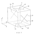
- the stress detection sensor 3 comprises a cubic base 2 and strain measuring means mounted thereon.
- the strain measuring means may, for example, be strain gauges.
- strain gauges 21-24 and 31-34 are represented by lines on respective planes of the base 20.
- the base 20 may for example be made of a plastic material such as epoxy resin.
- the strain gauges 21-24 and 31-34 are attached to the base 20 by bonding to the respective surfaces of the base 20 with an adhesive or being embedded in the surface regions of the base 20.
- Each of the strain gauges 21-24 and 31-34 is preferably mounted at an angle of 45 degrees with respect to Y-axis.
- the stress detection sensor 3 is inserted into the hole 2 and installed on the axle centerline (the center axis 5 of the axle).
- X, Y and Z axes are established in coincidence with the direction of advance of the vehicle 9, the direction of an axle 10 and a vertical direction 11, respectively.
- a top surface of the stress detection sensor (one side whose normal direction is Z direction) is preferably above the centerline of the axle, a bottom surface of the sensor (another side whose normal direction is Z direction) is preferably below the centerline of the axle.
- the magnitude of the tensile or the compressive strain due to the bending deformation generated by the road surface frictional force, vertical drag and side force acting on the wheel is preferably the same on the two surfaces of the stress detection sensor or the magnitude of shear strain associated with torsional deformation generated by brake torque on actuation of the brake is preferably the same on both surfaces.
- a front surface (one side whose normal direction is X direction) and a rear surface (another side whose normal direction is X direction) of the stress detection sensor be disposed on each side of the axle centerline respectively and the strain due to bending deflection or torsional deformation be the same on both surfaces.
- the hole 2 is then filled up with a filler 4 (an example of spacer means).
- the filler 4 is preferably of the same material as the stress detection sensor 3.
- the filler 4 fills up the gap around the stress detection sensor 3 in order to securely lock the sensor in the hole 2.
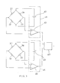
- the set of strain gauges 21, 22, 23 and 24 and the set of 31, 32, 33 and 34, of the strain detection sensor 3, are respectively connected into a bridge and these bridges are electrically connected to an amplification circuit 41 consisting of a direct current source 42 and an amplifier 43 and an amplification circuit 44 consisting of a direct current source 45 and an amplifier 46, respectively, through an electric signal line 8.
- an amplification circuit 41 consisting of a direct current source 42 and an amplifier 43
- an amplification circuit 44 consisting of a direct current source 45 and an amplifier 46, respectively, through an electric signal line 8.
- the strain gauges 21-24 detect this shear strain.
- the amplification circuit 41 outputs a voltage signal proportional to this shear strain, that is to say the road surface frictional force.
- the strain gauges 21-24 form a bridge and partly because the shear strain is detected in the neighborhood of the axle centerline, the output signal cross-talks due to bending deformation and torsional deformation can be held to minimum. In this manner, a device for measuring action force of a wheel capable of measuring road surface frictional force with high precision can be implemented.
- shear stress is generated in the planes of the front and rear sides of the stress detection sensor in response to the vertical drag acting on the wheel.
- the strain gauges 31-34 detect this shear strain.
- the amplification circuit 44 outputs a voltage signal proportional to this shear stress, that is to say vertical drag.
- Road surface friction coefficient can be determined by inputting output signals from the amplification circuits 41 and 44 to an operational circuit 47. In the operational circuit 47 road surface frictional force value is divided by vertical drag value to obtain road surface friction coefficient.
- each of the strain gauges 21-24 is preferably installed at an angle of 45 degrees with respect to Y-axis.
- the X, Y and Z axes in Fig. 4 are preferably coincident with a vertical direction 11, a direction of wheel advance 9 and an axle direction 10, respectively.
- the X, Y and Z axes in Fig. 4 are preferably coincident with the direction of wheel advance 9, the axle direction 10 and the vertical direction 11.
- the relationship of the sensor installation position to the axle centerline is the same as the stress detection sensor shown in Fig. 2.
- the strain gauges 21-24 are connected to the signal processing circuit shown in Fig. 5. Thus, they are formed into a bridge which, in turn, is connected to an amplification circuit 41. This amplification circuit 41 outputs a signal corresponding to road surface frictional force or vertical drag.
- a stress detection sensor illustrated in Fig. 6 is employed and the respective strain gauges 21-24 are provided so as to be oriented along Y-axis or Z-axis as illustrated.
- the axes X, Y and Z coincide with a direction of wheel advance 9, an axle direction 10 and a vertical direction 11 respectively, and the signal processing circuit is connected in the same manner as shown in Fig. 5.
- a device for measuring action force of a wheel for detecting side force acting on the wheel can be implemented.
- the stress detection sensor comprises strain measuring gauges 21-24 attached to a planner part 52 provided at one end of a bar-shaped structure 51.
- resistance strain gauges are used as the strain measuring gauges.
- the bar-shaped structure 51 may be made of a plastic material or of the same material as the axle 1 in which the sensor is embedded.
- the strain gauges 21, 22, 23 , and 24 are installed with their respective axes making an angle of 45 degrees with respect to a center axis 50 and fixedly mounted in the hole 2 formed in the axle 1. Thus, it can be mounted by tapping, adhesion, brazing, welding, shrinkage fitting or the like. Because of the bar-shaped structure, there is an advantage that the strain gauges can be easily set in predetermined positions and in predetermined orientations when the stress detection sensor 3 is installed and locked in the hole 2.
- the width of the planner part 52 is smaller than the diameter of the bar-shaped structure 51. For this reason, in installing and locking the stress detection sensor 3 in the hole 2, the occurrence of twisting or other deformation and consequent excessive straining or damage of the planner part 52 due to rotation or the like can be effectively prevented.
- Fig. 9 is an enlarged diagrammatic view showing the hole 2 formed in the axle.
- two stress detection sensors 3 shown in Fig. 4 are employed.
- X, Y and Z axes are established in coincidence with a vertical direction 11, a direction of wheel advance 9 and an axle direction 10, respectively.
- the sets of strain gauges of 21-24 and 21-24 of each stress detection sensor 3 are connected in the same manner as in the signal processing circuit shown in Fig. 3, whereby road surface frictional force and either drive torque acting on the wheel or brake torque when the brake system is actuated can be outputted.
- an operational circuit 47 can give road surface frictional force by addition and torque by subtraction.
- one of the stress detection sensors 3 is set on the center axis 5 of the axle but the same result is obtained when both sensors are offset from the center axis 5.
- Fig. 10 is an embodiment for measuring road surface frictional force, wherein an amplification circuit 41 and a stress detection sensor 3 are securely mounted together in a hole 2. Installation of the amplification circuit 41 in the hole 2 can be effected in the contemporary circuit integration technology. By disposing the amplification circuit 41 in close proximity to the stress detection sensor 3, a noise-lean output signal can be made available on the signal line 53.
- Fig. 11 shows an embodiment for measuring road surface frictional force with a system wherein the axle is formed with a horizontal hole and the amplification circuit 41 and the stress detection sensor 3 are provided together in the hole, just as in the embodiment shown in Fig. 10.
- Fig 12 shows an embodiment of a device for measuring road surface frictional force and either drive torque or brake torque, all of which act on the wheel, by means of two stress detection sensors 3, wherein a signal processing circuit 54 comprising amplification circuits 41 and 44 and an operational circuit 47 is installed together with the stress detection sensor 3 in the hole.
- the numeral 55 indicates an output signal line of the signal processing circuit 54.
- Fig. 13 shows an embodiment of measuring brake torque or drive torque with a single stress detection sensor 3.
- the strain gauges 21, 22, 23 and 24 are connected in the same manner as shown in Fig. 5 except that 22 and 23 are exchanged, viz. in the order of 21, 23, 22 and 24, whereby a device for measuring the above-mentioned torque is implemented.
- Fig. 1 Shown in Fig. 1 is an embodiment in which the hole 2 for accepting the stress detection sensor 3 is formed along the vertical direction 11.
- the orientation of the hole 2 is optional, of course.
- the hole 2 can be formed in the horizontal direction, e.g. along the direction of advance 9 of the wheel.
- Figs. 1 and 9 - 13 show an embodiments wherein the stress detection sensor 3 is fixedly embedded in the hole 2 by means of the filler 4.
- a stress detection sensor 3 which is made of plastic or metal disc base of the approximately the same diameter as the inner diameter of the hole 2 and is attached with the strain gauges at the top and bottom thereon can be inserted and embedded in the hole 2 with the contact surfaces being fixed by means of sealers or adhesives.
- a stress detection sensor 3 which is made of plastic or metal planner base having approximately the same width as the inner diameter of the hole 2 and is attached with the strain gauges at the top and bottom thereon can be inserted and embedded in the hole 2 and the contact surfaces can be fixed by means of sealers or adhesives.
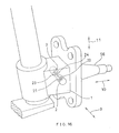
- Fig. 14 shows an embodiment in which the hole 2 is provided in the axle direction 10. Moreover, the position of the hole is not limited to the position of the knuckle but may be a leading position of the axle, that is to say at the spindle 56.
- the embodiment illustrated in Fig. 14 is advantageous in that simply by installing the same type stress detection sensor as that shown in Fig. 7 or 8 in the altered orientation, it can serve not only as a device for measuring road surface frictional force but also as a device for measuring vertical drag.
- Fig. 15 shows a still another embodiment of a device for measuring action force of a wheel.
- resistance strain gauges as stress detection sensors are mounted on the axle of a driven wheel of a vehicle having strut type suspension structure which is often employed in automobiles.
- the wheel action force to be measured is road surface frictional force.
- the holes 2 preferably extends from the top and bottom of the axle in the direction 11 perpendicular to the road surface and intersecting the centerline of the axle.
- the diameter of each hole 2 may for example be about 5 mm to about 10 mm.
- the bottom surface of each hole 2 preferably lies close to the axle centerline. For example, the distance between the respective bottom surfaces in the neighborhood of the axle centerline may be about 1 mm.
- the hole 2 formed from the top side be disposed above the axle centerline and the hole 2 formed from the bottom side be disposed below the axle centerline and that the magnitude of tensile or compressive stress associated with bending deformation due to road surface frictional force and vertical drag acting on the wheel be the same on both bottom surfaces or the magnitude of shear strain associated with torsional deformation due to brake torque on actuation of the brake be the same on both bottom surfaces. This is of increased significance when the distance between the two bottom surfaces is large.
- Resistance strain gauges are attached to each of the bottom surfaces in the following manner.
- Four resistance strain gauges are provided and affixed to each bottom surfaces, two per bottom. They are so attached that each strain gauge makes an angle of 45 degrees with respect to the direction of the spindle center axis 10.
- These strain gauges 21-24 has a bridge circuit in the same manner as in the signal processing circuit shown in Fig. 5 and the bridge is connected to an amplification circuit 41.
- shear strain In response to road surface frictional force acting on the wheel, shear strain is generated in the plane of the bottom surface of each hole.
- the strain gauges detect this shear strain.
- the amplification circuit 41 outputs a voltage signal proportional to this shear strain, that is to say road surface frictional force.
- the strain gauges 21-24 can be protected against the external environment.
- Fig. 16 shows a still another embodiment of a device for measuring action force of a wheel.
- vertical drag as wheel action force is measured.
- resistance strain gauges as strain measuring gauges are attached to the axle of a driven wheel of a vehicle having strut type suspension structure.
- the holes are preferably formed in such a manner that they extend from both sides of the axle in mutual alignment in the direction of advance 9 of the wheel and intersect the centerline of the axle.
- the diameter of each hole may for example be about 5 mm to about 10 mm just as in the case of the device for measuring road surface frictional force.
- the bottom surface of each hole preferably lies close to the axle centerline. For example, the distance between the respective bottom surfaces in the neighborhood of the axle centerline may be about 1 mm.
- the hole extending from the front side be disposed forwardly of the axle centerline while the hole extending from the rear side be disposed rearwardly of the axle centerline and that the magnitude of tensile or compressive strain due to bending deformation caused by road surface frictional force and vertical drag acting on the wheel be the same on the two bottom surfaces or the magnitude of shear stress due to torsional deformation caused by brake torque on actuation of the brake be the same on the two bottom surfaces.
- Resistance strain gauges are affixed to each of the bottom surfaces in the following manner. Thus, four resistance strain gauges are provided and affixed to the respective bottom surface, two per bottom.
- Each of the strain gauges is disposed to make an angle of 45 degrees with respect to the direction 11 perpendicular to the road surface.
- These strain gauges 21-24 has a bridge circuit as shown in the signal processing circuit of Fig. 5 and the bridge circuit is connected to an amplification circuit 41.
- the amplification circuit 41 outputs a voltage signal proportional to this shear stress, that is to say the vertical drag. Because the holes 2 are formed in the axle and shear strain is detected in the vicinity of the axle centerline, the output signal crosstalk due to bending deformation or torsional deformation can be held to a minimum. Thus, a vertical drag detecting device with high precision is implemented.
- synthetic resin e.g. epoxy resin, or other space means, the strain gauges can be protected against the external environment.
- a device for measuring action force of a wheel for determining road surface friction coefficient can be implemented.
- the center axis of the holes extending in up-and-down direction in the road surface frictional force measuring device and the center axis of the holes extending in front-and-rear direction in the vertical drag measuring device are close to each other or intersecting each other, the bottom surfaces of at least one of these two pairs of holes must be at a certain distance from the centerline of the axle. Provided that the above-mentioned two center axes are sufficiently apart, the bottom surfaces of any pair can be disposed in the vicinity of the axle centerline.
- this device for measuring road surface friction coefficient Since this is a combination of the road surface frictional force measuring device and the vertical drag measuring device, this device for measuring road surface friction coefficient has the characteristics of the two constituent devices. Thus, for the reasons mentioned hereinbefore, a device for measuring road surface friction coefficient with high precision and with a minimum crosstalk can be implemented.
- the principle of measuring various acting forces on the wheel at the axle is to detect strains produced in the axle by means of the embedded strain gauges. Therefore, by modifying the procedure of measuring forces acting on the wheel at the axle, stresses generated in any desired structures can be easily measured.
- An embodiment of such an application is shown in Fig. 17.
- the same stress detection sensor as shown in Fig. 6 is inserted into a hole 61 formed in a structure 60 and the gap in the hole 61 is filled up with a filler 62.
- This embodiment is a measuring device applicable to the case in which plane strain with main strain having a known direction is generated in the measurement part of the structure 60.
- X, Y represent the directions of the main strain.
- the technology of measuring stress or load with an embedded stress detection sensor carrying strain gauges is advantageous in that by installing the stress detection sensor in a hole in a proper orientation according to a target strain or load, any stress or load can be successfully measured.
- Fig. 18 shows a measuring device applicable when the direction of main strain at the measurement part of a structure is unknown.
- the stress detection sensor 3 illustrated in Fig. 19 is employed.
- strain gauges 71-79 constitute a triaxial rosette gauge and the distribution of stress in three axial directions can be measured by a known technique using a rosette gauge.
- the stress detection sensor 3 illustrated in Fig. 19 can be employed.
- stress generated in the knuckle in correspondence with road surface frictional force, vertical drag and other wheel action forces can be measured. In other words, any desired wheel action forces can be measured.
- a load measuring device can be implemented.
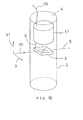
- a typical embodiment of the applications is shown in Fig. 10.
- a pillar-shaped element 80 of stainless steel or the like is formed with a hole 81 and a stress detection sensor 3 is inserted therein and the hole is secured by a filler 82.
- the stress detection sensor 3 shown in Fig. 4 is employed.
- the load 83 to be measured can be determined.
- the reference numeral 84 indicates holes for fixing the load measuring device in position. While this is only one of embodiments, an expedient load measuring device can be implemented by applying the principle of the device for measuring stress of a structure.
- the stress generated in the structure 60 can be measured.
- this structure 60 is made of the same material as the bar-shaped structure 51 having the stress detection sensor. It is fixedly secured by the same procedure for mounting on the axle 1 as described hereinbefore. And the signal processing circuit shown in Fig. 5 is used in conjunction.
- the stress detection sensor shown in Fig. 7 or 8 the shear strain generated in the object structure in a direction perpendicular to the center axis 50 or compressive or tensile strain in the direction of strain gauges is measured.
- strains of various kinds generated in the object structure in various directions can be measured by varying attaching orientation of the strain measuring gauges.
- Another advantage is that, by drilling the hole 61 in an optional position of the object structure 60, strains in an optional position can be measured by using the same kind of stress detection sensor.
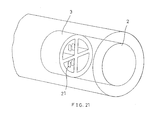
- a known load converter (load cell) shown in Fig. 21 can be directly embedded in lieu of the above-mentioned stress detection sensor 3.
- a stress detection sensor in a hole and measuring the strain generated in an object or the load acting on the object and particularly modifying or amplifying the foregoing embodiments wherein the force, the torque or the coefficient of friction acting on the wheel are measured at the axle, devices for measuring a diversity of stresses in various objects or devices for measuring a diversity of loads, torques, etc. acting on an object can be implemented.
Abstract
Description
- The present invention relates to a device for measuring action force of a wheel for detecting road surface frictional force, vertical drag, road surface friction coefficient, etc. which can be a constituent element of a brake system with skid control for preventing lock (seizure) of the wheels of a vehicle on sudden stops or a traction control system for preventing excessive slip of the wheels at acceleration, and a device for measuring stress of a structure for measuring stresses produced in optional structures.
- The antilock brake system (ABS) of a conventional vehicle such as an automobile generally employs a principle of automatically controlling brake action, according to chassis speed and wheel speed, in such a manner that slip ratio falls into a certain range (cf. JP-B-59-30585 and JP-A-60-61354). The relationship between road surface friction coefficient and slip ratio is variable according to road surface conditions. Therefore, in the above-mentioned system, braking force may not be maximum depending on road surface conditions and a minimum braking distance cannot be obtained in such a case. Furthermore, since the chassis speed is estimated from the wheel speed, control of the slip ratio is deficient in precision. Exact determination of the chassis speed requires a complicated apparatus such as a ground-relative speed sensor (cf. JP-A-63-64861), a chassis deceleration sensor (cf. JP-A-63-170157) or the like.
- There was accordingly proposed an ABS which takes into account road surface frictional force or road surface friction coefficient as a measured value. In the system described in JP-A-63-25169, the torque (tire torque) of the road surface frictional force acting on the wheels is obtained by operating the wheel angular acceleration speed and the brake fluid pressure. And the beginning of decline in the tire torque while the brake fluid pressure increases is adopted as one of the criteria for the assessment of wheel conditions just before the wheels are locked. However, in this system, the tire torque is indirectly determined by arithmetic operations of the wheel angular acceleration speed and the brake fluid pressure, and wheel inertia efficiency and the braking efficiency of a brake and so on are indefinite constants. Therefore, the precision of the calculated values is not sufficiently high.
- Regarding a traction control system, the conventional apparatus also detects the wheel slip at the time of acceleration by measuring wheel speed like the ABS. In this case, too, there is the same problem as in the ABS wherein controls are executed based on wheel speed.
- Therefore, constituent elements of these new ABS or traction control system, there is a demand for an apparatus for measuring dynamic quantities relating to the interaction between road surface and wheels such as road surface frictional force, vertical drag and road surface friction coefficient.
- An object of the present invention to meet the above-mentioned demand is to provide a device for measuring the action force of wheels for detecting road surface frictional force, vertical drag and road surface friction coefficient, and to provide a structure stress measuring apparatus for measuring the stresses generated in structures.
- The present invention provides a wheel action force measuring apparatus comprising a stress detection sensor securely mounted in a hole provided in a vehicle axle and a signal processing circuit adapted to process the detection signals from the stress detection sensor.
- According to such a device, the stress of the axle due to wheel action force is detected by the stress detection sensor. The stress is proportional to the wheel action force and, therefore, the stress detection sensor detects the wheel action force through the stress. Since the stress detection sensor is embedded in the axle, interferences to sensor output signals from wheel action forces other than target wheel action force can be decreased and, moreover, the sensor can be protected against the external environment. Furthermore, since the detection signal from the stress detection sensor is processed by the signal processing circuit, interferences from wheel action forces other than the specific wheel action force subjected to measurement can be further decreased.
- According to the above-mentioned device for measuring the action force of a wheel, the hole in the axle can be disposed in alignment with the stress neutral line of the axle. According to such an alignment, the interferences to the sensor output signals from the brake torque, side force, etc. acting on the wheel can be effectively decreased.
- In the above-mentioned device for measuring action force of a wheel, the stress detection sensor can be disposed on the centerline of the axle, whereby the interferences to the sensor output signal from the brake torque, side force, etc. acting on the wheel can be decreased.
- Furthermore, the present invention provides a device for measuring action force of a wheel comprising a plurality of stress detection sensors independently securely embedded in a plurality of holes in a vehicle axle and a signal processing circuit adapted to process detection signals from each of the stress detection sensors to extract a specified stress. According to the above-mentioned arrangement, a specific action force among various wheel action forces such as road surface frictional force, vertical drag, brake torque, side force, etc. can be measured, with influences of the other action forces being decreased.
- According to any of the above-mentioned wheel action measuring apparatuses, the detection sensor and the signal processing circuit can be securely installed together in the hole of the axle. Therefore, a high signal-to-noise ratio can be achieved in the output signal from the signal processing circuit.
- Furthermore, the present invention provides a device for measuring action force of a wheel comprising stress detection sensors securely installed in each of the holes formed in horizontal and vertical directions in the axle and a signal processing circuit adapted to process a detection signal from each of the stress detection sensors. In this arrangement, road surface frictional force and vertical drag acting on a wheel can be measured by the stress detection sensors and the detection signal from each of the stress detection sensors can be processed in the signal processing circuit to measure road surface friction coefficient which is defined as the ratio of road surface frictional force and vertical drag.
- In any of the above-mentioned devices for measuring action force of a wheel, the stress detection sensor can be constructed as an integral unit comprising strain gauges mounted on a cubic plastic base. In this arrangement, the stress detection sensors can measure road surface frictional force and vertical drag acting on a wheel at generally the same position in the axle. Thus, the stress detection sensors can be installed in a position in the axle where interferences to two measured values from wheel action forces other than those wheel action forces can be simultaneously decreased.
- In any of the devices for measuring action force of a wheel as mentioned above, the stress detection sensor can be constructed as an integral unit comprising strain gauges mounted on a planner part provided at one end of a bar-shaped structure. In this arrangement, the stress detection sensor can be easily embedded in a predetermined position and in a predetermined orientation in the hole.
- In any of the above-mentioned devices for measuring action force of a wheel, the stress detection sensor can be constructed as an integral unit which has strain gauges mounted on a ceramic substrate and is covered up with an oxide film. In this arrangement, a highly heat-resistant stress detection sensor can be constituted.
- In any of the devices for measuring action force of a wheel as mentioned above, the strain gauges of each of the stress detection sensors can be securely mounted in the hole of the axle in an orientation of about 45 degrees with respect to the horizontal and vertical stress center axes of the axle. Therefore, the respective sensors can measure road surface frictional force and vertical drag acting on the wheel, with interferences from other wheel action forces being decreased.
- Furthermore, the present invention provides a device for measuring action force of a wheel comprising an auxiliary stress detection sensor for detecting brake torque etc., of which auxiliary stress detection sensor disposed in the vicinity of a main stress sensor in the hole formed in the vehicle axle, and the signal processing circuit for processing stress detection signal from these sensors, thereby eliminating or decreasing brake torque and other strain signals.
- The present invention further provides a device for measuring stress of a structure comprising a stress detection sensor securely mounted in a hole formed in a structure to be measured the stress thereof and a signal processing circuit for processing the detection signals from the stress detection sensor. Because of this arrangement, stresses in any desired position including the interior of the structure can be measured.
- In any of the devices for measuring action force of a wheel as mentioned above, the signal processing circuit can be constituted of a sensor bridge circuit for stress detection and an amplification circuit. In this arrangement, interferences from wheel action forces other than a specific wheel action force can be effectively eliminated and, in addition, the sensitivity of the stress detection sensor be increased so that a sufficiently large output of the measured wheel action force can be obtained.
- In any of the devices for measuring action force of a wheel as mentioned above, the signal processing circuit can consist of a sensor bridge circuit for stress detection, an amplification circuit and an operational circuit. In this arrangement, interferences from wheel action forces other than a specific wheel action force can be effectively eliminated and the sensitivity of the stress detection sensor be increased, with the result that it is not only possible to obtain a measured value of the desired wheel action force as a sufficiently large output but also possible to determine road surface friction coefficient which is defined as the ratio of road surface frictional force and vertical drag.
- In any of the wheel action measuring devices as mentioned above, the signal processing circuit can consist of a sensor bridge circuit for stress detection.
- The effects of the present invention are as follows.
- According to the device of the present invention, road surface frictional force, vertical drag, road surface friction coefficient, side force, brake torque, drive torque, etc can be easily measured. When the device is utilized in an antilock brake system, the braking distance can be reduced as much as possible regardless of road surface conditions and, at the same time, the object of antilock can be accomplished. Moreover, there is no need for a complicated apparatus for measuring the chassis speed. In a traction control device, the acceleration distance can be reduced as mush as possible regardless of road surface conditions. Thus, the present invention brings forth remarkable improvements in the performance of a vehicle antilock brake system and a traction control device.
- Furthermore, according to the device of the present invention, the stress of a structure can be easily measured. In addition, any load, torque or the like can be also expediently measured.
- In accordance with the present invention, the technology for measuring stresses, loads or the like by means of a stress detection sensor with strain gauges embedded in an optional structure offers such effects that, by positioning the stress detection sensor in a suitable orientation in a hole according to a target stress or load, any desired stress, load or the like can be measured . Moreover, by placing a plurality of stress detection sensors in suitable positions and orientations, overlapping stresses or loads can be eliminated or decreased and the necessary stress or load be extracted and measured. Furthermore, this stress measuring device has an additional advantage that the stresses generated internally in an object structure can be easily measured.
-
- Fig. 1 is a partial perspective view showing an embodiment of a device for measuring action force of a wheel according to the present invention.
- Fig. 2 is a partial perspective view showing an embodiment of a stress detection sensor of a device for measuring action force of a wheel according to the present invention.
- Fig. 3 is a diagrammatic view showing an embodiment of a signal processing circuit of a device for measuring action force of a wheel according to the present invention.
- Fig. 4 is a partial perspective view showing another embodiment of a stress detection sensor of a device for measuring action force of a wheel according to the present invention.
- Fig. 5 is a diagrammatic view showing another embodiment of a signal processing circuit of a device for measuring action force of a wheel according to the present invention.
- Fig. 6 is a partial perspective view showing still another embodiment of a stress detection sensor of a device for measuring action force of a wheel according to the present invention.
- Fig. 7 is a partial perspective view showing a stress detection sensor consisting of another embodiment of a device for measuring action force of a wheel.
- Fig. 8 is a partial perspective view showing another embodiment of a stress detection sensor consisting of still another embodiment of a device for measuring action force of a wheel.
- Fig. 9 is a perspective interior view showing an embodiment wherein a plurality of stress detection sensors are employed in a device for measuring road surface frictional force and brake torque or drive torque as wheel action forces.
- Fig. 10 is a perspective interior view showing an embodiment wherein a signal processing circuit and a stress detection sensor are securely mounted in the same hole according to a device for measuring road surface frictional force as a wheel action force.
- Fig. 11 is a perspective interior view showing an embodiment wherein a signal processing circuit and a stress detection sensor are securely mounted in a same horizontal hole according to a device for measuring road surface frictional force as a wheel action force.
- Fig. 12 is a perspective interior view showing an embodiment wherein a plurality of stress detection sensors and a signal processing circuit are securely mounted in a same hole according to a device for measuring road surface frictional force and brake torque or drive torque as wheel action forces.
- Fig. 13 is a perspective interior view showing an embodiment of a stress detection sensor of a device for measuring brake torque or drive torque as a wheel action force.
- Fig. 14 is a partial perspective view showing an embodiment of a hole for supporting a stress detection sensor of a device for measuring action force of a wheel according to the present invention.
- Fig. 15 is a partial perspective interior view showing installation state of a stress detection sensor consisting another embodiment of a device for measuring road surface frictional force as a wheel action force.
- Fig. 16 is a partial perspective interior view showing installation state of a stress detection sensor consisting another embodiment of a device for measuring vertical drag as a wheel action force.
- Fig. 17 is a perspective interior view showing another embodiment of a device for measuring stress of a structure.
- Fig. 18 is a perspective interior view showing still another embodiment of a device for measuring stress of a structure.
- Fig. 19 is a perspective view showing another embodiment of a stress detection sensor equipped with strain gauges.
- Fig. 20 is a perspective interior view showing an embodiment of a load measuring device as a device for measuring stress of a structure.
- Fig. 21 is a perspective view showing the prior art provided with a embedded load converter.
- Fig. 22 is a partial perspective view of another embodiment showing installation state of a stress detection sensor.
- Fig. 23 is a partial perspective view of still another embodiment showing installation state of a stress detection sensor.
- The followings are preferred embodiments of the present invention and should by no means be construed as limiting the scope of the invention as defined in the claims.
- Embodiments of a device for measuring action force of a wheel for determining road surface friction coefficient are shown in Figs. 1, 2 and 3. Fig. 1 shows installation state of a stress detection sensor. Fig. 2 shows the stress detection sensor and Fig. 3 shows a signal processing circuit. As an example, there is shown a case in which the stress detection sensor is mounted in an axle of a driven wheel of a car having strut type suspension structure which is often used for automobiles. From the top to bottom of an axle 1 (a knuckle in this example), a
hole 2 is formed along adirection 11 perpendicular to a road surface and intersecting an axle centerline (a stress neutral line) of the axle. The diameter of thehole 2 may, for example, be about 5 mm to about 10 mm. Here, the axle centerline (a stress neutral line) means the centerline of bending deformation generated in theaxle 1 by road surface frictional force, vertical drag and side force acting on the wheel rotating about a spindle (the line on which neither tensile strain nor compressive strain occurs due to bending deformation), or the centerline of torsional deformation which is generated in theaxle 1 by brake torque on actuation of a brake (the line on which no shear strain is generated by torsional deformation). These centerlines approximately coincide with the centerline of a spindle (acenter axis 5 of the axle). Astress detection sensor 3 is inserted into thehole 2. As shown in Fig. 2, thestress detection sensor 3 comprises acubic base 2 and strain measuring means mounted thereon. The strain measuring means may, for example, be strain gauges. As illustrated, strain gauges 21-24 and 31-34 are represented by lines on respective planes of thebase 20. The base 20 may for example be made of a plastic material such as epoxy resin. The strain gauges 21-24 and 31-34 are attached to thebase 20 by bonding to the respective surfaces of the base 20 with an adhesive or being embedded in the surface regions of thebase 20. Each of the strain gauges 21-24 and 31-34 is preferably mounted at an angle of 45 degrees with respect to Y-axis. Thestress detection sensor 3 is inserted into thehole 2 and installed on the axle centerline (thecenter axis 5 of the axle). X, Y and Z axes are established in coincidence with the direction of advance of thevehicle 9, the direction of anaxle 10 and avertical direction 11, respectively. A top surface of the stress detection sensor (one side whose normal direction is Z direction) is preferably above the centerline of the axle, a bottom surface of the sensor (another side whose normal direction is Z direction) is preferably below the centerline of the axle. The magnitude of the tensile or the compressive strain due to the bending deformation generated by the road surface frictional force, vertical drag and side force acting on the wheel is preferably the same on the two surfaces of the stress detection sensor or the magnitude of shear strain associated with torsional deformation generated by brake torque on actuation of the brake is preferably the same on both surfaces. This is of increased significance when the distance between the top and bottom surfaces is large. It is also preferable that a front surface (one side whose normal direction is X direction) and a rear surface (another side whose normal direction is X direction) of the stress detection sensor be disposed on each side of the axle centerline respectively and the strain due to bending deflection or torsional deformation be the same on both surfaces. Thehole 2 is then filled up with a filler 4 (an example of spacer means). Thefiller 4 is preferably of the same material as thestress detection sensor 3. Thefiller 4 fills up the gap around thestress detection sensor 3 in order to securely lock the sensor in thehole 2. By the above-mentioned procedure, the strain gauges 21-24 and 31-34 are embedded securely in the predetermined position and in the predetermined orientation in thehole 2. - Like a signal processing circuit shown in Fig. 3, the set of
strain gauges strain detection sensor 3, are respectively connected into a bridge and these bridges are electrically connected to anamplification circuit 41 consisting of a directcurrent source 42 and anamplifier 43 and anamplification circuit 44 consisting of a directcurrent source 45 and anamplifier 46, respectively, through anelectric signal line 8. In response to the road surface frictional force acting on the wheel, shear strain is generated in the planes of the top and bottom surfaces of the stress detection sensors. The strain gauges 21-24 detect this shear strain. Theamplification circuit 41 outputs a voltage signal proportional to this shear strain, that is to say the road surface frictional force. Partly because the strain gauges 21-24 form a bridge and partly because the shear strain is detected in the neighborhood of the axle centerline, the output signal cross-talks due to bending deformation and torsional deformation can be held to minimum. In this manner, a device for measuring action force of a wheel capable of measuring road surface frictional force with high precision can be implemented. Similarly, shear stress is generated in the planes of the front and rear sides of the stress detection sensor in response to the vertical drag acting on the wheel. The strain gauges 31-34 detect this shear strain. Theamplification circuit 44 outputs a voltage signal proportional to this shear stress, that is to say vertical drag. Partly because the strain gauges 31-34 form a bridge and partly because the shear strain is detected in the neighborhood of the axle centerline, the output signal cross-talk due to bending deformation and torsional deformation can be minimized. In this manner, a device for measuring action force of a wheel capable of measuring vertical drag with high precision is implemented. Road surface friction coefficient can be determined by inputting output signals from theamplification circuits operational circuit 47. In theoperational circuit 47 road surface frictional force value is divided by vertical drag value to obtain road surface friction coefficient. - In this embodiment, since the gap around the
stress detection sensor 3 in thehole 2 is filled up with synthetic resin, e.g. epoxy resin, or other spacer means, an additional advantage is realized such that the strain gauges 21-24 and 31-34 are protected against the external environment. - In order to measure either road surface frictional force or vertical drag, the
stress detection sensor 3 illustrated in Fig. 4 can be employed in lieu of thestress detection sensor 3 of Fig. 2. Thus, each of the strain gauges 21-24 is preferably installed at an angle of 45 degrees with respect to Y-axis. - For the purpose of measuring road surface frictional force, the X, Y and Z axes in Fig. 4 are preferably coincident with a
vertical direction 11, a direction ofwheel advance 9 and anaxle direction 10, respectively. For the purpose of measuring vertical drag, the X, Y and Z axes in Fig. 4 are preferably coincident with the direction ofwheel advance 9, theaxle direction 10 and thevertical direction 11. The relationship of the sensor installation position to the axle centerline is the same as the stress detection sensor shown in Fig. 2. The strain gauges 21-24 are connected to the signal processing circuit shown in Fig. 5. Thus, they are formed into a bridge which, in turn, is connected to anamplification circuit 41. Thisamplification circuit 41 outputs a signal corresponding to road surface frictional force or vertical drag. - For the purpose of measuring side forces as a wheel action force, a stress detection sensor illustrated in Fig. 6 is employed and the respective strain gauges 21-24 are provided so as to be oriented along Y-axis or Z-axis as illustrated. Here, the axes X, Y and Z coincide with a direction of
wheel advance 9, anaxle direction 10 and avertical direction 11 respectively, and the signal processing circuit is connected in the same manner as shown in Fig. 5. In this manner, a device for measuring action force of a wheel for detecting side force acting on the wheel can be implemented. - Other embodiments of a stress detection sensor are shown in Figs. 7 and 8. In these embodiments, the stress detection sensor comprises strain measuring gauges 21-24 attached to a
planner part 52 provided at one end of a bar-shapedstructure 51. Here, too, resistance strain gauges are used as the strain measuring gauges. The bar-shapedstructure 51 may be made of a plastic material or of the same material as theaxle 1 in which the sensor is embedded. The strain gauges 21, 22, 23 , and 24 are installed with their respective axes making an angle of 45 degrees with respect to acenter axis 50 and fixedly mounted in thehole 2 formed in theaxle 1. Thus, it can be mounted by tapping, adhesion, brazing, welding, shrinkage fitting or the like. Because of the bar-shaped structure, there is an advantage that the strain gauges can be easily set in predetermined positions and in predetermined orientations when thestress detection sensor 3 is installed and locked in thehole 2. - Particularly, in the case shown in Fig, 8, the width of the
planner part 52 is smaller than the diameter of the bar-shapedstructure 51. For this reason, in installing and locking thestress detection sensor 3 in thehole 2, the occurrence of twisting or other deformation and consequent excessive straining or damage of theplanner part 52 due to rotation or the like can be effectively prevented. - Fig. 9 is an enlarged diagrammatic view showing the
hole 2 formed in the axle. In this embodiment, twostress detection sensors 3 shown in Fig. 4 are employed. X, Y and Z axes are established in coincidence with avertical direction 11, a direction ofwheel advance 9 and anaxle direction 10, respectively. The sets of strain gauges of 21-24 and 21-24 of eachstress detection sensor 3 are connected in the same manner as in the signal processing circuit shown in Fig. 3, whereby road surface frictional force and either drive torque acting on the wheel or brake torque when the brake system is actuated can be outputted. Using the output signals from twoamplification circuits operational circuit 47 can give road surface frictional force by addition and torque by subtraction. In this embodiment, one of thestress detection sensors 3 is set on thecenter axis 5 of the axle but the same result is obtained when both sensors are offset from thecenter axis 5. - Fig. 10 is an embodiment for measuring road surface frictional force, wherein an
amplification circuit 41 and astress detection sensor 3 are securely mounted together in ahole 2. Installation of theamplification circuit 41 in thehole 2 can be effected in the contemporary circuit integration technology. By disposing theamplification circuit 41 in close proximity to thestress detection sensor 3, a noise-lean output signal can be made available on thesignal line 53. - Fig. 11 shows an embodiment for measuring road surface frictional force with a system wherein the axle is formed with a horizontal hole and the
amplification circuit 41 and thestress detection sensor 3 are provided together in the hole, just as in the embodiment shown in Fig. 10. - Fig 12 shows an embodiment of a device for measuring road surface frictional force and either drive torque or brake torque, all of which act on the wheel, by means of two
stress detection sensors 3, wherein asignal processing circuit 54 comprisingamplification circuits operational circuit 47 is installed together with thestress detection sensor 3 in the hole. The numeral 55 indicates an output signal line of thesignal processing circuit 54. - Fig. 13 shows an embodiment of measuring brake torque or drive torque with a single
stress detection sensor 3. The strain gauges 21, 22, 23 and 24 are connected in the same manner as shown in Fig. 5 except that 22 and 23 are exchanged, viz. in the order of 21, 23, 22 and 24, whereby a device for measuring the above-mentioned torque is implemented. - Shown in Fig. 1 is an embodiment in which the
hole 2 for accepting thestress detection sensor 3 is formed along thevertical direction 11. However, the orientation of thehole 2 is optional, of course. For example, thehole 2 can be formed in the horizontal direction, e.g. along the direction ofadvance 9 of the wheel. Figs. 1 and 9 - 13 show an embodiments wherein thestress detection sensor 3 is fixedly embedded in thehole 2 by means of thefiller 4. However, as shown in Fig. 22, astress detection sensor 3 which is made of plastic or metal disc base of the approximately the same diameter as the inner diameter of thehole 2 and is attached with the strain gauges at the top and bottom thereon can be inserted and embedded in thehole 2 with the contact surfaces being fixed by means of sealers or adhesives. - And also as shown in Fig. 23, a
stress detection sensor 3 which is made of plastic or metal planner base having approximately the same width as the inner diameter of thehole 2 and is attached with the strain gauges at the top and bottom thereon can be inserted and embedded in thehole 2 and the contact surfaces can be fixed by means of sealers or adhesives. - Fig. 14 shows an embodiment in which the
hole 2 is provided in theaxle direction 10. Moreover, the position of the hole is not limited to the position of the knuckle but may be a leading position of the axle, that is to say at thespindle 56. The embodiment illustrated in Fig. 14 is advantageous in that simply by installing the same type stress detection sensor as that shown in Fig. 7 or 8 in the altered orientation, it can serve not only as a device for measuring road surface frictional force but also as a device for measuring vertical drag. - Fig. 15 shows a still another embodiment of a device for measuring action force of a wheel. There is shown an embodiment in which resistance strain gauges as stress detection sensors are mounted on the axle of a driven wheel of a vehicle having strut type suspension structure which is often employed in automobiles. In this embodiment, the wheel action force to be measured is road surface frictional force.
- The
holes 2 preferably extends from the top and bottom of the axle in thedirection 11 perpendicular to the road surface and intersecting the centerline of the axle. The diameter of eachhole 2 may for example be about 5 mm to about 10 mm. The bottom surface of eachhole 2 preferably lies close to the axle centerline. For example, the distance between the respective bottom surfaces in the neighborhood of the axle centerline may be about 1 mm. It is preferable that thehole 2 formed from the top side be disposed above the axle centerline and thehole 2 formed from the bottom side be disposed below the axle centerline and that the magnitude of tensile or compressive stress associated with bending deformation due to road surface frictional force and vertical drag acting on the wheel be the same on both bottom surfaces or the magnitude of shear strain associated with torsional deformation due to brake torque on actuation of the brake be the same on both bottom surfaces. This is of increased significance when the distance between the two bottom surfaces is large. - Resistance strain gauges are attached to each of the bottom surfaces in the following manner. Four resistance strain gauges are provided and affixed to each bottom surfaces, two per bottom. They are so attached that each strain gauge makes an angle of 45 degrees with respect to the direction of the
spindle center axis 10. These strain gauges 21-24 has a bridge circuit in the same manner as in the signal processing circuit shown in Fig. 5 and the bridge is connected to anamplification circuit 41. In response to road surface frictional force acting on the wheel, shear strain is generated in the plane of the bottom surface of each hole. The strain gauges detect this shear strain. Theamplification circuit 41 outputs a voltage signal proportional to this shear strain, that is to say road surface frictional force. Partly because the axle is bored to make theholes 2 and shear strain is detected in the vicinity of the axle centerline and partly because the strain gauges constitute a bridge, the output signal crosstalk due to bending deformation or torsional deformation can be minimized. Thus a device for measuring road surface frictional force with high precision is implemented. Furthermore, by filling theholes 2 with synthetic resin, e.g. epoxy resin, or other space means, the strain gauges 21-24 can be protected against the external environment. - Fig. 16 shows a still another embodiment of a device for measuring action force of a wheel. In this embodiment, vertical drag as wheel action force is measured. Also in this embodiment resistance strain gauges as strain measuring gauges are attached to the axle of a driven wheel of a vehicle having strut type suspension structure. As illustrated, the holes are preferably formed in such a manner that they extend from both sides of the axle in mutual alignment in the direction of
advance 9 of the wheel and intersect the centerline of the axle. The diameter of each hole may for example be about 5 mm to about 10 mm just as in the case of the device for measuring road surface frictional force. The bottom surface of each hole preferably lies close to the axle centerline. For example, the distance between the respective bottom surfaces in the neighborhood of the axle centerline may be about 1 mm. It is preferable that the hole extending from the front side be disposed forwardly of the axle centerline while the hole extending from the rear side be disposed rearwardly of the axle centerline and that the magnitude of tensile or compressive strain due to bending deformation caused by road surface frictional force and vertical drag acting on the wheel be the same on the two bottom surfaces or the magnitude of shear stress due to torsional deformation caused by brake torque on actuation of the brake be the same on the two bottom surfaces. This is of increased significance when the bottom-to-bottom distance is large. Resistance strain gauges are affixed to each of the bottom surfaces in the following manner. Thus, four resistance strain gauges are provided and affixed to the respective bottom surface, two per bottom. Each of the strain gauges is disposed to make an angle of 45 degrees with respect to thedirection 11 perpendicular to the road surface. These strain gauges 21-24 has a bridge circuit as shown in the signal processing circuit of Fig. 5 and the bridge circuit is connected to anamplification circuit 41. In response to vertical drag which acts on the wheel from the road surface, shear strain is generated in the plane of the bottom surface of each hole. These strain gauges detect this shear strain. Theamplification circuit 41 outputs a voltage signal proportional to this shear stress, that is to say the vertical drag. Because theholes 2 are formed in the axle and shear strain is detected in the vicinity of the axle centerline, the output signal crosstalk due to bending deformation or torsional deformation can be held to a minimum. Thus, a vertical drag detecting device with high precision is implemented. Moreover, by filling up theholes 2 with synthetic resin, e.g. epoxy resin, or other space means, the strain gauges can be protected against the external environment. - By using the road surface frictional detecting device shown in Fig. 15 in combination with the vertical drag detecting device shown in Fig. 16, a device for measuring action force of a wheel for determining road surface friction coefficient can be implemented. When the center axis of the holes extending in up-and-down direction in the road surface frictional force measuring device and the center axis of the holes extending in front-and-rear direction in the vertical drag measuring device are close to each other or intersecting each other, the bottom surfaces of at least one of these two pairs of holes must be at a certain distance from the centerline of the axle. Provided that the above-mentioned two center axes are sufficiently apart, the bottom surfaces of any pair can be disposed in the vicinity of the axle centerline. Since this is a combination of the road surface frictional force measuring device and the vertical drag measuring device, this device for measuring road surface friction coefficient has the characteristics of the two constituent devices. Thus, for the reasons mentioned hereinbefore, a device for measuring road surface friction coefficient with high precision and with a minimum crosstalk can be implemented.
- The principle of measuring various acting forces on the wheel at the axle is to detect strains produced in the axle by means of the embedded strain gauges. Therefore, by modifying the procedure of measuring forces acting on the wheel at the axle, stresses generated in any desired structures can be easily measured. An embodiment of such an application is shown in Fig. 17. The same stress detection sensor as shown in Fig. 6 is inserted into a
hole 61 formed in astructure 60 and the gap in thehole 61 is filled up with afiller 62. This embodiment is a measuring device applicable to the case in which plane strain with main strain having a known direction is generated in the measurement part of thestructure 60. As shown in the Figure, X, Y represent the directions of the main strain. According to the present invention, the technology of measuring stress or load with an embedded stress detection sensor carrying strain gauges is advantageous in that by installing the stress detection sensor in a hole in a proper orientation according to a target strain or load, any stress or load can be successfully measured. - Fig. 18 shows a measuring device applicable when the direction of main strain at the measurement part of a structure is unknown. Here, the
stress detection sensor 3 illustrated in Fig. 19 is employed. This is an embodiment wherein strain gauges 71-79 constitute a triaxial rosette gauge and the distribution of stress in three axial directions can be measured by a known technique using a rosette gauge. - In the device for measuring action force of a wheel illustrated in Fig. 1, the
stress detection sensor 3 illustrated in Fig. 19 can be employed. By utilizing the known technique employing a rosette gauge, stress generated in the knuckle in correspondence with road surface frictional force, vertical drag and other wheel action forces can be measured. In other words, any desired wheel action forces can be measured. - As an embodiment of application of a device for measuring stress of a structure, a load measuring device can be implemented. A typical embodiment of the applications is shown in Fig. 10. Like the axle, a pillar-shaped
element 80 of stainless steel or the like is formed with ahole 81 and astress detection sensor 3 is inserted therein and the hole is secured by afiller 82. In this embodiment, thestress detection sensor 3 shown in Fig. 4 is employed. In this arrangement, theload 83 to be measured can be determined. In this case, by the load to be measured the strain gauges detect the shear strain generated in the pillar. Therefore, there is a certain degree of freedom in regard of the position on which the load to be measured acts. Thereference numeral 84 indicates holes for fixing the load measuring device in position. While this is only one of embodiments, an expedient load measuring device can be implemented by applying the principle of the device for measuring stress of a structure. - By drilling a
hole 61 in anoptional structure 60 other than an axle and installing the stress detection sensor shown in Fig. 7 or 8, the stress generated in thestructure 60 can be measured. In this case, thisstructure 60 is made of the same material as the bar-shapedstructure 51 having the stress detection sensor. It is fixedly secured by the same procedure for mounting on theaxle 1 as described hereinbefore. And the signal processing circuit shown in Fig. 5 is used in conjunction. With the stress detection sensor shown in Fig. 7 or 8, the shear strain generated in the object structure in a direction perpendicular to thecenter axis 50 or compressive or tensile strain in the direction of strain gauges is measured. With the stress detection sensor shown in Fig, 7 or 8, strains of various kinds generated in the object structure in various directions can be measured by varying attaching orientation of the strain measuring gauges. Another advantage is that, by drilling thehole 61 in an optional position of theobject structure 60, strains in an optional position can be measured by using the same kind of stress detection sensor. - The foregoings are only a few embodiments and a known load converter (load cell) shown in Fig. 21 can be directly embedded in lieu of the above-mentioned
stress detection sensor 3. Based on the principle of installing a stress detection sensor in a hole and measuring the strain generated in an object or the load acting on the object and particularly modifying or amplifying the foregoing embodiments wherein the force, the torque or the coefficient of friction acting on the wheel are measured at the axle, devices for measuring a diversity of stresses in various objects or devices for measuring a diversity of loads, torques, etc. acting on an object can be implemented. - The scope of demand for patent is not limited to the specific embodiments described herein.
Claims (16)
Priority Applications (1)
| Application Number | Priority Date | Filing Date | Title |
|---|---|---|---|
| EP97116804A EP0814329B1 (en) | 1991-03-19 | 1992-03-11 | Device for measuring vehicle wheel forces |
Applications Claiming Priority (3)
| Application Number | Priority Date | Filing Date | Title |
|---|---|---|---|
| JP130840/91 | 1991-03-19 | ||
| JP3130840A JP2736395B2 (en) | 1990-03-19 | 1991-03-19 | Wheel force measuring device and structure stress measuring device |
| JP13084091 | 1991-03-19 |
Related Child Applications (1)
| Application Number | Title | Priority Date | Filing Date |
|---|---|---|---|
| EP97116804A Division EP0814329B1 (en) | 1991-03-19 | 1992-03-11 | Device for measuring vehicle wheel forces |
Publications (3)
| Publication Number | Publication Date |
|---|---|
| EP0504731A2 true EP0504731A2 (en) | 1992-09-23 |
| EP0504731A3 EP0504731A3 (en) | 1993-12-08 |
| EP0504731B1 EP0504731B1 (en) | 1999-12-15 |
Family
ID=15043931
Family Applications (2)
| Application Number | Title | Priority Date | Filing Date |
|---|---|---|---|
| EP19920104225 Expired - Lifetime EP0504731B1 (en) | 1991-03-19 | 1992-03-11 | Device for measuring forces acting on a wheel |
| EP97116804A Expired - Lifetime EP0814329B1 (en) | 1991-03-19 | 1992-03-11 | Device for measuring vehicle wheel forces |
Family Applications After (1)
| Application Number | Title | Priority Date | Filing Date |
|---|---|---|---|
| EP97116804A Expired - Lifetime EP0814329B1 (en) | 1991-03-19 | 1992-03-11 | Device for measuring vehicle wheel forces |
Country Status (2)
| Country | Link |
|---|---|
| EP (2) | EP0504731B1 (en) |
| DE (2) | DE69230416T2 (en) |
Cited By (15)
| Publication number | Priority date | Publication date | Assignee | Title |
|---|---|---|---|---|
| EP0611958A2 (en) * | 1993-02-15 | 1994-08-24 | Japan Electronics Industry, Ltd. | Selected support place for a stress sensor of a wheel-acting force measuring device |
| EP0611959A2 (en) * | 1993-02-15 | 1994-08-24 | Japan Electronics Industry, Ltd. | Electrical circuit for a wheel-acting force measuring device |
| WO1994021480A1 (en) * | 1993-03-20 | 1994-09-29 | Lucas Industries Public Limited Company | Vehicle force transducer system |
| EP0793207A3 (en) * | 1996-03-02 | 1999-06-16 | DaimlerChrysler AG | Procedure for determining the road gripping of motor vehicle wheels |
| US6006597A (en) * | 1993-02-15 | 1999-12-28 | Japan Electronics Industry, Limited | Wheel-acting force measuring device |
| EP0976943A1 (en) * | 1998-07-29 | 2000-02-02 | Inventio Ag | Brake |
| US6289727B1 (en) | 1998-07-29 | 2001-09-18 | Inventio Ag | Elevator brake |
| WO2002008048A1 (en) * | 2000-07-24 | 2002-01-31 | Gkn Technology Limited | Vehicle drive |
| WO2007021856A2 (en) * | 2005-08-11 | 2007-02-22 | The Timken Company | Load sensing wheel support knuckle assembly and method for use |
| CN103728073A (en) * | 2013-12-17 | 2014-04-16 | 胡光福 | Detecting system and method for separating brake half shaft buckling force of operating mechanism |
| CN104280174A (en) * | 2013-07-12 | 2015-01-14 | 上海仪电电子股份有限公司 | Vehicle surface pressure detection system and method |
| CN105651686A (en) * | 2016-02-03 | 2016-06-08 | 华东交通大学 | Detection method for train-mounted rail train friction coefficient |
| WO2018153394A3 (en) * | 2017-02-22 | 2018-10-11 | Schaeffler Technologies AG & Co. KG | Wheel carrier for detecting forces |
| CN114258336A (en) * | 2019-07-17 | 2022-03-29 | 马丁·齐默尔 | Braking and/or clamping device with one-piece slot housing and sensor module |
| WO2023012020A1 (en) * | 2021-08-03 | 2023-02-09 | Zf Cv Systems Global Gmbh | Method for determining the braking force on vehicles |
Families Citing this family (3)
| Publication number | Priority date | Publication date | Assignee | Title |
|---|---|---|---|---|
| DE102008001006A1 (en) * | 2008-04-04 | 2009-11-12 | Zf Friedrichshafen Ag | Suspension for a vehicle |
| DE102012005780A1 (en) | 2012-03-21 | 2013-09-26 | GM Global Technology Operations LLC (n. d. Gesetzen des Staates Delaware) | Steering device with electric steering drive and method for its control |
| DE102021103139A1 (en) | 2021-02-10 | 2022-08-11 | Minebea Intec GmbH | Fixed castor or swivel castor with weight measurement function |
Citations (7)
| Publication number | Priority date | Publication date | Assignee | Title |
|---|---|---|---|---|
| US4429579A (en) * | 1981-10-26 | 1984-02-07 | Helm Instrument Co., Inc. | Tie rod tension sensor |
| SU828811A1 (en) * | 1979-06-11 | 1984-07-07 | Горьковский политехнический институт им.А.А.Жданова | Method for determining strains |
| EP0154728A1 (en) * | 1984-03-13 | 1985-09-18 | Yotaro Hatamura | Load detector |
| EP0175917A2 (en) * | 1984-09-22 | 1986-04-02 | Robert Bosch Gmbh | Force-measuring device |
| SU1486756A1 (en) * | 1987-07-17 | 1989-06-15 | Go Polt Inst | Device for determining stressed-deformed condition inside object |
| US4858475A (en) * | 1987-05-26 | 1989-08-22 | Revere Corporation Of America | Apparatus and method for measuring strain |
| EP0363570A1 (en) * | 1988-10-13 | 1990-04-18 | Japan Electronics Industry, Ltd. | Road surface friction sensor and road surface friction coefficient detector, and vehicle antilock braking device |
Family Cites Families (4)
| Publication number | Priority date | Publication date | Assignee | Title |
|---|---|---|---|---|
| JPS5928848B2 (en) * | 1978-06-26 | 1984-07-16 | 株式会社東洋ボ−ルドウイン | High precision shear type load cell |
| JPS59174726A (en) * | 1983-03-25 | 1984-10-03 | Kyowa Dengiyou:Kk | Strain gage type load converter |
| JPS6055237A (en) * | 1983-09-06 | 1985-03-30 | Yotaro Hatamura | Load detector |
| JPS61145427A (en) * | 1984-12-19 | 1986-07-03 | Hitachi Constr Mach Co Ltd | Load detecting apparatus |
-
1992
- 1992-03-11 DE DE1992630416 patent/DE69230416T2/en not_active Expired - Fee Related
- 1992-03-11 DE DE1992633357 patent/DE69233357T2/en not_active Expired - Fee Related
- 1992-03-11 EP EP19920104225 patent/EP0504731B1/en not_active Expired - Lifetime
- 1992-03-11 EP EP97116804A patent/EP0814329B1/en not_active Expired - Lifetime
Patent Citations (7)
| Publication number | Priority date | Publication date | Assignee | Title |
|---|---|---|---|---|
| SU828811A1 (en) * | 1979-06-11 | 1984-07-07 | Горьковский политехнический институт им.А.А.Жданова | Method for determining strains |
| US4429579A (en) * | 1981-10-26 | 1984-02-07 | Helm Instrument Co., Inc. | Tie rod tension sensor |
| EP0154728A1 (en) * | 1984-03-13 | 1985-09-18 | Yotaro Hatamura | Load detector |
| EP0175917A2 (en) * | 1984-09-22 | 1986-04-02 | Robert Bosch Gmbh | Force-measuring device |
| US4858475A (en) * | 1987-05-26 | 1989-08-22 | Revere Corporation Of America | Apparatus and method for measuring strain |
| SU1486756A1 (en) * | 1987-07-17 | 1989-06-15 | Go Polt Inst | Device for determining stressed-deformed condition inside object |
| EP0363570A1 (en) * | 1988-10-13 | 1990-04-18 | Japan Electronics Industry, Ltd. | Road surface friction sensor and road surface friction coefficient detector, and vehicle antilock braking device |
Non-Patent Citations (2)
| Title |
|---|
| SOVIET INVENTIONS ILLUSTRATED Section EI, Week 8502, 20 February 1985 Derwent Publications Ltd., London, GB; Class S02, AN 85-010224 & SU-A-828 811 (GORKI POLY) * |
| SOVIET PATENTS ABSTRACTS Section EI, Week 9013, 9 May 1990 Derwent Publications Ltd., London, GB; Class S02, AN 90-097820 & SU-A-1 486 756 (GORKI POLY) * |
Cited By (24)
| Publication number | Priority date | Publication date | Assignee | Title |
|---|---|---|---|---|
| US7055382B2 (en) | 1993-02-15 | 2006-06-06 | Japan Electronics Industry Co., Ltd. | Wheel-acting force measuring device |
| EP0611959A2 (en) * | 1993-02-15 | 1994-08-24 | Japan Electronics Industry, Ltd. | Electrical circuit for a wheel-acting force measuring device |
| EP0611959A3 (en) * | 1993-02-15 | 1995-04-12 | Japan Electronics Ind Ltd | Electrical circuit for a wheel-acting force measuring device. |
| EP0611958A3 (en) * | 1993-02-15 | 1995-04-12 | Japan Electronics Ind Ltd | Selected support place for a stress sensor of a wheel-acting force measuring device. |
| US5507187A (en) * | 1993-02-15 | 1996-04-16 | Japan Electronics Industry, Limited | Wheel-acting force measuring device |
| US6006597A (en) * | 1993-02-15 | 1999-12-28 | Japan Electronics Industry, Limited | Wheel-acting force measuring device |
| EP0611958A2 (en) * | 1993-02-15 | 1994-08-24 | Japan Electronics Industry, Ltd. | Selected support place for a stress sensor of a wheel-acting force measuring device |
| WO1994021480A1 (en) * | 1993-03-20 | 1994-09-29 | Lucas Industries Public Limited Company | Vehicle force transducer system |
| EP0793207A3 (en) * | 1996-03-02 | 1999-06-16 | DaimlerChrysler AG | Procedure for determining the road gripping of motor vehicle wheels |
| EP0976943A1 (en) * | 1998-07-29 | 2000-02-02 | Inventio Ag | Brake |
| US6289727B1 (en) | 1998-07-29 | 2001-09-18 | Inventio Ag | Elevator brake |
| US7073874B1 (en) | 2000-07-24 | 2006-07-11 | Gkn Technology Limited | Vehicle drive |
| WO2002008048A1 (en) * | 2000-07-24 | 2002-01-31 | Gkn Technology Limited | Vehicle drive |
| WO2007021856A2 (en) * | 2005-08-11 | 2007-02-22 | The Timken Company | Load sensing wheel support knuckle assembly and method for use |
| WO2007021856A3 (en) * | 2005-08-11 | 2007-05-03 | Timken Co | Load sensing wheel support knuckle assembly and method for use |
| CN104280174A (en) * | 2013-07-12 | 2015-01-14 | 上海仪电电子股份有限公司 | Vehicle surface pressure detection system and method |
| CN104280174B (en) * | 2013-07-12 | 2016-10-05 | 上海仪电电子股份有限公司 | A kind of surface of vehicle pressure detecting system and detection method |
| CN103728073A (en) * | 2013-12-17 | 2014-04-16 | 胡光福 | Detecting system and method for separating brake half shaft buckling force of operating mechanism |
| CN103728073B (en) * | 2013-12-17 | 2016-01-06 | 宁波舜利高压开关科技有限公司 | Operating mechanism separating brake semiaxis snapping force detection system and detection method thereof |
| CN105651686A (en) * | 2016-02-03 | 2016-06-08 | 华东交通大学 | Detection method for train-mounted rail train friction coefficient |
| CN105651686B (en) * | 2016-02-03 | 2018-10-30 | 华东交通大学 | A kind of vehicular railroad train friction coefficient detection method |
| WO2018153394A3 (en) * | 2017-02-22 | 2018-10-11 | Schaeffler Technologies AG & Co. KG | Wheel carrier for detecting forces |
| CN114258336A (en) * | 2019-07-17 | 2022-03-29 | 马丁·齐默尔 | Braking and/or clamping device with one-piece slot housing and sensor module |
| WO2023012020A1 (en) * | 2021-08-03 | 2023-02-09 | Zf Cv Systems Global Gmbh | Method for determining the braking force on vehicles |
Also Published As
| Publication number | Publication date |
|---|---|
| EP0814329A2 (en) | 1997-12-29 |
| DE69230416T2 (en) | 2000-05-31 |
| DE69230416D1 (en) | 2000-01-20 |
| DE69233357D1 (en) | 2004-07-01 |
| EP0504731A3 (en) | 1993-12-08 |
| EP0814329A3 (en) | 1998-03-11 |
| DE69233357T2 (en) | 2005-06-02 |
| EP0504731B1 (en) | 1999-12-15 |
| EP0814329B1 (en) | 2004-05-26 |
Similar Documents
| Publication | Publication Date | Title |
|---|---|---|
| US6832512B2 (en) | Wheel action force detector for detecting axle forces absent brake torque | |
| US6651518B1 (en) | Device including a stress detection sensor for measuring action force of a wheel | |
| EP0504731A2 (en) | Device for measuring action force of wheel and device for measuring stress of structure | |
| JP2736395B2 (en) | Wheel force measuring device and structure stress measuring device | |
| US20060207336A1 (en) | Wheel-acting force measuring device | |
| JP2628444B2 (en) | Wheel force measuring device | |
| EP0363570B1 (en) | Road surface friction sensor and road surface friction coefficient detector, and vehicle antilock braking device | |
| US6802208B2 (en) | Vehicle wheel bearing and method for controlling a vehicle | |
| JPH03209016A (en) | Hub bearing unit | |
| US20060220454A1 (en) | Vehicle antilock brake control system | |
| JP2791452B2 (en) | Wheel force measuring device | |
| JPH10318862A (en) | Method and apparatus for measurement of action force of structure | |
| EP0715156B1 (en) | Vehicle stress detecting and measuring method | |
| JPH0781923B2 (en) | Road surface friction force detection device by spindle, vertical load detection device and road surface friction coefficient detection device | |
| JPH0820323B2 (en) | Stress measuring device around the vehicle suspension | |
| WO1994021480A1 (en) | Vehicle force transducer system | |
| JP3424003B2 (en) | Stress measurement sensor and vehicle running control system using the same | |
| JP2784711B2 (en) | Stress measuring method for structural body and stress measuring device using the method |
Legal Events
| Date | Code | Title | Description |
|---|---|---|---|
| PUAI | Public reference made under article 153(3) epc to a published international application that has entered the european phase |
Free format text: ORIGINAL CODE: 0009012 |
|
| AK | Designated contracting states |
Kind code of ref document: A2 Designated state(s): DE FR GB IT SE |
|
| PUAL | Search report despatched |
Free format text: ORIGINAL CODE: 0009013 |
|
| AK | Designated contracting states |
Kind code of ref document: A3 Designated state(s): DE FR GB IT SE |
|
| 17P | Request for examination filed |
Effective date: 19940601 |
|
| 17Q | First examination report despatched |
Effective date: 19951013 |
|
| GRAG | Despatch of communication of intention to grant |
Free format text: ORIGINAL CODE: EPIDOS AGRA |
|
| GRAG | Despatch of communication of intention to grant |
Free format text: ORIGINAL CODE: EPIDOS AGRA |
|
| GRAH | Despatch of communication of intention to grant a patent |
Free format text: ORIGINAL CODE: EPIDOS IGRA |
|
| GRAH | Despatch of communication of intention to grant a patent |
Free format text: ORIGINAL CODE: EPIDOS IGRA |
|
| GRAA | (expected) grant |
Free format text: ORIGINAL CODE: 0009210 |
|
| AK | Designated contracting states |
Kind code of ref document: B1 Designated state(s): DE FR GB IT SE |
|
| DX | Miscellaneous (deleted) | ||
| REF | Corresponds to: |
Ref document number: 69230416 Country of ref document: DE Date of ref document: 20000120 |
|
| ITF | It: translation for a ep patent filed |
Owner name: PORTA CHECCACCI & ASSOCIATI S.P.A. |
|
| ET | Fr: translation filed | ||
| PLBE | No opposition filed within time limit |
Free format text: ORIGINAL CODE: 0009261 |
|
| STAA | Information on the status of an ep patent application or granted ep patent |
Free format text: STATUS: NO OPPOSITION FILED WITHIN TIME LIMIT |
|
| 26N | No opposition filed | ||
| REG | Reference to a national code |
Ref country code: GB Ref legal event code: IF02 |
|
| PGFP | Annual fee paid to national office [announced via postgrant information from national office to epo] |
Ref country code: SE Payment date: 20070312 Year of fee payment: 16 |
|
| PGFP | Annual fee paid to national office [announced via postgrant information from national office to epo] |
Ref country code: GB Payment date: 20070402 Year of fee payment: 16 |
|
| PGFP | Annual fee paid to national office [announced via postgrant information from national office to epo] |
Ref country code: IT Payment date: 20070627 Year of fee payment: 16 |
|
| PGFP | Annual fee paid to national office [announced via postgrant information from national office to epo] |
Ref country code: FR Payment date: 20070328 Year of fee payment: 16 |
|
| EUG | Se: european patent has lapsed | ||
| GBPC | Gb: european patent ceased through non-payment of renewal fee |
Effective date: 20080311 |
|
| REG | Reference to a national code |
Ref country code: FR Ref legal event code: ST Effective date: 20081125 |
|
| PG25 | Lapsed in a contracting state [announced via postgrant information from national office to epo] |
Ref country code: SE Free format text: LAPSE BECAUSE OF NON-PAYMENT OF DUE FEES Effective date: 20080312 |
|
| PG25 | Lapsed in a contracting state [announced via postgrant information from national office to epo] |
Ref country code: FR Free format text: LAPSE BECAUSE OF NON-PAYMENT OF DUE FEES Effective date: 20080331 |
|
| PG25 | Lapsed in a contracting state [announced via postgrant information from national office to epo] |
Ref country code: GB Free format text: LAPSE BECAUSE OF NON-PAYMENT OF DUE FEES Effective date: 20080311 |
|
| PG25 | Lapsed in a contracting state [announced via postgrant information from national office to epo] |
Ref country code: IT Free format text: LAPSE BECAUSE OF NON-PAYMENT OF DUE FEES Effective date: 20080311 |
|
| PGFP | Annual fee paid to national office [announced via postgrant information from national office to epo] |
Ref country code: DE Payment date: 20090527 Year of fee payment: 18 |
|
| PG25 | Lapsed in a contracting state [announced via postgrant information from national office to epo] |
Ref country code: DE Free format text: LAPSE BECAUSE OF NON-PAYMENT OF DUE FEES Effective date: 20101001 |