EP0504643A2 - Process and apparatus for cooling or heating a cabin - Google Patents
Process and apparatus for cooling or heating a cabin Download PDFInfo
- Publication number
- EP0504643A2 EP0504643A2 EP92103510A EP92103510A EP0504643A2 EP 0504643 A2 EP0504643 A2 EP 0504643A2 EP 92103510 A EP92103510 A EP 92103510A EP 92103510 A EP92103510 A EP 92103510A EP 0504643 A2 EP0504643 A2 EP 0504643A2
- Authority
- EP
- European Patent Office
- Prior art keywords
- air
- duct
- air flow
- control element
- cooling
- Prior art date
- Legal status (The legal status is an assumption and is not a legal conclusion. Google has not performed a legal analysis and makes no representation as to the accuracy of the status listed.)
- Granted
Links
- 238000001816 cooling Methods 0.000 title claims abstract description 71
- 238000010438 heat treatment Methods 0.000 title claims abstract description 54
- 238000000034 method Methods 0.000 title claims abstract description 13
- 238000001179 sorption measurement Methods 0.000 claims abstract description 36
- 238000006243 chemical reaction Methods 0.000 claims abstract description 27
- 239000010457 zeolite Substances 0.000 claims abstract description 9
- 229910021536 Zeolite Inorganic materials 0.000 claims abstract description 8
- HNPSIPDUKPIQMN-UHFFFAOYSA-N dioxosilane;oxo(oxoalumanyloxy)alumane Chemical compound O=[Si]=O.O=[Al]O[Al]=O HNPSIPDUKPIQMN-UHFFFAOYSA-N 0.000 claims abstract description 8
- 239000002594 sorbent Substances 0.000 claims abstract description 8
- 238000011144 upstream manufacturing Methods 0.000 claims abstract 3
- 239000002826 coolant Substances 0.000 claims description 19
- XLYOFNOQVPJJNP-UHFFFAOYSA-N water Substances O XLYOFNOQVPJJNP-UHFFFAOYSA-N 0.000 claims description 14
- 238000001704 evaporation Methods 0.000 claims description 6
- 230000008020 evaporation Effects 0.000 claims description 6
- 238000003795 desorption Methods 0.000 claims description 4
- 230000020169 heat generation Effects 0.000 claims description 4
- 238000002156 mixing Methods 0.000 claims description 4
- 230000005540 biological transmission Effects 0.000 claims description 3
- 238000005485 electric heating Methods 0.000 claims 1
- 238000005338 heat storage Methods 0.000 claims 1
- 239000002699 waste material Substances 0.000 claims 1
- 239000003570 air Substances 0.000 description 245
- 238000002485 combustion reaction Methods 0.000 description 7
- 230000018109 developmental process Effects 0.000 description 3
- 239000002918 waste heat Substances 0.000 description 3
- 238000010521 absorption reaction Methods 0.000 description 2
- 238000004378 air conditioning Methods 0.000 description 2
- 238000001035 drying Methods 0.000 description 2
- 239000000126 substance Substances 0.000 description 2
- 239000012080 ambient air Substances 0.000 description 1
- QVGXLLKOCUKJST-UHFFFAOYSA-N atomic oxygen Chemical compound [O] QVGXLLKOCUKJST-UHFFFAOYSA-N 0.000 description 1
- 230000033228 biological regulation Effects 0.000 description 1
- 230000000903 blocking effect Effects 0.000 description 1
- 230000003139 buffering effect Effects 0.000 description 1
- 238000010276 construction Methods 0.000 description 1
- 230000001419 dependent effect Effects 0.000 description 1
- 238000007599 discharging Methods 0.000 description 1
- 238000005265 energy consumption Methods 0.000 description 1
- 239000007789 gas Substances 0.000 description 1
- 230000017525 heat dissipation Effects 0.000 description 1
- 239000007788 liquid Substances 0.000 description 1
- 239000001301 oxygen Substances 0.000 description 1
- 229910052760 oxygen Inorganic materials 0.000 description 1
- 238000011084 recovery Methods 0.000 description 1
- 230000008929 regeneration Effects 0.000 description 1
- 238000011069 regeneration method Methods 0.000 description 1
Images


Classifications
-
- B—PERFORMING OPERATIONS; TRANSPORTING
- B60—VEHICLES IN GENERAL
- B60H—ARRANGEMENTS OF HEATING, COOLING, VENTILATING OR OTHER AIR-TREATING DEVICES SPECIALLY ADAPTED FOR PASSENGER OR GOODS SPACES OF VEHICLES
- B60H1/00—Heating, cooling or ventilating [HVAC] devices
- B60H1/32—Cooling devices
- B60H1/3202—Cooling devices using evaporation, i.e. not including a compressor, e.g. involving fuel or water evaporation
-
- B—PERFORMING OPERATIONS; TRANSPORTING
- B60—VEHICLES IN GENERAL
- B60H—ARRANGEMENTS OF HEATING, COOLING, VENTILATING OR OTHER AIR-TREATING DEVICES SPECIALLY ADAPTED FOR PASSENGER OR GOODS SPACES OF VEHICLES
- B60H1/00—Heating, cooling or ventilating [HVAC] devices
- B60H1/00007—Combined heating, ventilating, or cooling devices
-
- B—PERFORMING OPERATIONS; TRANSPORTING
- B60—VEHICLES IN GENERAL
- B60H—ARRANGEMENTS OF HEATING, COOLING, VENTILATING OR OTHER AIR-TREATING DEVICES SPECIALLY ADAPTED FOR PASSENGER OR GOODS SPACES OF VEHICLES
- B60H1/00—Heating, cooling or ventilating [HVAC] devices
- B60H1/00357—Air-conditioning arrangements specially adapted for particular vehicles
- B60H1/00385—Air-conditioning arrangements specially adapted for particular vehicles for vehicles having an electrical drive, e.g. hybrid or fuel cell
-
- B—PERFORMING OPERATIONS; TRANSPORTING
- B60—VEHICLES IN GENERAL
- B60H—ARRANGEMENTS OF HEATING, COOLING, VENTILATING OR OTHER AIR-TREATING DEVICES SPECIALLY ADAPTED FOR PASSENGER OR GOODS SPACES OF VEHICLES
- B60H1/00—Heating, cooling or ventilating [HVAC] devices
- B60H1/32—Cooling devices
- B60H1/3201—Cooling devices using absorption or adsorption
- B60H1/32014—Cooling devices using absorption or adsorption using adsorption, e.g. using Zeolite and water
Definitions
- the invention relates to a device for heating and / or cooling a cabin, in particular a passenger compartment in a motor vehicle, according to the preamble of claim 1 and a method for cooling and / or heating with such a device.
- cooling channels for a liquid coolant are known, through which all components with heat generation flow, in order to remove the thermal energy from them. Since the temperature profile is subject to very strong fluctuations and, at least for a short time, larger amounts of heat are to be dissipated, a heat exchanger arranged in the coolant flow must be designed for this most unfavorable maximum operating point with regard to its heat transfer capacity.
- cooling of the passenger compartment at high outside temperatures and possibly high relative air humidity is also desirable, with the energy expenditure for cooling being as low as possible and environmentally friendly substances being used as coolants.
- the invention has for its object to provide a device for heating and / or cooling a cabin, in particular a passenger compartment in a vehicle without or with the internal combustion engine not in operation, with which heating or cooling is possible with low energy consumption and using environmentally friendly substances .
- Such a device with a sorption reactor requires little auxiliary energy during the heating or cooling of a passenger compartment.
- Zeolite is an environmentally compatible sorbent and enables simple, maintenance-friendly construction of a heating and / or cooling device.
- the cabin air is drawn off via the exhaust air duct, preferably via an air / air heat exchanger and the inflow duct of the reaction chamber fed.
- the dehumidified air emerging from the outflow channel of the reaction chamber is cooled in a first air / air heat exchanger with ambient air and in a second air / air heat exchanger with cabin exhaust air, is further cooled adiabatically in an evaporator by evaporation of water to the cooling limit and can then be introduced directly into the cabin via the supply air duct.
- a moist air stream is supplied via the inflow channel to the reaction chamber, which is dehumidified by adsorption in the sorption reactor and thereby absorbs heat
- the dry hot air stream emerging from the outflow channel receiving its heat energy in an air / air heat exchanger emits a cooling air flow which is supplied to the cabin as a heating air flow.
- the cooling air flow can be composed of freely selectable proportions of fresh air and circulating air.
- the exhaust air from the cabin flows through an evaporator, from which the moist air flows through a further heat exchanger to the sorption reactor.
- the supply air duct is connected to the exhaust air duct via an air duct and at least one fan is arranged in the air duct to produce an appropriate air flow.
- a cooler which is located in a cooling circuit of the drive components and is acted upon by its coolant, is provided as the heat source, the fan and the cooler being arranged one behind the other in the air duct.
- a first air flow control element is also installed in front of the cooler, which controls the proportion of circulating air and exhaust air.
- a second air flow control element controls the proportion of heating air introduced into the passenger compartment and cooling air discharged to the surroundings.
- the sorption reactor is arranged after the second air flow control element.
- auxiliary units with heat generation can be connected to the cooling circuit, a coolant pump being provided for the circulation of the coolant and being driven by an electric motor.
- a coolant pump being provided for the circulation of the coolant and being driven by an electric motor.
- the coolant is fed to it at a relatively constant temperature level.
- a heat accumulator is provided before the coolant enters the cooler, which compensates for the extreme fluctuations in the heat development in the individual components.
- a latent heat accumulator is particularly suitable at this point, by means of which it is possible to immediately provide heat energy for heating the passenger compartment again after a brief interruption in the journey.
- the device for heating and / or cooling a cabin 10, in particular the passenger compartment of a motor vehicle, shown schematically in FIGS. 1 to 4, has a sorption reactor 20 with a sorbent, such as zeolite or the like, as an energy store (heat source) and air channels, through which air flows are guided according to the operating state by means of air flow control elements.
- a sorption reactor 20 with a sorbent such as zeolite or the like, as an energy store (heat source) and air channels, through which air flows are guided according to the operating state by means of air flow control elements.
- the reaction chamber 21 of the sorption reactor 20 is supplied with a cabin air flow via an inflow channel 22, which in cooling mode via an exhaust air channel 11 and in heating mode via an evaporator 13, the supply air channel 12, the air flow control element 54, the air duct 7 and the lust flow control element 53 is suctioned off.
- the exhaust air duct 11 is connected to the inflow duct 22 via an air flow control element 51, which in position 1 establishes a flow connection between the inflow duct and the exhaust air duct and closes the exhaust air duct 11 in a position 2 and connects the inflow duct 22 to a fresh air duct 8.
- the outflow duct 23 of the reaction chamber 21 carrying a dry warm air flow is connected in cooling operation via an air flow control element 50 to an inlet air duct 12 of the cabin 10.
- an air flow control element 50 to an inlet air duct 12 of the cabin 10.
- position 1 the hot air flow from the outflow duct 23 enters the supply air duct 12, while in position 2 of the air flow control element 50 the supply air duct 12 is closed and the outflow duct 23 opens into an exhaust air duct 9.
- An evaporator 13 is arranged in the supply air duct 12, preferably directly adjacent to the cabin 10. Suitable surfaces 17 for evaporation are supplied from a water reservoir 15 by means of a pump 16 via a valve 14 to a water 14.
- the outflow channel 23 and the inflow channel 22 are in heat-transferring connection.
- a heat exchanger 24, preferably a cross-flow heat exchanger, is arranged.
- a further evaporator 25 with suitable surfaces 26 is advantageously arranged in the inflow channel 22.
- a heat-dissipating heat exchanger 27 is arranged between the sorption reactor 20 and the cross-flow heat exchanger 24 and can form a structural unit with the heat exchanger 24.
- the heat exchanger 27 is from a cooling air flow 28 flows through, which is generated by a cooling fan 29.
- the cooling air flow emerging from the heat exchanger 27 is discharged into the atmosphere via a cooling air duct 30 and an exhaust air duct 31.
- cabin air is drawn off via the exhaust air duct 11, which flows through the heat exchanger 24 as an exhaust air flow and is heated.
- the exhaust air flow enters the sorption reactor 20 via the inflow channel 22.
- the sorbent in the exemplary embodiment shown zeolite, adsorbs the moisture, generating heat of adsorption which leads to the heating of the air flowing through.
- the air emerging from the outflow channel 23 is thus a dry warm air flow which is cooled in the heat exchanger 27 by the cooling air flow 28 and in the heat exchanger 24 releases the residual heat for heating the exhaust air drawn off from the cabin.
- the cooled, dried air flows into the supply air duct 12 and the evaporator 13 via the control element 50, where it is cooled adiabatically with evaporation of water up to the cooling limit.
- the cooled air preferably exits the evaporator directly into the cabin.
- the cabin can be cooled by drying in the sorption reactor, pre-cooling in the heat exchangers and adiabatic re-humidification of the air.
- the air flow from the cabin to the sorption reactor 20 and back to the cabin is maintained by means of a blower 19 which is arranged in the inflow channel 22.
- a heating device 18 is arranged in the inflow channel 22 before entry into the reaction chamber 21, the operation of which is described below.
- a bridge duct 7 connects the inflow duct 22 to the supply air duct 12 via air flow control elements 53 and 54.
- the cooling air duct 30 is designed to open into the cabin 10, the exhaust air duct 31 being connected via an air flow control element 52.
- the air flow control elements 50, 52, 53 and 54 are switched to position 2 so that their flaps open the bridge channel 7 and the cooling air channel 30, respectively, for heating the cabin 10.
- warm exhaust air is drawn in from the cabin 10 via the supply air duct 12, which preferably absorbs water in the evaporator 13 until saturation.
- the exhaust air enters the inflow duct 22 via the bridge duct 7 and the control element 53 and, as described in FIG. 1, flows through the reaction chamber 21 of the sorption reactor 20.
- the hot air exiting via the outflow duct 23 gives it Heat in the heat exchanger 27 to the cooling air flow 28, which is generated by the cooling fan 29.
- the cooling air flow is composed of fresh air and circulating air, the circulating air being sucked out of the cabin by means of blowers 29 via the air flow control element 60 and the air duct 32.
- the cooling air flow 28 enters the cabin 10 as heating air via the cooling air duct 30.
- the cooled air exits into the atmosphere via the exhaust air duct 9.
- the device can also be used for heating as shown in FIG. 3.
- Fresh air is supplied to the inflow duct 22 via the fresh air duct 8 and the air flow control element 51 in position 2.
- This fresh air is heated in the cross-flow heat exchanger 24 and humidified via the evaporator 25 until saturation.
- the heated, humidified fresh air flows into the reaction chamber 21 of the sorption reactor 20 and exits as a dry warm air flow through the outflow duct 23, which is connected to the exhaust air duct 9 via the air flow control element 50 in position 2.
- the heat of adsorption discharged from the sorption reactor 20 is released to the cooling air flow 28, which enters the cabin 10 as heating air via the cooling air duct 30.
- the cooling fan 29 draws in cabin air via a circulating air duct 32, fresh air being simultaneously sucked in from a fresh air duct 33 via a control element 60. Depending on the operating conditions, a corresponding proportion of fresh air can be supplied to the sucked-in cabin air, this mixed air stream flowing through the heat exchanger 27 as cooling air stream and entering the cabin 10 as heating air.
- the bridge channel 7 shown in dashed lines in FIGS. 1 and 2 can be omitted.
- the sorption reactor If the sorption reactor has absorbed a certain amount of water, it must be desorbed for regeneration.
- fresh air is supplied to the inflow channel 22 via the fresh air channel 8 and is heated up in the heating device 18 before entering the reaction chamber 21.
- An electrical heating register can be used as the heating device 18 are used, which is in operation for example when charging the batteries of an electric vehicle; in a vehicle with an internal combustion engine, the necessary thermal energy can be extracted from the exhaust gas via a heat exchanger.
- the heated fresh air absorbs water from the sorbent and discharges it via the outflow duct 23 and the heat exchanger 24 and the exhaust air duct 9.
- the moist, warm air from the sorption reactor gives off heat to the fresh air, as a result of which part of the waste heat is recovered.
- the end of the desorption process can be determined on the basis of an increase in the temperature in the outflow channel 23.
- the temperature rise at the end of the desorption process can advantageously be used to heat the cabin 10, for which purpose the cooling fan 29 has to be switched on and the cooling air flow can be supplied to the cabin as heating air via the cooling air duct 30.
- the embodiment of the device according to the invention shown in FIG. 5 is used exclusively for heating a cabin 10, e.g. of the passenger compartment of an electric vehicle.
- a cabin 10 e.g. of the passenger compartment of an electric vehicle.
- exhaust air is sucked in via the exhaust air duct 11 and fresh air is drawn in via the duct 36 and blown into the cabin 10 via the supply air duct 12.
- An exhaust air portion corresponding to the fresh air portion is released to the environment via the exhaust air connector 37.
- a blower 6 arranged in the supply air duct 12 ensures sufficient air circulation.
- a heat exchanger 27 preferably a cross-flow heat exchanger, is arranged in the supply air duct 12, through which the dry warm air is led and which releases the absorbed heat of absorption to the circulating air flow.
- the inflow duct 22 to the reaction chamber 21 of the sorption reactor 20 is connected to the outflow duct 23 via a circulating air duct 38.
- the air circulation in the closed circuit thus formed is maintained by the fan 19.
- the dry circulating air of the sorption reactor, cooled by the heat given off in the heat exchanger 27, is humidified to the saturation limit in the evaporator 25 before re-entering the reaction chamber 21.
- the evaporator has a water circuit operated by a pump 25a, which permanently applies water from a water reservoir 25b to suitable surfaces 26 for evaporation.
- a heat exchanger 40 of a cooling circuit 41 is advantageously integrated in the evaporator 25 and removes any waste heat that may be present from any units.
- the heat-absorbing side of the cooling circuit operated by the pump 43 is stylized by a circle 42.
- the outflow duct 23 can optionally be connected to the exhaust air duct 9 or the recirculated air duct 38 via the air flow control element 50, while the fresh air duct 8 or the recirculated air duct 38 can optionally be connected to the inflow duct 22 via the airflow control element 51 integrated in the fan.
- the blower 19 draws in fresh air via the fresh air duct 8, which can be blown off via an exhaust air duct 31, via the air flow control element located in position 1 52 branches off between the evaporator 25 and the sorption reactor 20.
- the heat-storing sorption reactor 20 has to be desorbed, this can be done - as described in relation to FIG. 4 - by opening the fresh air duct and the exhaust air duct with the addition of thermal energy. It is preferably provided to arrange a bypass duct 39 which bypasses the fan 19 and which connects to the said ducts via air flow control elements 55 and 56 between the inflow duct 22 and the circulating air duct 38.
- an adequate heating of the passenger compartment is also possible in the case of an electric vehicle, a hybrid vehicle or another vehicle without an internal combustion engine, as well as in the case of stationary air conditioning.
- the small amounts of heat to be dissipated in a vehicle without an internal combustion engine can advantageously be used to enrich the reaction air supplied to the sorption reactor 20 with water.
- the device shown in FIG. 6 is used in particular for heating the cabin 10 or a passenger compartment of an electric vehicle.
- An inlet air duct 12 and an exhaust air duct 11 are connected to the cabin 10.
- the exhaust air duct 11 is connected to the supply air duct 12 via an air duct 90; the air duct 90 essentially has three sections 90a, 90b, 90c.
- the first section 90a of the air duct 90 extends from the exhaust duct 11 to a first airflow control element 51.
- the second section 90b of the air duct 90 begins at the first airflow control element 51 and extends to a second airflow control element 52, in which second section 90b a fan 19 and a cooler 40 for cooling the electric drive unit 44 are arranged.
- the third section 90c of the air guide duct 90 extends from the second air flow control element 52 to the supply air duct 12 on the passenger compartment 10.
- a humidifier 25 In the third section 90c of the air guide duct 90 there are a humidifier 25, a sorption reactor 20 and a zeolite store in series an additional electrical heater 81 is arranged. Without heat recovery from the exhaust air, a high proportion of recirculated air is required for energy reasons. The evaporation of moisture from the cabin occupants increases the relative humidity in the passenger compartment with a high proportion of recirculated air. A drying device is therefore necessary to achieve a high proportion of circulating air. In the sorption reactor 20, the water of the air stream is adsorbed by the zeolite contained therein, whereby it is dried.
- the heat released in the process further heats the air flow.
- the sorption reactor 20 thus also serves as a heat store. If the air flow is too low, this is increased in the humidifier 25 in order to then be able to release heat from the sorbent, advantageously zeolites, to a greater extent.
- a fresh air duct 36 carrying cold air opens into the air mixing chamber 82, the proportion of cold or fresh air being admixed to the air flow carried in section 90c.
- a blower 6 is provided in the fresh air duct 36 to provide the required amount of fresh air or cold air.
- An evaporative cooler 13 is arranged in the fresh air duct 36 for cooling the fresh air.
- the cooler 40 through which the air flow flows in the second section 90b of the air duct 90 is acted upon on the other side of the heat exchange walls by the coolant of a cooling circuit 41 for the drive unit 44 of the electric vehicle.
- the coolant of the cooling circuit 41 not only serves to cool the drive motor itself, but drive is to be understood here as the overall arrangement of the motor, transmission, power control and battery unit.
- a coolant pump 43 for moving the coolant is located in the cooling circuit 41. Due to fluctuations in the development of heat in the components of the drive 44, a buffering heat accumulator 45 is provided, which is preferably designed as a latent heat accumulator. The temperature fluctuations are dampened by the heat accumulator 45, as a result of which the heat supplied to the cooler 40 remains at a level which is kept relatively constant within certain limits.
- the heating mode for the passenger compartment is dependent on several influences, but primarily on the ambient temperatures, the sunshine and the interior temperature in the passenger compartment. Therefore, the "heating" function and the amount of heat required must be set as required, whereas the cooling of the drive when the electric vehicle is in operation is always required, even if the cooling power requirement is subject to certain fluctuations, which are determined, for example, by climatic conditions or by the power profile.
- the drive is cooled in that the coolant flows through corresponding cooling channels of the engine, the transmission, the battery (possibly with an intermediate heat transfer circuit) and the power control, the coolant in the cooling circuit 41 being moved with the aid of the coolant pump 43.
- the heat generation and the amount of heat to be dissipated are subject to extreme fluctuations, in particular in the case of load changes such as when accelerating, braking, etc. So that the cooler 40 does not have to be made unnecessarily large in terms of its dimensions, the heat accumulator 45 has the function of a thermal buffer which is capable of doing so to absorb the quantities of heat that often occur only briefly and to supply the coolant to the cooler 40 at a relatively constant temperature level. The heat contained in the coolant is released in the cooler 40 to the air flowing through the second section 90 b of the air duct 90.
- the air flow required for heat absorption in the cooler 40 which is generated by the blower 19, is sucked in at least approximately completely through the fresh air duct 8 and through the cooler to it second airflow control 52 blown. If there is no heating requirement for the passenger compartment 10, the second air flow control element 52 is in a position which discharges the entire air volume blown by the cooler 40 through the exhaust air duct 31 to the outside.
- the fan 6 Because of the oxygen required by the vehicle occupants, a certain volume of air in the passenger compartment must be constantly renewed. For this purpose, the fan 6 generates an air flow in the fresh air duct 36, the temperature of the fresh air in the evaporative cooler 13 being able to be reduced as required. This cold air is then passed through the air mixing chamber 82 and the supply air duct 12 into the passenger compartment 10. The same volume of air is extracted from the passenger compartment 10 at another point and - via the exhaust air duct 31 - released into the environment.
- the second air flow control element 52 is adjusted, as a result of which air guided and heated by the cooler 40 is partially or completely heated through the third section 90c of the air guide duct 90 and the sorption reactor 20 via the supply air duct 12 into the passenger compartment 10 is directed.
- the thermal energy contained in the zeolite is also released to the heating air flow in the sorption reactor 20. If the heating requirement is even higher, the temperature level can additionally be raised further by the additional electrical heater 81, which should however only be used in exceptional cases, since the electrical energy required for this is generally taken from the battery unit of the electric vehicle.
- the electric auxiliary heater 81 offers a great advantage during the charging of the battery unit.
- a corresponding current for the additional electrical heater 81 can also be supplied with the charging current for the battery unit.
- the additional electrical heater 81 is switched on, at least one of the blowers 6 or 19 is advantageously put into operation and the air in the air duct 90 is moved.
- An air volume that corresponds to the heating air blown into the passenger compartment 10 through the supply air duct 12 is sucked out of the cabin through the exhaust air duct 3 and fed through the first and second sections 90a and 90b of the air duct 90 to the additional electric heater 81 and further heated.
- the air flow control element in the air mixing chamber 82 is set such that the cold air flowing in via the fresh air duct 36 enters the section 90 c of the air duct 90 and flows to the sorption reactor 20, the air flow is heated via the electrical auxiliary heater 81 and serves to desorb the sorbent in the reactor 20.
- the moist air flow emerging from the reactor 20 is discharged via the air flow control element 52 and the exhaust air duct 31.
- the airflow control elements are shown in the blocking position or in the through position. Depending on the desired temperature of the cooling air flow and the heating air, regulation by a large number of intermediate positions of these air flow control elements is possible.
Landscapes
- Engineering & Computer Science (AREA)
- Physics & Mathematics (AREA)
- Thermal Sciences (AREA)
- Mechanical Engineering (AREA)
- Life Sciences & Earth Sciences (AREA)
- Sustainable Development (AREA)
- Sustainable Energy (AREA)
- Air-Conditioning For Vehicles (AREA)
- Sorption Type Refrigeration Machines (AREA)
Abstract
Description
Die Erfindung betrifft eine Einrichtung zum Heizen und/oder Kühlen einer Kabine, insbesondere eines Fahrgastraums in einem Kraftfahrzeug, nach dem Oberbegriff des Anspruchs 1 und ein Verfahren zum Kühlen und/oder Heizen mit einer derartigen Einrichtung.The invention relates to a device for heating and / or cooling a cabin, in particular a passenger compartment in a motor vehicle, according to the preamble of claim 1 and a method for cooling and / or heating with such a device.
Bei bekannten Kraftfahrzeugen mit einem Verbrennungsmotor steht eine ausreichende abzuführende Wärmemenge zur Verfügung, die auch an kalten Wintertagen eine ausreichende Heizung des Fahrgastraums ermöglicht. Bei Kraftfahrzeugen ohne Verbrennungsmotor, wie z.B. bei Elektrofahrzeugen, Hybridfahrzeugen oder dgl., fällt nur in geringem Umfang Abwärme an, die zum Heizen des Fahrgastraums nicht ausreichend ist. Gleiches gilt für die Klimatisierung eines Fahrgastraums, wenn der Verbrennungsmotor nicht in Betrieb ist.In known motor vehicles with an internal combustion engine, a sufficient amount of heat to be dissipated is available, which enables sufficient heating of the passenger compartment even on cold winter days. In motor vehicles without an internal combustion engine, e.g. in electric vehicles, hybrid vehicles or the like, there is only a small amount of waste heat which is not sufficient to heat the passenger compartment. The same applies to the air conditioning of a passenger compartment when the internal combustion engine is not in operation.
Zur Kühlung der Antriebskomponenten eines Elektrofahrzeuges sind Kühlkanäle für ein flüssiges Kühlmittel bekannt, über die alle Komponenten mit Wärmeentwicklung durchströmt sind, um aus diesen die Wärmeenergie abzuführen. Da das Temperaturprofil sehr starken Schwankungen unterliegt und, zumindest kurzzeitig, auch größere Wärmemengen abzuführen sind, muß ein in dem Kühlmittelstrom angeordneter Wärmetauscher bezüglich seiner Wärmeübertragungsleistung auf diesen ungünstigsten maximalen Betriebspunkt ausgelegt werden.For the cooling of the drive components of an electric vehicle, cooling channels for a liquid coolant are known, through which all components with heat generation flow, in order to remove the thermal energy from them. Since the temperature profile is subject to very strong fluctuations and, at least for a short time, larger amounts of heat are to be dissipated, a heat exchanger arranged in the coolant flow must be designed for this most unfavorable maximum operating point with regard to its heat transfer capacity.
Neben der Wärmeabführung aus den Antriebskomponenten ist auch eine Kühlung des Fahrgastraums bei hohen Außentemperaturen und eventuell hoher relativer Luftfeuchte wünschenswert, wobei der Energieaufwand zur Kühlung möglichst gering sein soll und als Kühlmittel umweltverträgliche Stoffe Verwendung finden sollen.In addition to the heat dissipation from the drive components, cooling of the passenger compartment at high outside temperatures and possibly high relative air humidity is also desirable, with the energy expenditure for cooling being as low as possible and environmentally friendly substances being used as coolants.
Der Erfindung liegt die Aufgabe zugrunde, eine Einrichtung zum Heizen und/oder Kühlen einer Kabine, insbesondere eines Fahrgastraums in einem Fahrzeug ohne oder mit nicht in Betrieb befindlichem Verbrennungsmotor anzugeben, mit dem bei geringem Energieverbrauch und unter Verwendung umweltverträglicher Stoffe ein Heizen oder Kühlen möglich ist.The invention has for its object to provide a device for heating and / or cooling a cabin, in particular a passenger compartment in a vehicle without or with the internal combustion engine not in operation, with which heating or cooling is possible with low energy consumption and using environmentally friendly substances .
Die Aufgabe wird erfindungsgemäß nach den kennzeichnenden Merkmalen des Anspruchs 1 gelöst. Eine derartige Einrichtung mit einem Sorptionsreaktor benötigt während des Heizens oder Kühlens eines Fahrgastraums nur wenig Hilfsenergie. Zeolith ist ein umweltverträglicher Sorbens und ermöglicht einen einfachen, wartungsfreundlichen Aufbau einer Heiz- und/oder Kühleinrichtung.The object is achieved according to the characterizing features of claim 1. Such a device with a sorption reactor requires little auxiliary energy during the heating or cooling of a passenger compartment. Zeolite is an environmentally compatible sorbent and enables simple, maintenance-friendly construction of a heating and / or cooling device.
Zum Kühlen der Kabine wird erfindungsgemäß die Kabinenluft über den Abluftkanal abgezogen, vorzugsweise über einen Luft/Luft-Wärmetauscher und den Zuströmkanal der Reaktionskammer zugeführt. Die aus dem Abströmkanal der Reaktionskammer austretende, entfeuchtete Luft wird in einem ersten Luft/Luft-Wärmetauscher mit Umgebungsluft und in einem zweiten Luft/Luft-Wärmetauscher mit Kabinenabluft gekühlt, in einem Verdunster durch Verdunsten von Wasser bis zur Kühlgrenze adiabatisch weiter abgekühlt und kann dann über den Zuluftkanal unmittelbar in die Kabine eingeleitet werden.To cool the cabin, according to the invention the cabin air is drawn off via the exhaust air duct, preferably via an air / air heat exchanger and the inflow duct of the reaction chamber fed. The dehumidified air emerging from the outflow channel of the reaction chamber is cooled in a first air / air heat exchanger with ambient air and in a second air / air heat exchanger with cabin exhaust air, is further cooled adiabatically in an evaporator by evaporation of water to the cooling limit and can then be introduced directly into the cabin via the supply air duct.
Soll die erfindungsgemäße Einrichtung zum Heizen benutzt werden, wird über den Zuströmkanal der Reaktionskammer ein feuchter Luftstrom zugeführt, der durch Adsorption im Sorptionsreaktor entfeuchtet wird und dabei Wärme aufnimmt, wobei der aus dem Abströmkanal austretende trockene Warmluftstrom seine Wärmeenergie in einem Luft/Luft-Wärmetauscher an einen Kühlluftstrom abgibt, der als Heizluftstrom der Kabine zugeführt ist. Der Kühlluftstrom kann sich in frei wählbaren Anteilen aus Frischluft und Umluft zusammensetzen. Die Abluft aus der Kabine strömt durch einen Verdunster, aus dem die feuchte Luft durch einen weiteren Wärmetauscher vorgewärmt zum Sorptionsreaktor strömt.If the device according to the invention is to be used for heating, a moist air stream is supplied via the inflow channel to the reaction chamber, which is dehumidified by adsorption in the sorption reactor and thereby absorbs heat, the dry hot air stream emerging from the outflow channel receiving its heat energy in an air / air heat exchanger emits a cooling air flow which is supplied to the cabin as a heating air flow. The cooling air flow can be composed of freely selectable proportions of fresh air and circulating air. The exhaust air from the cabin flows through an evaporator, from which the moist air flows through a further heat exchanger to the sorption reactor.
In Weiterbildung der Erfindung ist der Zuluftkanal über einen Luftführungskanal mit dem Abluftkanal verbunden und in dem Luftführungskanal mindestens ein Gebläse zur Erzeugung einer angemessenen Luftströmung angeordnet. Als Wärmequelle ist ein in einem Kühlkreislauf der Antriebskomponenten befindlicher und von dessen Kühlmittel beaufschlagter Kühler vorgesehen, wobei das Gebläse und der Kühler hintereinander in dem Luftführungskanal angeordnet sind. Strömungsmäßig vor dem Kühler ist ferner ein erstes Luftstromsteuerelement eingebaut, das den Anteil von Umluft und Fortluft steuert.In a further development of the invention, the supply air duct is connected to the exhaust air duct via an air duct and at least one fan is arranged in the air duct to produce an appropriate air flow. A cooler, which is located in a cooling circuit of the drive components and is acted upon by its coolant, is provided as the heat source, the fan and the cooler being arranged one behind the other in the air duct. In terms of flow, a first air flow control element is also installed in front of the cooler, which controls the proportion of circulating air and exhaust air.
Strömungsmäßig nach dem Kühler steuert ein zweites Luftstromsteuerelement den Anteil von in den Fahrgastraum eingeleiteter Heizluft und an die Umgebung abgeführter Kühlluft. Der Sorptionsreaktor ist nach dem zweiten Luftstromsteuerelement angeordnet.In terms of flow downstream of the radiator, a second air flow control element controls the proportion of heating air introduced into the passenger compartment and cooling air discharged to the surroundings. The sorption reactor is arranged after the second air flow control element.
Aufgrund der Steuerelemente und des Gebläses ist stets ein ausreichender Kühlluftstrom durch den Kühler bereitgestellt, wohingegen die aus dem Kühler abgeführte Wärmeenergie und auch die im Umluftstrom des Luftführungskanals enthaltene Wärmeenergie lediglich im Bedarfsfall und entsprechend der benötigten Wärmemenge gezielt dem Fahrgastraum zugeführt wird. Außerdem wird die zugeführte Luft entfeuchtet.Due to the control elements and the blower, a sufficient cooling air flow is always provided by the radiator, whereas the thermal energy discharged from the radiator and also the thermal energy contained in the circulating air flow of the air duct are only supplied to the passenger compartment when required and in accordance with the required amount of heat. The supplied air is also dehumidified.
An den Kühlkreislauf können weitere Zusatzaggregate mit Wärmeentwicklung angeschlossen sein, wobei für die Umwälzung des Kühlmittels eine Kühlmittelpumpe vorgesehen ist, die von einem Elektromotor angetrieben wird. Um eine optimale Auslegung des Kühlers zu erreichen, ist es zweckmäßig, wenn diesem die Kühlflüssigkeit mit einem relativ konstanten Temperaturniveau zugeleitet wird. Zu diesem Zweck ist vor Eintritt des Kühlmittels in den Kühler ein Wärmespeicher vorgesehen, der die extremen Schwankungen der Wärmeentwicklung in den einzelnen Komponenten kompensiert. Beesonders geeignet ist an dieser Stelle ein Latentwärmespeicher, durch den es möglich ist, nach kurzer Fahrtunterbrechung sofort wieder Wärmeenergie zum Heizen des Fahrgastraumes zur Verfügung zu stellen.Further auxiliary units with heat generation can be connected to the cooling circuit, a coolant pump being provided for the circulation of the coolant and being driven by an electric motor. In order to achieve an optimal design of the cooler, it is expedient if the coolant is fed to it at a relatively constant temperature level. For this purpose, a heat accumulator is provided before the coolant enters the cooler, which compensates for the extreme fluctuations in the heat development in the individual components. A latent heat accumulator is particularly suitable at this point, by means of which it is possible to immediately provide heat energy for heating the passenger compartment again after a brief interruption in the journey.
Weitere Merkmale der Erfindung ergeben sich aus den weiteren Ansprüchen, der Beschreibung und der Zeichnung, in der nachfolgend im einzelnen beschriebene Ausführungsbeispiele der Erfindung dargestellt sind. Es zeigen:
- Fig. 1
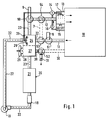
- in schematischer Darstellung eine erfindungsgemäße Einrichtung zum Kühlen einer Kabine,
- Fig. 2
- in schematischer Darstellung eine Einrichtung gemäß Fig. 1 zum Heizen einer Kabine,
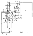
- Fig. 3
- in schematischer Darstellung ein weiteres Ausführungsbeispiel einer erfindungsgemäßen Einrichtung zum Heizen einer Kabine,
- Fig. 4
- in schematischer Darstellung die Einrichtung nach Fig. 1 im Betriebszustand Desorbieren,
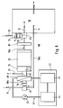
- Fig. 5
- ein weiteres Ausführungsbeispiel einer erfindungsgemäßen Einrichtung zum Heizen einer Kabine,
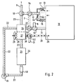
- Fig. 6
- in schematischer Darstellung eine Einrichtung zum Heizen einer Kabine eines Elektrofahrzeuges.
- Fig. 1
- a schematic representation of a device according to the invention for cooling a cabin,
- Fig. 2
- 1 schematically shows a device according to FIG. 1 for heating a cabin,
- Fig. 3
- another embodiment of a device according to the invention for heating a cabin,
- Fig. 4
- 1 in the operating state desorbing,
- Fig. 5
- another embodiment of a device according to the invention for heating a cabin,
- Fig. 6
- in a schematic representation of a device for heating a cabin of an electric vehicle.
Die in den Fig. 1 bis 4 schematisch dargestellte Einrichtung zum Heizen und/oder Kühlen einer Kabine 10, insbesondere des Fahrgastraums eines Kraftfahrzeugs, weist als Energiespeicher (Wärmequelle) einen Sorptionsreaktor 20 mit einem Sorbens, wie Zeolith oder dgl., auf sowie Luftkanälen, durch die entsprechend dem Betriebszustand mittels Luftstromsteuerelementen Luftströme geführt sind.The device for heating and / or cooling a
Der Reaktionskammer 21 des Sorptionsreaktors 20 ist über einen Zuströmkanal 22 ein Kabinenluftstrom zugeführt, der im Kühlbetrieb über einen Abluftkanal 11 und im Heizbetrieb über einen Verdunster 13, den Zuluftkanal 12, das Luftstromsteuerelement 54, den Luftkanal 7 und das Luststromsteuerelement 53 abgesaugt wird. Der Abluftkanal 11 ist mit dem Zuströmkanal 22 über ein Luftstromsteuerelement 51 verbunden, welches in der Stellung 1 eine Strömungsverbindung zwischen dem Zuströmkanal und dem Abluftkanal herstellt und in einer Stellung 2 den Abluftkanal 11 verschließt und den Zuströmkanal 22 mit einem Frischluftkanal 8 verbindet.The
Der einen trockenen Warmluftstrom führende Abströmkanal 23 der Reaktionskammer 21 ist im Kühlbetrieb über ein Luftstromsteuerelement 50 mit einem Zuluftkanal 12 der Kabine 10 verbunden. In der Stellung 1 tritt der Warmluftstrom aus dem Abströmkanal 23 in den Zuluftkanal 12, während in der Stellung 2 des Luftstromsteuerelementes 50 der Zuluftkanal 12 verschlossen ist und der Abströmkanal 23 in einen Fortluftkanal 9 mündet.The
Im Zuluftkanal 12 ist - bevorzugt unmittelbar benachbart zur Kabine 10 - ein Verdunster 13 angeordnet. Aus einem Wasserspeicher 15 wird mittels einer Pumpe 16 über ein Ventil 14 Wasser geeigneten Oberflächen 17 zur Verdunstung zugeführt.An
Der Abströmkanal 23 und der Zuströmkanal 22 stehen in wärmeübertragender Verbindung. Hierzu ist ein Wärmetauscher 24, vorzugsweise ein Kreuzstromwärmetauscher, angeordnet. Vorteilhaft ist im Zuströmkanal 22 ein weiterer Verdunster 25 mit geeigneten Oberflächen 26 angeordnet.The
Zwischen dem Sorptionsreaktor 20 und dem Kreuzstromwärmetauscher 24 ist ein wärmeabführender Wärmetauscher 27 angeordnet, der mit dem Wärmetauscher 24 eine Baueinheit bilden kann. Der Wärmetauscher 27 ist von einem Kühlluftstrom 28 durchströmt, welcher von einem Kühlgebläse 29 erzeugt ist. Der aus dem Wärmetauscher 27 austretende Kühlluftstrom ist über einen Kühlluftkanal 30 und einen Fortluftkanal 31 in die Atmosphäre abgeführt.A heat-dissipating
Zur Kühlung der Kabine wird über den Abluftkanal 11 Kabinenluft abgezogen, welche als Fortluftstrom den Wärmetauscher 24 durchströmt und erwärmt wird. Der Abluftstrom tritt über den Zuströmkanal 22 in den Sorptionsreaktor 20 ein. Das Sorbens, im gezeigten Ausführungsbeispiel Zeolith, adsorbiert die Feuchte, wobei Adsorptionswärme entsteht, die zur Aufheizung der durchströmten Luft führt. Die aus dem Abströmkanal 23 austretende Luft ist somit ein trockener Warmluftstrom, der im Wärmetauscher 27 durch den Kühlluftstrom 28 abgekühlt wird und im Wärmetauscher 24 die Restwärme zur Aufheizung der aus der Kabine abgezogenen Abluft abgibt. Über das Steuerelement 50 strömt die abgekühlte, getrocknete Luft in den Zuluftkanal 12 und den Verdunster 13, wo sie unter Verdunsten von Wasser bis zur Kühlgrenze adiabatisch abgekühlt wird. Die abgekühlte Luft tritt aus dem Verdunster vorzugsweise unmittelbar in die Kabine ein. Durch Trocknung im Sorptionsreaktor, Vorkühlung in den Wärmetauschern und adiabatische Wiederbefeuchtung der Luft kann so die Kabine gekühlt werden.To cool the cabin, cabin air is drawn off via the
Die Luftströmung von der Kabine zum Sorptionsreaktor 20 und zurück zur Kabine wird mittels eines Gebläses 19 aufrechterhalten, welches im Zuströmkanal 22 angeordnet ist. Im Zuströmkanal 22 ist vor Eintritt in die Reaktionskammer 21 ferner eine Heizvorrichtung 18 angeordnet, deren Funktionsweise nachfolgend noch beschrieben wird.The air flow from the cabin to the
Soll die Einrichtung gemäß Fig. 1 nicht nur zum Kühlen einer Kabine 10 verwendet werden, sind gemäß dem gezeigten Ausführungsbeispiel die strichliert gezeichneten Kanäle anzuordnen. Ein Brückenkanal 7 verbindet über Luftstromsteuerelemente 53 und 54 den Zuströmkanal 22 mit dem Zuluftkanal 12. Der Kühlluftkanal 30 ist in die Kabine 10 mündend ausgebildet, wobei der Fortluftkanal 31 über ein Luftstromsteuerelement 52 angeschlossen ist.If the device according to FIG. 1 is not only to be used for cooling a
Zum Heizen der Kabine 10 werden gemäß Fig. 2 die Luftstromsteuerelemente 50, 52, 53 und 54 in Stellung 2 umgeschaltet, so daß deren Klappen den Brückenkanal 7 bzw. den Kühlluftkanal 30 öffnen.2, the air
In diesem Fall wird über den Zuluftkanal 12 aus der Kabine 10 warme Abluft angesaugt, die vorzugsweise im Verdunster 13 bis zur Sättigung Wasser aufnimmt. Über den Zuluftkanal 12 und das Steuerelement 54 tritt die Fortluft über den Brückenkanal 7 und das Steuerelement 53 in den Zuströmkanal 22 ein und durchströmt - wie in Fig. 1 beschrieben - die Reaktionskammer 21 des Sorptionsreaktors 20. Die über den Abströmkanal 23 austretende Warmluft gibt ihre Wärme im Wärmetauscher 27 an den Kühlluftstrom 28 ab, der vom Kühlgebläse 29 erzeugt ist. Der Kühlluftstrom setzt sich aus Frischluft und Umluft zusammen, wobei die Umluft über das Luftstromsteuerelement 60 und den Luftkanal 32 aus der Kabine mittels Gebläse 29 abgesaugt wird. Der Kühlluftstrom 28 tritt als Heizluft über den Kühlluftkanal 30 in die Kabine 10 ein. Die abgekühlte Luft tritt über den Fortluftkanal 9 in die Atmosphäre aus.In this case, warm exhaust air is drawn in from the
Alternativ kann die Einrichtung auch zum Heizen gemäß der Darstellung in Fig. 3 benutzt werden. Über den Frischluftkanal 8 und das in Stellung 2 stehende Luftstromsteuerelement 51 wird Frischluft dem Zuströmkanal 22 zugeführt. Diese Frischluft wird im Kreuzstromwärmetauscher 24 angewärmt und über den Verdunster 25 bis zur Sättigung befeuchtet. Die angewärmte, befeuchtete Frischluft strömt in die Reaktionskammer 21 des Sorptionsreaktors 20 ein und tritt als trockener Warmluftstrom durch den Abströmkanal 23 aus, der über das in Stellung 2 stehende Luftstromsteuerelement 50 mit dem Fortluftkanal 9 verbunden ist. Über den Wärmetauscher 27 wird die aus dem Sorptionsreaktor 20 abgeführte Adsorptionswärme an den Kühlluftstrom 28 abgegeben, welcher als Heizluft über den Kühlluftkanal 30 in die Kabine 10 eintritt.Alternatively, the device can also be used for heating as shown in FIG. 3. Fresh air is supplied to the
Das Kühlgebläse 29 saugt über einen Umluftkanal 32 Kabinenluft an, wobei über ein Regelorgan 60 aus einem Frischluftkanal 33 gleichzeitig Frischluft angesaugt wird. Je nach den Betriebsbedingungen kann der angesaugten Kabinenluft ein entsprechender Anteil Frischluft zugeführt werden, wobei dieser Mischluftstrom als Kühlluftstrom den Wärmetauscher 27 durchströmt und als Heizluft in die Kabine 10 eintritt.The cooling
Bei der Ausführung gemäß Fit. 3 kann der in den Fig. 1 und 2 strichliert dargestellte Brückenkanal 7 entfallen.In the execution according to Fit. 3, the
Hat der Sorptionsreaktor eine bestimmte Wassermenge aufgenommen, muß zur Regeneration desorbiert werden. Hierzu wird, wie in Fig. 4 dargestellt, über den Frischluftkanal 8 dem Zuströmkanal 22 Frischluft zugeführt, welche vor Eintritt in die Reaktionskammer 21 in der Heizvorrichtung 18 aufgeheizt wird. Als Heizvorrichtung 18 kann ein elektrisches Heizregister verwendet werden, welches zum Beispiel beim Aufladen der Akkumulatoren eines Elektrofahrzeugs in Betrieb ist; bei einem Fahrzeug mit Verbrennungsmotor kann die notwendige Wärmeenergie dem Abgas über einen Wärmetauscher entnommen werden. Die aufgeheizte Frischluft nimmt Wasser aus dem Sorbens auf und führt dieses über den Abströmkanal 23 und den Wärmetauscher 24 sowie den Fortluftkanal 9 ab. Im Wärmetauscher 24 gibt die feuchte, warme Luft aus dem Sorptionsreaktor Wärme an die Frischluft ab, wodurch ein Teil der Abwärme zurückgewonnen wird. Das Ende des Desorptionsvorgangs kann anhand eines Anstiegs der Temperatur im Abströmkanal 23 festgestellt werden. Vorteilhaft kann der Temperaturanstieg am Ende des Desorptionsvorgangs zum Heizen der Kabine 10 ausgenutzt werden, wozu das Kühlgebläse 29 einzuschalten ist und der Kühlluftstrom als Heizluft über den Kühlluftkanal 30 der Kabine zugeführt werden kann.If the sorption reactor has absorbed a certain amount of water, it must be desorbed for regeneration. For this purpose, as shown in FIG. 4, fresh air is supplied to the
Das Ausführungsbeispiel der erfindungsgemäßen Einrichtung gemäß Fig. 5 dient ausschließlich der Heizung einer Kabine 10, z.B. des Fahrgastraums eines Elektrofahrzeugs. Hierbei wird in einem Luftstromsteuerelement 35 über den Abluftkanal 11 Abluft und über den Kanal 36 Frischluft angesaugt und über den Zuluftkanal 12 in die Kabine 10 geblasen. Ein dem Frischluftanteil entsprechender Fortluftanteil wird über den Fortluftstutzen 37 an die Umgebung abgegeben. Ein im Zuluftkanal 12 angeordnetes Gebläse 6 stellt eine ausreichende Luftumwälzung sicher.The embodiment of the device according to the invention shown in FIG. 5 is used exclusively for heating a
Wie bereits zu den vorhergehenden Ausführungsbeispielen nach den Fig. 1 bis 4 beschrieben, ist im Zuluftkanal 12 ein Wärmetauscher 27, vorzugsweise ein Kreuzstromwärmetauscher, angeordnet, durch den die trockene Warmluft geführt ist und die aufgenommene Adsorptionswärme an den Umluftstrom abgibt.As already described for the previous exemplary embodiments according to FIGS. 1 to 4, a
Der Zuströmkanal 22 zur Reaktionskammer 21 des Sorptionsreaktors 20 ist über einen Umluftkanal 38 mit dem Abströmkanal 23 verbunden. Die Luftzirkulation in dem so gebildeten, geschlossenen Kreislauf wird durch das Gebläse 19 aufrechterhalten. Die trockene, durch die Wärmeabgabe im Wärmetauscher 27 abgekühlte Umluft des Sorptionsreaktors wird vor Wiedereintritt in die Reaktionskammer 21 in dem Verdunster 25 bis zur Sättigungsgrenze befeuchtet. Der Verdunster weist einen von einer Pumpe 25a betriebenen Wasserkreislauf auf, der permanent aus einem Wasserreservoir 25b Wasser auf geeignete Oberflächen 26 zur Verdunstung aufbringt. Vorteilhaft ist im Verdunster 25 ein Wärmetauscher 40 eines Kühlkreislaufs 41 integriert, der eventuell vorhandene Abwärme aus beliebigen Aggregaten abführt. Die wärmeaufnehmende Seite des durch die Pumpe 43 betriebenen Kühlkreislaufs ist durch einen Kreis 42 stilisiert dargestellt.The
Über das Luftstromsteuerelement 50 ist der Abströmkanal 23 wahlweise mit dem Fortluftkanal 9 oder dem Umluftkanal 38 verbindbar, während über das im Gebläse integrierte Luftstromsteuerelement 51 der Frischluftkanal 8 oder der Umluftkanal 38 wahlweise mit dem Zuströmkanal 22 verbindbar ist.The
Ist eine Heizung der Kabine 10 nicht notwendig, muß dennoch die aufgenommene Wärme des Kühlkreislaufs 41 abgeführt werden. In der Klappenstellung 2 des Luftstromsteuerelementes 51 saugt das Gebläse 19 Frischluft über den Frischluftkanal 8 an, welche über einen Fortluftkanal 31 abgeblasen werden kann, der über das in Stellung 1 liegende Luftstromsteuerelement 52 zwischen dem Verdunster 25 und dem Sorptionsreaktor 20 abzweigt.If heating of the
Muß der wärmespeichernde Sorptionsreaktor 20 desorbiert werden, kann dies - wie zu Fig. 4 beschrieben - durch Öffnen des Frischluftkanals sowie des Fortluftkanals unter Hinzufügung von Wärmeenergie erfolgen. Vorzugsweise ist vorgesehen, zwischen dem Zuströmkanal 22 und dem Umluftkanal 38 ein das Gebläse 19 umgehenden Bypasskanal 39 anzuordnen, der über Luftstromsteuerelemente 55 und 56 an die genannten Kanäle anschließt. In der Stellung 1 der Luftstromsteuerelemente 55 und 56 ist der Bypasskanal 39 geschlossen; in der Stellung 2 der Luftstromsteuerelemente 51, 55 und 56 wird aus dem Frischluftkanal 8 Luft angesaugt und über den Bypasskanal 39 unmittelbar vom Gebläse 19 in den Umluftkanal 38 gespeist, so daß unter Umkehrung der bisherigen Strömungsrichtung die unter Zuführung der Wärmeenergie Q aufgeheizte Frischluft über den Abströmkanal 23 in die Reaktionskammer 21 einströmt. Zur Abfuhr dieser Wasser austragenden Luft muß am Zuströmkanal 22 ein Fortluftstutzen 9' angeordnet werden, dessen Luftstromsteuerelement 57 in Stellung 2 ein Abströmen der zugeführten Frischluft in der Desorptionsphase gewährleistet.If the heat-storing
Mit der Heizeinrichtung gemäß Fig. 5 ist auch bei einem Elektrofahrzeug, einem Hybridfahrzeug oder einem anderen ohne Verbrennungsmotor ausgeführten Fahrzeug wie auch im Falle einer Standklimatisierung über einen begrenzten Zeitraum eine ausreichende Heizung des Fahrgastraumes möglich. Die bei einem verbrennungsmotorlosen Fahrzeug abzuführenden geringen Wärmemengen können vorteilhaft zur Anreicherung der dem Sorptionsreaktor 20 zugeführten Reaktionsluft mit Wasser ausgenutzt werden.With the heating device according to FIG. 5, an adequate heating of the passenger compartment is also possible in the case of an electric vehicle, a hybrid vehicle or another vehicle without an internal combustion engine, as well as in the case of stationary air conditioning. The small amounts of heat to be dissipated in a vehicle without an internal combustion engine can advantageously be used to enrich the reaction air supplied to the
Die in Fig. 6 gezeigte Einrichtung dient insbesondere zum Heizen der Kabine 10 bzw. eines Fahrgastraumes eines Elektrofahrzeuges. An die Kabine 10 sind ein Zuluftkanal 12 und ein Abluftkanal 11 angeschlossen. Der Abluftkanal 11 ist über einen Luftführungskanal 90 mit dem Zuluftkanal 12 verbunden; der Luftführungskanal 90 weist im wesentlichen drei Abschnitte 90a, 90b, 90c auf. Der erste Abschnitt 90a des Luftführungskanals 90 erstreckt sich vom Abluftkanal 11 bis zu einem ersten Luftstromsteuerelement 51. Der zweite Abschnitt 90b des Luftführungskanals 90 beginnt bei dem ersten Luftstromsteuerelement 51 und erstreckt sich bis zu einem zweiten Luftstromsteuerelement 52, wobei in diesem zweiten Abschnitt 90b ein Gebläse 19 und ein Kühler 40 zur Kühlung des elektrischen Antriebsaggregates 44 angeordnet sind.The device shown in FIG. 6 is used in particular for heating the
Von dem zweiten Luftstromsteuerelement 52 erstreckt sich der dritte Abschnitt 90c des Luftführungskanals 90 bis zu dem Zuluftkanal 12 am Fahrgastraum 10. In dem dritten Abschnitt 90c des Luftführungskanals 90 sind in Reihe hintereinander ein Befeuchter 25, ein als Zeolith-Speicher ausgeführter Sorptions-Reaktor 20 und eine elektrische Zusatzheizung 81 angeordnet. Ohne Wärmerückgewinnung aus der Fortluft ist aus energetischen Gründen ein hoher Umluftanteil erforderlich. Durch die Verdunstung von Feuchtigkeit der Kabineninsassen nimmt die relative Feuchte in dem Fahrgastraum bei hohem Umluftanteil zu. Zur Realisierung eines hohen Umluftanteils ist daher eine Trockungseinrichtung notwendig. In dem Sorptions-Reaktor 20 wird durch das darin enthaltene Zeolith das Wasser des Luftstroms adsorbiert, wodurch dieser getrocknet wird. Die dabei freiwerdende Wärme heizt den Luftstrom weiter auf. Der Sorptions-Reaktor 20 dient somit auch als Wärmespeicher. Bei zu geringer Feuchte des Luftstroms wird diese im Befeuchter 25 erhöht, um dann in höherem Maße Wärme aus dem Sorbens, vorteilhaft Zeolithe, freisetzen zu können. In die Luftmischkammer 82 mündet ein Kaltluft führender Frischluftkanal 36, wobei der Anteil von Kalt- bzw. Frischluft dem im Abschnitt 90c geführten Luftstrom beigemischt wird. Zur Bereitstellung der erforderlichen Frischluft- bzw. Kaltluftmenge ist in dem Frischluftkanal 36 ein Gebläse 6 vorgesehen. Zur Abkühlung der Frischluft ist in dem Frischluftkanal 36 ein Verdunstungskühler 13 angeordnet.The
Der vom Luftstrom im zweiten Abschnitt 90b des Luftführungskanals 90 durchströmte Kühler 40 wird auf der anderen Seite der Wärmetauschwände vom Kühlmittel eines Kühlkreislaufs 41 für das Antriebsaggregat 44 des Elektrofahrzeugs beaufschlagt. Dabei dient das Kühlmittel des Kühlkreislaufs 41 nicht nur zur Kühlung des Antriebsmotors selbst, sondern unter Antrieb sei hier die Gesamtanordnung aus Motor, Getriebe, Leistungssteuerung und Batterieeinheit zu verstehen. In dem Kühlkreislauf 41 befindet sich eine Kühlmittelpumpe 43 zur Bewegung des Kühlmittels. Wegen auftretender Schwankungen der Wärmeentwicklung in den Komponenten des Antriebs 44 ist ein puffernder Wärmespeicher 45 vorgesehen, der vorzugsweise als Latentwärmespeicher ausgebildet ist. Durch den Wärmespeicher 45 werden die Temperaturschwankungen gedämpft, wodurch die dem Kühler 40 zugeführte Wärme auf einem innerhalb bestimmter Grenzen relativ konstant gehaltenen Niveau bleibt.The cooler 40 through which the air flow flows in the
Der Heizbetrieb für den Fahrgastraum ist von mehreren Einflüssen abhängig, vorrangig jedoch von den Umgebungstemperaturen, von der Sonneneinstrahlung und von der Innenraumtemperatur im Fahrgastraum. Daher ist die Funktion "Heizen" und die benötigte Wärmemenge bedarfsabhängig einzustellen, wohingegen die Kühlung des Antriebs im Fahrbetrieb des Elektrofahrzeugs stets benötigt wird, wenn auch der Kühlleistungsbedarf gewissen Schwankungen unterworfen ist, die beispielsweise klimatisch oder durch das Leistungsprofil bestimmt sind.The heating mode for the passenger compartment is dependent on several influences, but primarily on the ambient temperatures, the sunshine and the interior temperature in the passenger compartment. Therefore, the "heating" function and the amount of heat required must be set as required, whereas the cooling of the drive when the electric vehicle is in operation is always required, even if the cooling power requirement is subject to certain fluctuations, which are determined, for example, by climatic conditions or by the power profile.
Die Kühlung des Antriebs erfolgt dadurch, daß das Kühlmittel durch entsprechende Kühlkanäle des Motors, des Getriebes, der Batterie (ggf. mit einem Zwischenwärmeträgerkreislauf) und der Leistungssteuerung fließt, wobei das Kühlmittel im Kühlkreislauf 41 mit Hilfe der Kühlmittelpumpe 43 bewegt wird. Die Wärmeerzeugung und die somit abzuführende Wärmemenge unterliegen extremen Schwankungen, insbesondere bei Lastwechseln wie beim Beschleunigen, Abbremsen usw. Damit der Kühler 40 bezüglich seiner Abmessungen nicht unnötig groß ausgeführt werden muß, besitzt der Wärmespeicher 45 die Funktion eines thermischen Puffers, der in der Lage ist, die häufig nur kurzzeitig auftretenden Wärmemengen aufzunehmen und das Kühlmittel mit einem relativ konstanten Temperaturniveau dem Kühler 40 zuzuführen. Die im Kühlmittel enthaltene Wärme wird in dem Kühler 40 an die durch den zweiten Abschnitt 90b des Luftführungskanals 90 strömende Luft abgegeben.The drive is cooled in that the coolant flows through corresponding cooling channels of the engine, the transmission, the battery (possibly with an intermediate heat transfer circuit) and the power control, the coolant in the
Wird das Fahrzeug bei Außentemperaturen betrieben, die eine Heizung des Fahrgastraums 10 nicht erforderlich machen, so wird der zur Wärmeaufnahme im Kühler 40 erforderliche Luftstrom, der durch das Gebläse 19 erzeugt wird, mindestens annähernd vollständig durch den Frischluftkanal 8 angesaugt und durch den Kühler zu dem zweiten Luftstromsteuerelement 52 geblasen. Wenn kein Heizungsbedarf für den Fahrgastraum 10 besteht, befindet sich das zweite Luftstromsteuerelement 52 in einer Stellung, die das gesamte durch den Kühler 40 geblasene Luftvolumen durch den Fortluftkanal 31 ins Freie ableitet.If the vehicle is operated at outside temperatures that do not require heating of the
Wegen des von den Fahrzeuginsassen benötigten Sauerstoffs muß ein gewisses Luftvolumen im Fahrgastraum ständig erneuert werden. Zu diesem Zweck erzeugt das Gebläse 6 einen Luftstrom in dem Frischluftkanal 36, wobei, je nach Bedarf, die Temperatur der Frischluft in dem Verdunstungskühler 13 abgesenkt werden kann. Diese kalte Luft wird dann durch die Luftmischkammer 82 und den Zuluftkanal 12 in den Fahrgastraum 10 geleitet. Das gleiche Luftvolumen wird an anderer Stelle aus dem Fahrgastraum 10 abgezogen und - über den Fortluftkanal 31 - an die Umgebung abgegeben.Because of the oxygen required by the vehicle occupants, a certain volume of air in the passenger compartment must be constantly renewed. For this purpose, the
Besteht ein Heizungsbedarf für den Fahrgastraum 10, so wird das zweite Luftstromsteuerelement 52 verstellt, wodurch durch den Kühler 40 geleitete und erwärmte Luft teilweise oder vollständig durch den dritten Abschnitt 90c des Luftführungskanals 90 und den Sorptions-Reaktor 20 über den Zuluftkanal 12 in den Fahrgastraum 10 geleitet wird.If there is a heating requirement for the
Zusätzlich zu der Aufheizung des Luftstroms im Kühler 40 wird noch im Sorptions-Reaktor 20 die im Zeolith enthaltene Wärmeenergie an den Heizluftstrom abgegeben. Bei noch höherem Heizungsbedarf kann das Temperaturniveau zusätzlich durch die elektrische Zusatzheizung 81 weiter angehoben werden, wovon jedoch nur in Ausnahmefällen Gebrauch gemacht werden sollte, da die hierzu benötigte elektrische Energie in der Regel aus der Batterieeinheit des Elektrofahrzeuges entnommen wird.In addition to the heating of the air flow in the cooler 40, the thermal energy contained in the zeolite is also released to the heating air flow in the
Einen großen Vorteil bietet die elektrische Zusatzheizung 81 während der Dauer der Aufladung der Batterieeinheit. Mit dem Ladestrom für die Batterieeinheit kann auch ein entsprechender Strom für die elektrische Zusatzheizung 81 zugeführt werden. Mit dem Einschalten der elektrischen Zusatzheizung 81 wird vorteilhaft mindestens eines der Gebläse 6 oder 19 in Betrieb gesetzt und die Luft im Luftführungskanal 90 bewegt. Ein Luftvolumen, das der durch den Zuluftkanal 12 in den Fahrgastraum 10 eingeblasenen Heizluft entspricht, wird durch den Abluftkanal 3 aus der Kabine abgesaugt und durch den ersten und zweiten Abschnitt 90a und 90b des Luftführungskanals 90 der elektrischen Zusatzheizung 81 erneut zugeführt und weiter aufgeheizt.The electric
Wird das Luftstromsteuerelement in der Luftmischkammer 82 so eingestellt, daß die über den Frischluftkanal 36 zuströmende Kaltluft in den Abschnitt 90c des Luftfführungskanals 90 eintritt und zum Sorptions-Reaktor 20 strömt, so wird über die elektrische Zusatzheizung 81 der Luftstrom aufgeheizt und dient der Desorption des Sorbens im Reaktor 20. Der aus dem Reaktor 20 austretende feuchte Luftstrom wird über das Luftstromsteuerelement 52 und den Fortluftkanal 31 abgeleitet.If the air flow control element in the
In den gezeigten Ausführungsbeispielen sind die Luftstromsteuerelemente in sperrender Stellung oder Durchgangsstellung dargestellt. Je nach gewünschter Temperatur des Kühlluftstromes und der Heizungsluft ist eine Regelung durch eine Vielzahl von Zwischenstellungen dieser Luftstromsteuerelemente möglich.In the exemplary embodiments shown, the airflow control elements are shown in the blocking position or in the through position. Depending on the desired temperature of the cooling air flow and the heating air, regulation by a large number of intermediate positions of these air flow control elements is possible.
Claims (21)
dadurch gekennzeichnet, daß die Wärmequelle ein Sorptionsreaktor (20) mit einem Sorbens wie Zeolith oder dgl. ist, dessen Reaktionskammer (21) vom Luftstrom durchströmt ist und dabei der Luft Feuchtigkeit entzieht und die Adsorptionswärme an den Luftstrom abgibt, wobei die Reaktionskammer (21) einen Zuströmkanal (22) und einen Abströmkanal (23) aufweist und über ein Luftstromsteuerelement (51) mit einem Frischluft zuführenden Frischluftkanal (8) und stromauf über ein weiteres Luftstromsteuerelement mit einem in die Atmosphäre mündenden Fortluftkanal (9) verbindbar ist.Device for heating and / or cooling a cabin (10), in particular a passenger compartment in a motor vehicle, each with a supply air duct (12) and an exhaust duct (11) connected to the cabin (10) and a heat source, the heat energy of which can be transferred to an air stream is
characterized in that the heat source is a sorption reactor (20) with a sorbent such as zeolite or the like. The reaction chamber (21) is flowed through by the air stream and thereby removes moisture from the air and releases the heat of adsorption to the air stream, the reaction chamber (21) has an inflow duct (22) and an outflow duct (23) and can be connected via an air flow control element (51) to a fresh air duct (8) supplying fresh air and upstream via a further air flow control element to an exhaust air duct (9) opening into the atmosphere.
dadurch gekennzeichnet, daß der Abströmkanal (23) über das Luftstromsteuerelement (50) wahlweise mit dem Zuluftkanal (12) oder dem Fortluftkanal (9) verbindbar ist.Device according to claim 1,
characterized in that the outflow duct (23) can optionally be connected to the supply air duct (12) or the exhaust air duct (9) via the air flow control element (50).
dadurch gekennzeichnet, daß im Zuluftkanal (12) ein Verdunster (13) angeordnet ist.Device according to claim 1 or 2,
characterized in that an evaporator (13) is arranged in the supply air duct (12).
dadurch gekennzeichnet, daß der Zuströmkanal (22) über ein Luftstromsteuerelement (51) wahlweise mit dem Abluftkanal (11) oder dem Frischluftkanal (8) verbindbar ist.Device according to one of claims 1 to 3,
characterized in that the inflow duct (22) can optionally be connected to the exhaust air duct (11) or the fresh air duct (8) via an air flow control element (51).
dadurch gekennzeichnet, daß der Abströmkanal (23) und der Zuströmkanal (22) über einen Wärmetauscher (24), insbesondere Kreuzstromwärmetauscher, in wärmeaustauschender Verbindung stehen.Device according to one of claims 1 to 4,
characterized in that the outflow duct (23) and the inflow duct (22) are in heat-exchanging connection via a heat exchanger (24), in particular a cross-flow heat exchanger.
dadurch gekennzeichnet, daß im Abströmkanal (23) ein Wärmetauscher (27) angeordnet ist, der von einem Kühlluftstrom durchströmt ist, wobei der Kühlluftstrom vorteilhaft als Heizluftstrom der Kabine (10) zugeführt ist.Device according to one of claims 1 to 5,
characterized in that a heat exchanger (27) through which a cooling air flow flows is arranged in the outflow channel (23), the cooling air flow advantageously being supplied to the cabin (10) as a heating air flow.
dadurch gekennzeichnet, daß stromauf der Reaktionskammer (21) im Zuströmkanal (22) ein den Luftstrom befeuchtender Verdunster (25) angeordnet ist, der vorzugsweise ein regelbares Wasserzulaufventil aufweist.Device according to one of claims 1 to 6,
characterized in that upstream of the reaction chamber (21) in the inflow channel (22) there is an evaporator (25) which humidifies the air flow and which preferably has a controllable water inlet valve.
dadurch gekennzeichnet, daß im Zuströmkanal (22) vor Eintritt in die Reaktionskammer (21) eine Heizvorrichtung (18) wie ein elektrisches Heizregister oder ein von einem Heizluftstrom durchströmter Wärmetauscher angeordnet ist, wobei der Heizluftstrom vorteilhaft ein Abwärmeluftstrom ist.Device according to one of claims 1 to 7,
characterized in that in the inflow channel (22) in front Entry into the reaction chamber (21) is arranged a heating device (18) such as an electric heating register or a heat exchanger through which a heating air flow flows, the heating air flow advantageously being a waste air flow.
dadurch gekennzeichnet, daß der Abströmkanal (23) über ein Luftstromsteuerelement (50) wahlweise mit einem Umluftkanal (38) oder dem Fortluftkanal (9) und der Zuströmkanal (22) wahlweise mit dem Umluftkanal (38) oder dem Frischluftkanal (8) verbindbar ist.Device according to one of claims 1 to 8,
characterized in that the outflow duct (23) can be connected via an air flow control element (50) either to a recirculation duct (38) or the exhaust air duct (9) and the inflow duct (22) can optionally be connected to the recirculation duct (38) or the fresh air duct (8).
dadurch gekennzeichnet, daß der Zuluftkanal (12) über einen Luftführungskanal ((90) mit dem Abluftkanal (11) verbunden ist, daß in dem Luftführungskanal (90) mindestens ein Gebläse (19) zur Erzeugung einer angemessenen Luftströmung und als Wärmequelle ein in einem Kühlkreislauf (41) der Antriebskomponenten (44) befindlicher und von dessen Kühlmittel beaufschlagter Kühler (40) vorgesehen sind, und daß das Gebläse (19) und der Kühler (40) hintereinander in dem Luftführungskanal (90) angeordnet sind, wobei strömungsmäßig vor dem Kühler (40) ein erstes Luftstromsteuerelement (51), das den Anteil von Umluft und Fortluft steuert und strömungsmäßig nach dem Kühler (40), ein zweites Luftstromsteuerelement (52), das den Anteil von in den Fahrgastraum (10) eingeleiteter Heizluft und an die Umgebung abzuführender Kühlluft steuert, angeordnet sind, und daß nach dem zweiten Luftstromsteuerelement (52) der Sorptionsreaktor (20) angeordnet ist.Device according to one of claims 1 to 9,
characterized in that the supply air duct (12) is connected to the exhaust air duct (11) via an air duct (90), in that in the air duct (90) at least one fan (19) for generating an adequate air flow and as a heat source in a cooling circuit (41) of the drive components (44) located and acted upon by its coolant cooler (40) are provided, and that the fan (19) and the cooler (40) are arranged one behind the other in the air duct (90), with the flow in front of the cooler ( 40) a first air flow control element (51) which controls the proportion of recirculated air and exhaust air and flows downstream of the cooler (40), a second air flow control element (52) which controls the proportion of heating air introduced into the passenger compartment (10) and to be discharged to the environment Cooling air controls are arranged, and that after the second air flow control element (52), the sorption reactor (20) is arranged.
dadurch gekennzeichnet, daß an den Kühlkreislauf (41) Zusatzaggregate mit Wärmeentwicklung und eine Batterieeinheit, eine elektrische Steuerungseinrichtung und ein Getriebe eines Elektrofahrzeugs angeschlossen sind und eine mittels Elektromotor angetriebene Kühlmittelpumpe vorgesehen ist, wobei vorzugsweise in den Kühlkreislauf (41) ein Wärmespeicher (45), insbesondere ein Latentwärmespeicher, eingebunden ist.Device according to one of claims 1 to 10,
characterized in that additional units with heat generation and a battery unit, an electrical control device and a transmission of an electric vehicle are connected to the cooling circuit (41) and a coolant pump driven by an electric motor is provided, preferably a heat accumulator (45) in the cooling circuit (41), in particular a latent heat storage device is integrated.
dadurch gekennzeichnet, daß der Luftführungskanal (90) mindestens drei Abschnitte (90a, 90b, 90c) umfaßt, wobei ein erster Abschnitt (90a) von dem Fahrgastraum (10) bis zu dem ersten Luftstromsteuerelement (51) führt, ein zweiter Abschnitt (90b) das erste Luftstromsteuerelement (51) mit dem zweiten Luftstromsteuerelement (52) verbindet und ein dritter Abschnitt (90c) vom zweiten Luftstromsteuerelement (52) zum Fahrgastraum (10) führt, wobei im zweiten Abschnitt (90b) der Kühler (40) und das zugeordnete Gebläse (19) angeordnet sind.Device according to claim 10 or 11,
characterized in that the air duct (90) comprises at least three sections (90a, 90b, 90c), a first section (90a) leading from the passenger compartment (10) to the first air flow control element (51), a second section (90b) connects the first airflow control element (51) to the second airflow control element (52) and a third section (90c) leads from the second airflow control element (52) to the passenger compartment (10), the radiator (40) and the associated blower in the second section (90b) (19) are arranged.
dadurch gekennzeichnet, daß in dem dritten Abschnitt (90c) unmittelbar vor dem Eintritt in den Fahrgastraum (10) eine Luftmischkammer (82) angeordnet ist, in die ein Frischluftkanal (36) mündet, und daß in der Luftmischkammer (82) ein Luftstromsteuerelement (83) angeordnet ist, das die Anteile der von dem zweiten Luftstromsteuerelement (52) kommenden und von dem Frischluftkanal (12) kommenden Luftströme beeinflußt.Device according to claim 12,
characterized in that an air mixing chamber (82) into which a fresh air duct (36) opens, is arranged in the third section (90c) immediately before entering the passenger compartment (10), and in that an air flow control element (83 ) is arranged, which influences the proportions of the air flows coming from the second air flow control element (52) and coming from the fresh air duct (12).
dadurch gekennzeichnet, daß im dritten Abschnitt (90c) eine weitere Wärmequelle, vorzugsweise eine elektrische Zusatzheizung (81) vorgesehen ist.Device according to claim 12 or 13,
characterized in that a further heat source, preferably an additional electrical heater (81), is provided in the third section (90c).
dadurch gekennzeichnet, daß die Kabinenluft über den Abluftkanal (11) abgezogen und über den Zuströmkanal (22) der Reaktionskammer (21) zugeführt wird und daß die aus dem Abströmkanal (23) austretende, entfeuchtete Luft in einem Verdunster (13) durch Verdunsten von Wasser bis zur Kühlgrenze adiabatisch abgekühlt und über den Zuluftkanal (12) unmittelbar in die Kabine (10) eingeleitet wird, wobei vorzugsweise der Abluftstrom des Abluftkanals (11) vor Eintritt in die Reaktionskammer (21) durch den aus der Reaktionskammer (21) austretenden trockenen Warmluftstrom erwärmt wird.Method for cooling a cabin with a device according to one of claims 1 to 14,
characterized in that the cabin air is drawn off via the exhaust air duct (11) and fed to the reaction chamber (21) via the inflow duct (22) and in that the dehumidified air emerging from the outflow duct (23) in an evaporator (13) by evaporation of water is cooled adiabatically to the cooling limit and is introduced directly into the cabin (10) via the supply air duct (12), the exhaust air flow of the exhaust air duct (11) preferably entering the reaction chamber (21) before entering the reaction chamber (21) by the dry hot air stream emerging from the reaction chamber (21) is heated.
dadurch gekennzeichnet, daß der Abluftstrom vor Eintritt in die Reaktionskammer (21) bis an die Sättigungsgrenze befeuchtet wird.A method according to claim 15,
characterized in that the exhaust air stream is humidified to the saturation limit before entering the reaction chamber (21).
dadurch gekennzeichnet, daß der aus der Reaktionskammer (21) austretende trockene Warmluftstrom mittels eines Kühlluftstroms (28) gekühlt wird.A method according to claim 15 or 16,
characterized in that the dry hot air stream emerging from the reaction chamber (21) is cooled by means of a cooling air stream (28).
dadurch gekennzeichnet, daß über den Zuströmkanal (22) der Reaktionskammer (21) ein feuchter Luftstrom zugeführt wird, der unter Aufnahme von Wärme im Sorptionsreaktor entfeuchtet wird und der aus dem Abströmkanal (23) austretende trockene Warmluftstrom durch einen Kühlluftstrom (28) gekühlt und der Kühlluftstrom (28) der Kabine (10) als Heizluftstrom zugeführt wird, wobei der Kühlluftstrom (28) vorzugsweise aus abgezogener Kabinenluft und einem Anteil Frischluft zusammengesetzt wird.Method for heating a cabin with a device according to one of claims 1 to 14,
characterized in that a moist air stream is fed via the inflow channel (22) to the reaction chamber (21), which is dehumidified by absorbing heat in the sorption reactor and the dry hot air stream emerging from the outflow channel (23) is cooled by a cooling air stream (28) and the Cooling air flow (28) of the cabin (10) is supplied as a heating air flow, the cooling air flow (28) preferably being composed of extracted cabin air and a portion of fresh air.
dadurch gekennzeichnet, daß über den Abluftkanal (11) abgezogene Kabinenluft als feuchter Luftstrom zugeführt wird, wobei die Kabinenluft vorzugsweise in dem Verdunster (13) insbesondere bis zur Sättigungsgrenze befeuchtet und über den Zuluftkanal (12) abgezogen wird.Method according to claim 18,
characterized in that cabin air drawn off via the exhaust air duct (11) is supplied as a moist air stream, the cabin air preferably being humidified in the evaporator (13) in particular up to the saturation limit and being drawn off via the supply air duct (12).
dadurch gekennzeichnet, daß über den Frischluftkanal (8) zugeführte Frischluft als insbesondere bis zur Sättigungsgrenze befeuchteter Luftstrom zugeführt wird.Method according to claim 18 or 19,
characterized in that fresh air supplied via the fresh air duct (8) is supplied as an air stream which is in particular humidified up to the saturation limit.
dadurch gekennzeichnet, daß zur Desorption des Sorptionsspeichers (20) die Durchströmungsrichtung der Reaktionskammer (21) umgekehrt wird.Method according to one of claims 15 to 20,
characterized in that the direction of flow through the reaction chamber (21) is reversed for desorption of the sorption accumulator (20).
Applications Claiming Priority (4)
| Application Number | Priority Date | Filing Date | Title |
|---|---|---|---|
| DE9112332 | 1991-03-19 | ||
| DE9112332U | 1991-03-19 | ||
| DE4125993A DE4125993C2 (en) | 1991-08-06 | 1991-08-06 | Device and method for cooling and / or heating a cabin |
| DE4125993 | 1991-08-06 |
Publications (3)
| Publication Number | Publication Date |
|---|---|
| EP0504643A2 true EP0504643A2 (en) | 1992-09-23 |
| EP0504643A3 EP0504643A3 (en) | 1993-11-03 |
| EP0504643B1 EP0504643B1 (en) | 1997-06-25 |
Family
ID=25906126
Family Applications (1)
| Application Number | Title | Priority Date | Filing Date |
|---|---|---|---|
| EP92103510A Expired - Lifetime EP0504643B1 (en) | 1991-03-19 | 1992-02-29 | Process and apparatus for cooling or heating a cabin |
Country Status (4)
| Country | Link |
|---|---|
| US (1) | US5388423A (en) |
| EP (1) | EP0504643B1 (en) |
| DE (1) | DE59208640D1 (en) |
| ES (1) | ES2103841T3 (en) |
Cited By (6)
| Publication number | Priority date | Publication date | Assignee | Title |
|---|---|---|---|---|
| DE4304075A1 (en) * | 1993-02-11 | 1994-08-18 | Behr Gmbh & Co | Device for reducing air humidity in a passenger compartment |
| FR2705622A1 (en) * | 1993-05-27 | 1994-12-02 | Valeo Thermique Habitacle | Method and device for heating the passenger compartment of a motor vehicle |
| FR2712849A1 (en) * | 1993-11-24 | 1995-06-02 | Valeo Thermique Habitacle | Air conditioning system for interior of electrically powered vehicle |
| US5505251A (en) * | 1992-10-26 | 1996-04-09 | Valeo Climatisation | Cooling and air conditioning apparatus for an electric vehicle |
| DE4304077C2 (en) * | 1993-02-11 | 2001-08-23 | Behr Gmbh & Co | Device for lowering the air humidity in a passenger compartment of a motor vehicle |
| DE102007055407A1 (en) * | 2007-11-19 | 2009-05-20 | Menerga Gmbh | Plant for dehumidifying the air of a swimming pool hall |
Families Citing this family (21)
| Publication number | Priority date | Publication date | Assignee | Title |
|---|---|---|---|---|
| DE4304076C2 (en) * | 1993-02-11 | 1996-03-07 | Behr Gmbh & Co | Method and device for heating the passenger compartment of a motor vehicle |
| DE4334808C1 (en) * | 1993-10-13 | 1994-10-06 | Daimler Benz Ag | Method for operating a sorption installation for air conditioning vehicles, especially electric vehicles, and a sorption installation, especially for implementing the method |
| DE4414595A1 (en) * | 1994-04-27 | 1995-11-02 | Behr Gmbh & Co | Device and method for heating a passenger compartment in a motor vehicle |
| US5873256A (en) * | 1994-07-07 | 1999-02-23 | Denniston; James G. T. | Desiccant based humidification/dehumidification system |
| WO1996006748A1 (en) * | 1994-09-01 | 1996-03-07 | Johann Himmelsbach | Motor vehicle heat exchanger |
| EP0809776A1 (en) * | 1995-02-13 | 1997-12-03 | James G. T. Denniston | Desiccant based humidification/dehumidification system |
| DE19527638A1 (en) * | 1995-07-28 | 1997-01-30 | Behr Gmbh & Co | Air drying device, in particular for motor vehicles |
| US5901572A (en) * | 1995-12-07 | 1999-05-11 | Rocky Research | Auxiliary heating and air conditioning system for a motor vehicle |
| US6029462A (en) * | 1997-09-09 | 2000-02-29 | Denniston; James G. T. | Desiccant air conditioning for a motorized vehicle |
| US6276166B1 (en) * | 1999-07-20 | 2001-08-21 | Rocky Research | Auxiliary thermal storage heating and air conditioning system for a motor vehicle |
| US7037360B2 (en) * | 2002-08-15 | 2006-05-02 | Mitsubishi Chemical Corporation | Adsorbent for heat utilization system, adsorbent for regenerator system, regenerator system comprising the adsorbent, ferroaluminophosphate and method for production thereof |
| JP4281564B2 (en) * | 2004-02-02 | 2009-06-17 | 株式会社デンソー | Air conditioner for vehicles |
| KR20070051835A (en) * | 2004-06-08 | 2007-05-18 | 나노포어 인코포레이티드 | Sorption cooling systems, their use in automotive cooling applications and methods relating to the same |
| US20090293526A1 (en) * | 2008-06-02 | 2009-12-03 | Takumi Ichinomiya | Water mist cooling system |
| CN201708684U (en) * | 2010-06-07 | 2011-01-12 | 柳州五菱汽车有限责任公司 | Heat dissipation system for driving controller of electric vehicle |
| DE102010064134A1 (en) * | 2010-12-23 | 2012-06-28 | Robert Bosch Gmbh | An air conditioning device for a vehicle and method for controlling a climate in a passenger compartment of a vehicle |
| JP5967403B2 (en) * | 2011-12-05 | 2016-08-10 | パナソニックIpマネジメント株式会社 | Air conditioner for vehicles |
| EP2631099B1 (en) * | 2012-02-23 | 2014-07-16 | Weidmann Plastics Technology AG | Motor vehicle with a water chamber and air conditioning system |
| CN104185564B (en) * | 2012-03-29 | 2018-12-04 | 飞利浦灯具控股公司 | heating device |
| AT517516B1 (en) * | 2015-08-04 | 2018-02-15 | Rep Ip Ag | Transport container for transporting temperature-sensitive cargo |
| DE102019213860A1 (en) * | 2019-09-11 | 2021-03-11 | Mahle International Gmbh | Air conditioning system for a motor vehicle |
Citations (6)
| Publication number | Priority date | Publication date | Assignee | Title |
|---|---|---|---|---|
| BE572293A (en) * | ||||
| US2344384A (en) * | 1937-01-06 | 1944-03-14 | Altenkirch Edmund | Air conditioning |
| US2730874A (en) * | 1949-10-14 | 1956-01-17 | Garrett Corp | Air conditioner employing an expansion evaporation air cycle |
| JPS5966627A (en) * | 1982-10-08 | 1984-04-16 | Hitachi Ltd | Absorption type air conditioner |
| EP0167096A2 (en) * | 1984-07-02 | 1986-01-08 | Dieter Kronauer | Air conditioning with a storage heating |
| DE3424278A1 (en) * | 1984-07-02 | 1986-01-23 | Dieter 3002 Wedemark Kronauer | Process and apparatus for the dehumidifying and heating of rooms with large open water surfaces, especially swimming pool halls |
Family Cites Families (2)
| Publication number | Priority date | Publication date | Assignee | Title |
|---|---|---|---|---|
| US2075036A (en) * | 1935-08-26 | 1937-03-30 | Henry L Hollis | Air conditioning apparatus and process |
| AU641083B2 (en) * | 1991-03-05 | 1993-09-09 | Matsushita Electric Industrial Co., Ltd. | Humidity control apparatus |
-
1992
- 1992-02-29 DE DE59208640T patent/DE59208640D1/en not_active Expired - Fee Related
- 1992-02-29 EP EP92103510A patent/EP0504643B1/en not_active Expired - Lifetime
- 1992-02-29 ES ES92103510T patent/ES2103841T3/en not_active Expired - Lifetime
- 1992-03-16 US US07/851,655 patent/US5388423A/en not_active Expired - Fee Related
Patent Citations (6)
| Publication number | Priority date | Publication date | Assignee | Title |
|---|---|---|---|---|
| BE572293A (en) * | ||||
| US2344384A (en) * | 1937-01-06 | 1944-03-14 | Altenkirch Edmund | Air conditioning |
| US2730874A (en) * | 1949-10-14 | 1956-01-17 | Garrett Corp | Air conditioner employing an expansion evaporation air cycle |
| JPS5966627A (en) * | 1982-10-08 | 1984-04-16 | Hitachi Ltd | Absorption type air conditioner |
| EP0167096A2 (en) * | 1984-07-02 | 1986-01-08 | Dieter Kronauer | Air conditioning with a storage heating |
| DE3424278A1 (en) * | 1984-07-02 | 1986-01-23 | Dieter 3002 Wedemark Kronauer | Process and apparatus for the dehumidifying and heating of rooms with large open water surfaces, especially swimming pool halls |
Non-Patent Citations (1)
| Title |
|---|
| PATENT ABSTRACTS OF JAPAN vol. 8, no. 174 (M-316)(1611) 10. August 1984 & JP-A-59 066 627 ( HITACHI ) 16. April 1984 * |
Cited By (6)
| Publication number | Priority date | Publication date | Assignee | Title |
|---|---|---|---|---|
| US5505251A (en) * | 1992-10-26 | 1996-04-09 | Valeo Climatisation | Cooling and air conditioning apparatus for an electric vehicle |
| DE4304075A1 (en) * | 1993-02-11 | 1994-08-18 | Behr Gmbh & Co | Device for reducing air humidity in a passenger compartment |
| DE4304077C2 (en) * | 1993-02-11 | 2001-08-23 | Behr Gmbh & Co | Device for lowering the air humidity in a passenger compartment of a motor vehicle |
| FR2705622A1 (en) * | 1993-05-27 | 1994-12-02 | Valeo Thermique Habitacle | Method and device for heating the passenger compartment of a motor vehicle |
| FR2712849A1 (en) * | 1993-11-24 | 1995-06-02 | Valeo Thermique Habitacle | Air conditioning system for interior of electrically powered vehicle |
| DE102007055407A1 (en) * | 2007-11-19 | 2009-05-20 | Menerga Gmbh | Plant for dehumidifying the air of a swimming pool hall |
Also Published As
| Publication number | Publication date |
|---|---|
| DE59208640D1 (en) | 1997-07-31 |
| ES2103841T3 (en) | 1997-10-01 |
| EP0504643A3 (en) | 1993-11-03 |
| EP0504643B1 (en) | 1997-06-25 |
| US5388423A (en) | 1995-02-14 |
Similar Documents
| Publication | Publication Date | Title |
|---|---|---|
| EP0504643A2 (en) | Process and apparatus for cooling or heating a cabin | |
| EP0575402B1 (en) | Process for cooling drive components and heating the passenger compartment of a motor vehicle, especially an electrically driven vehicle, and arrangement for implementing the process | |
| DE102020106948A1 (en) | Heat pump system for a vehicle | |
| DE102019125197A1 (en) | HEAT PUMP SYSTEM FOR A VEHICLE | |
| DE102019130748A1 (en) | HEAT PUMP SYSTEM FOR VEHICLE | |
| DE102019128735A1 (en) | Heat pump system for a vehicle | |
| DE102012019005B4 (en) | Thermal conditioning of a motor vehicle having an electric drive | |
| DE112019006348T5 (en) | THERMAL MANAGEMENT SYSTEM | |
| DE102021117639A1 (en) | Heat pump system for a vehicle | |
| DE102013110965A1 (en) | Air conditioning system for a motor vehicle | |
| DE102015112030A1 (en) | Modular air conditioning system of a motor vehicle | |
| DE102021117580A1 (en) | Heat pump system for a vehicle | |
| EP1350645B1 (en) | Method and apparatus for drying an evaporator in an air conditioning system | |
| DE102017116207A1 (en) | VEHICLE ASSIST HVAC SYSTEM USING A COOLANT GRINDING FOR COOLING A COMPONENT OF A VEHICLE INTERIOR | |
| DE102018211559B4 (en) | Vehicle with an air conditioning device for heating and cooling an electrical energy store | |
| DE102012009909A1 (en) | Air conditioning device for motor car, has channels connected with outside chamber at input side by independent controllable flaps, and fan devices comprising independent controllable fans to which channels are attached | |
| DE102013110562A1 (en) | Heating / cooling system for motor vehicles and method for the air conditioning of a vehicle interior | |
| DE112020003706T5 (en) | Integrated thermal management circuit for a vehicle | |
| DE9202466U1 (en) | Device for cooling drive components and for heating a passenger compartment of a motor vehicle, in particular an electric vehicle | |
| DE102017223146A1 (en) | Vehicle with a cooling module of an air conditioning device for conditioning a supply air flow supplied into a vehicle interior | |
| DE4125993C2 (en) | Device and method for cooling and / or heating a cabin | |
| DE102017010342A1 (en) | Charging station for charging an energy storage device of a motor vehicle, method for operating a charging station and method for operating a motor vehicle | |
| DE4140321A1 (en) | Electric vehicle with heat carrier circuit esp. for warming up electric drive unit - heats up supplied air flow arriving in vehicle inner space with supply air flow fed by exhaust air flow from vehicle inner space | |
| DE102017004965B4 (en) | Temperierungskreislauf for a motor vehicle, method for operating a Temperierungskreislaufs and motor vehicle | |
| DE102021200534A1 (en) | vehicle air conditioning system |
Legal Events
| Date | Code | Title | Description |
|---|---|---|---|
| PUAI | Public reference made under article 153(3) epc to a published international application that has entered the european phase |
Free format text: ORIGINAL CODE: 0009012 |
|
| AK | Designated contracting states |
Kind code of ref document: A2 Designated state(s): DE ES FR GB IT SE |
|
| PUAL | Search report despatched |
Free format text: ORIGINAL CODE: 0009013 |
|
| AK | Designated contracting states |
Kind code of ref document: A3 Designated state(s): DE ES FR GB IT SE |
|
| 17P | Request for examination filed |
Effective date: 19940423 |
|
| 17Q | First examination report despatched |
Effective date: 19950331 |
|
| GRAG | Despatch of communication of intention to grant |
Free format text: ORIGINAL CODE: EPIDOS AGRA |
|
| GRAH | Despatch of communication of intention to grant a patent |
Free format text: ORIGINAL CODE: EPIDOS IGRA |
|
| ITF | It: translation for a ep patent filed | ||
| GRAH | Despatch of communication of intention to grant a patent |
Free format text: ORIGINAL CODE: EPIDOS IGRA |
|
| GRAA | (expected) grant |
Free format text: ORIGINAL CODE: 0009210 |
|
| AK | Designated contracting states |
Kind code of ref document: B1 Designated state(s): DE ES FR GB IT SE |
|
| GBT | Gb: translation of ep patent filed (gb section 77(6)(a)/1977) |
Effective date: 19970626 |
|
| REF | Corresponds to: |
Ref document number: 59208640 Country of ref document: DE Date of ref document: 19970731 |
|
| ET | Fr: translation filed | ||
| REG | Reference to a national code |
Ref country code: ES Ref legal event code: FG2A Ref document number: 2103841 Country of ref document: ES Kind code of ref document: T3 |
|
| PLBE | No opposition filed within time limit |
Free format text: ORIGINAL CODE: 0009261 |
|
| STAA | Information on the status of an ep patent application or granted ep patent |
Free format text: STATUS: NO OPPOSITION FILED WITHIN TIME LIMIT |
|
| 26N | No opposition filed | ||
| PGFP | Annual fee paid to national office [announced via postgrant information from national office to epo] |
Ref country code: GB Payment date: 19990122 Year of fee payment: 8 |
|
| PGFP | Annual fee paid to national office [announced via postgrant information from national office to epo] |
Ref country code: ES Payment date: 19990211 Year of fee payment: 8 |
|
| PGFP | Annual fee paid to national office [announced via postgrant information from national office to epo] |
Ref country code: FR Payment date: 19990215 Year of fee payment: 8 |
|
| PGFP | Annual fee paid to national office [announced via postgrant information from national office to epo] |
Ref country code: SE Payment date: 19990222 Year of fee payment: 8 |
|
| PG25 | Lapsed in a contracting state [announced via postgrant information from national office to epo] |
Ref country code: GB Free format text: LAPSE BECAUSE OF NON-PAYMENT OF DUE FEES Effective date: 20000229 |
|
| PG25 | Lapsed in a contracting state [announced via postgrant information from national office to epo] |
Ref country code: SE Free format text: LAPSE BECAUSE OF NON-PAYMENT OF DUE FEES Effective date: 20000301 Ref country code: ES Free format text: LAPSE BECAUSE OF NON-PAYMENT OF DUE FEES Effective date: 20000301 |
|
| GBPC | Gb: european patent ceased through non-payment of renewal fee |
Effective date: 20000229 |
|
| PG25 | Lapsed in a contracting state [announced via postgrant information from national office to epo] |
Ref country code: FR Free format text: LAPSE BECAUSE OF NON-PAYMENT OF DUE FEES Effective date: 20001031 |
|
| EUG | Se: european patent has lapsed |
Ref document number: 92103510.1 |
|
| REG | Reference to a national code |
Ref country code: FR Ref legal event code: ST |
|
| REG | Reference to a national code |
Ref country code: ES Ref legal event code: FD2A Effective date: 20010910 |
|
| PGFP | Annual fee paid to national office [announced via postgrant information from national office to epo] |
Ref country code: DE Payment date: 20020315 Year of fee payment: 11 |
|
| PG25 | Lapsed in a contracting state [announced via postgrant information from national office to epo] |
Ref country code: DE Free format text: LAPSE BECAUSE OF NON-PAYMENT OF DUE FEES Effective date: 20030902 |
|
| PG25 | Lapsed in a contracting state [announced via postgrant information from national office to epo] |
Ref country code: IT Free format text: LAPSE BECAUSE OF NON-PAYMENT OF DUE FEES;WARNING: LAPSES OF ITALIAN PATENTS WITH EFFECTIVE DATE BEFORE 2007 MAY HAVE OCCURRED AT ANY TIME BEFORE 2007. THE CORRECT EFFECTIVE DATE MAY BE DIFFERENT FROM THE ONE RECORDED. Effective date: 20050228 |