EP0504009B1 - Expandable garment bag and hanger bar therefor - Google Patents
Expandable garment bag and hanger bar therefor Download PDFInfo
- Publication number
- EP0504009B1 EP0504009B1 EP92400564A EP92400564A EP0504009B1 EP 0504009 B1 EP0504009 B1 EP 0504009B1 EP 92400564 A EP92400564 A EP 92400564A EP 92400564 A EP92400564 A EP 92400564A EP 0504009 B1 EP0504009 B1 EP 0504009B1
- Authority
- EP
- European Patent Office
- Prior art keywords
- section
- bar
- cam
- telescoping
- hangers
- Prior art date
- Legal status (The legal status is an assumption and is not a legal conclusion. Google has not performed a legal analysis and makes no representation as to the accuracy of the status listed.)
- Expired - Lifetime
Links
Images

Classifications
-
- A—HUMAN NECESSITIES
- A45—HAND OR TRAVELLING ARTICLES
- A45C—PURSES; LUGGAGE; HAND CARRIED BAGS
- A45C3/00—Flexible luggage; Handbags
- A45C3/004—Foldable garment carrier bags
-
- A—HUMAN NECESSITIES
- A45—HAND OR TRAVELLING ARTICLES
- A45C—PURSES; LUGGAGE; HAND CARRIED BAGS
- A45C13/00—Details; Accessories
- A45C13/02—Interior fittings; Means, e.g. inserts, for holding and packing articles
- A45C13/03—Means for holding garments
-
- A—HUMAN NECESSITIES
- A45—HAND OR TRAVELLING ARTICLES
- A45C—PURSES; LUGGAGE; HAND CARRIED BAGS
- A45C7/00—Collapsible or extensible purses, luggage, bags or the like
- A45C7/0059—Flexible luggage; Hand bags
- A45C7/0063—Flexible luggage; Hand bags comprising an integrated expansion device
- A45C7/0068—Flexible luggage; Hand bags comprising an integrated expansion device with slide fastener strips
Definitions
- the invention relates to garment bags, and in particular, garment bags which can be altered on demand to provide greater depth to accommodate a large number of garments on hangers than would otherwise be possible. More particularly, the invention relates to hanger bar and retainer system for the garments on hangers normally suspended within the garment bag's main packing section.
- Garment bags have included a zipper track mechanism positioned in the rail or gusset portion of the garment bag which permits the garment bag to have two thicknesses or depths.
- This zipper arrangement is detailed in U.S. Patent 3,443,671, herein incorporated by reference.
- this zipper arrangement comprises a zipper track which extends beyond a full periphery of the rail portions of the garment bag to close upon itself. Between the separate zipper tracks is a fabric panel or gusset which can be folded up on action of the zipper, closing the zipper track. In this way, the rails of the garment bag can be expanded to accommodate the extra depth defined by this fabric section.
- a simple bar-like device for retaining hangers has been provided in these types of garment bags.
- the hanger bar includes one, and perhaps two, rectangular shaped loops of steel bar, the bar having a diameter of about .25".
- the loop is provided with a hinge, approximately in its middle, to permit the outer ends of the bar loop to pivot at right angles to the vertical plane.
- the non-pivoted portion of the bar is fixed to the upper rail of the garment bag.
- the hanger bar When the garment bag is in its collapsed state or, in other words, when the zipper is closed to fold up the cloth section, the hanger bar is normally folded to present a fairly short bar portion to accommodate hangers.
- the zipper track arrangement is operated to expand the cloth section. The user may pivot the outer end of the bar loop outward to present an elongated bar section for hanging a greater number of garments on hangers.
- This pivotal hanger bar arrangement is sized to accommodate primarily the pivoting-hook type hangers, sometimes called "Gooseneck" type hangers, rather than the hooked portions of ordinary closet-type hangers. If the user places a hooked portion of the hanger over such a hanger bar, there is no effective means for retaining the hooked portion in place over the hanger bar. Thus, it is likely that the hooked portion will become disengaged from the bar and the garments thereon will fall to the bottom of the garment bag causing undue wrinkling of those garments.
- U.S. Patent 4,736,854 assigned to the assignee of the present invention, shows a telescoping hanger bar which includes a spool-like member which can be extended to a situation wherein the hooked portions of hangers can be placed over the hanger bar.
- the hangers When locked in the collapsed position, the hangers are retained beneath a concave surface on the inside of the hanger bar construction.
- the telescoping hanger bar When the telescoping hanger bar is in its extended position, there is no mechanism for retaining the hooked portion of the hangers, nor is there means provided for locking the spool-like portion of the hanger bar in this extended position.
- the telescoping operation has great benefit when packing, it is relatively unusable for accommodating the greater packing capacity of garment bags of the type described above.
- the device for suspending the hangers by engaging the hooked portions includes :
- the known device is not able to accommodate a greater number of garments on hangers when the bar means is in its extended position, because of a flange provided on the second movable telescoping bar section and closely surrounded by the first surface.
- Another object of the invention is to provide a hanging device for hooked-type hangers which has two lengths, a first length accommodating at least one of such garments, and a second length accommodating a greater number of garments on hangers. In both lengths, there is provided a retaining surface positioned above the hanger bar for retaining the hooked portions in place.
- the luggage case includes a device for suspending the hangers by engaging the hooked portions thereof.
- the device for suspending includes bar mans comprising a first stationary telescoping bar section defining a first length from which at least one of said garments on hangers may be hung, and a second movable telescoping bar section defining a second length when in an extended position.
- the device for suspending further includes lock means, carried by said bar means for locking said bar means when it is in a retracted position and in said extended position, and a first surface positioned above said first stationary telescoping bar section for retaining said hooked portions on said first length.
- the extended position of said bar means allows a greater number of garments on hangers to be accommodated thereon, and the suspending device comprises a second surface positioned above said second movable telescoping bar section for retaining hooked portions on said second movable telescoping bar section.
- a luggage case includes a device for suspending such hangers by engaging the hooked portions thereof.
- This device includes a bar means over which hooked portions of hangers may be positioned.
- the bar means defines a first length from which at least one of the garments on hangers may be hung.
- a means is positioned above and at the end of the bar to retain the hooked portions on the bar means.
- the luggage case preferably has a slide type fastener and track arrangement to permit the luggage case to be selectively expanded in volume to accommodate varying numbers of garments on hangers.
- the means for retaining the hooked portion of hangers comprises an L-shaped member, one end of which is attached to the distal end of the bar and the other end extends parallel to and above the bar. This L-shaped member is positioned above the bar both when it is in its first length as well as when it is in its second length.
- the invention also concerns a device for suspending garments on hangers within a garment bag, of the type including means for fastening said device in an upper portion of said garment bag and bar means over which hooked portions of the hangers may be positioned.
- the bar means comprises a first stationary telescoping bar section fixed to said means for fastening, said first stationary telescoping bar section defining a first length from which at least one of said garments on hangers may be hung, and a second movable telescoping bar section defining a second length when in an extended position.
- the device further includes lock means, carried by said bar means for locking said bar means when it is in a retracted position and in said extended position, and a first surface positioned above said first stationary telescoping bar section for retaining said hooked portions on said first length.
- the extended position of said bar means allows a greater number of garments on hangers to be accommodated thereon, and the suspending device comprises a second surface carried by said second movable telescoping bar section for retaining hooked portions on said second movable telescoping bar section.
- the invention also comprises a device for suspending garments on hangers within a garment bag comprising means for fastening the device to the upper portion of the garment bag, and a bar over which hooked portions of the hangers may be positioned.
- a device provided for lengthening the bar beyond the first length to a second length whereby a greater number of garments may be accommodated thereon.
- means for locking the bar in either its first length or its second length.
- This means for locking preferably comprises a cam in the form of a slot on a cam follower which is carried in the slot.
- the bar comprises a first telescoping section fixed to the device, and the second telescoping section actually mounted to the first section for axial movement relative to the first telescoping section.
- the cam and the cam-follower are carried respectively by the first section and the second section.
- the suspending device includes means for retaining the hooked portions of the hangers on the bar.
- This means comprises an L-shaped member, one end of which is fastened to the second telescoping portion, and the other end extends back over the bar.
- the L-shaped retaining member is carried by the second telescoping section, and thus operates to retain hooked portions of the garments regardless of whether the bar is in its first length or has been extended to its second length.
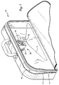
- Figure 1 shows a luggage case of a garment bag type in accordance with the instant invention.
- Figure 2 shows the hanger suspending device in a first position.
- Figure 3 shows the hanger device operated in the interim position.
- Figure 4 shows the hanger device with the hanger bar in the lengthened position.
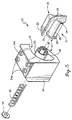
- Figure 5 is an exploded view of the suspending device in accordance with the instant invention.
- the garment bag (10) is of a generally known type and includes a zipper track and zipper slider and track arrangement (12) which extends around the entire periphery of the garment bag in the rail or gusset portion thereof.
- the slider (14) is mounted on the track arrangement to permit a cloth section (16), also extending around the full periphery of the garment bag, to either be folded up beneath the closed zipper track, or extended to in turn actually increase the width of the rail portion of the garment bag. In this way, varying amounts of garments can be packed in the garment bag. It is known that garments are retained in a relatively wrinkle-free condition if they are packed firmly, but not crushed, within a garment bag or other luggage case. Accordingly, with the help of the operation of the zipper slider (14) as outlined above, garments can be packed more easily for safe travel.
- the device (20) includes rod means (22), which is held in cantilever fashion by body portion (24).
- Body portion (24) itself provides means (24a) for suspending the device (20) from the upper portion of the garment bag (10).
- the bar means (22) as detailed below, is provided with means which lengthens the bar means from the first length, as shown in solid lines in Figure 1 (to accommodate at least one garment hanger), to a second length, as shown in phantom in Figure 1. In this second length condition, a greater number of garments on hangers can be accommodated.
- a hanger retaining means (30) is positioned so as to resist the dislodging of the hooked portion of the hangers from the hanger bar means.
- the retaining means (30) includes a concave surface (33 of Figure 4) positioned parallel to and above the hanger bar in a manner generally taught by U.S. Patent 4,736,854 referred to above.
- retaining means (30) is generally L-shaped, one portion thereof fixedly attached to the distal end of the bar means, and the other portion (32) extending back above and parallel to (22) the bar means.
- the hanger bar means (22) includes a generally round, cylindrically convex surface, at least along a majority of its outer periphery. It is joined to the body portion (24) by cantilever support (26).
- cantilever support 26
- hangers should be arranged with their hooked portions facing only in one direction since the shank portion of the hangers (that is that portion which connects the hook portion to the garment engaging portion) must hang vertically down on the side of the hanger bar means opposite from the cantilever portion (26) as illustrated in Figure 1.
- the hanger bar (22) includes a handle (28) which can be gripped easily by the user to rotate the outer portion of the hanger bar means to operate the same as will be outlined below.
- the retaining means (30) comprises an extension of the handle (28).
- the other portion (32) of the retaining means includes a concave portion (33) as shown in Figure 4. It is this surface (and the extension of the handle 28) that generally retains the hooked portions of the hangers and prevents them from dislodging during the rigors of travel.
- bosses (24a) which receive self tapping screws (not shown) passing through the upper rail of the garment bag. In this way, the entire device is firmly held in the upper portion of the garment bag.
- Figure 3 shows the device in a second operative condition.
- a first telescoping section (23) retains a second telescoping section (25) for selective movement in an axial direction as well as a relative rotational motion as will be detailed.
- hangers can be easily placed on the cylindrical surface of first section (23) by moving the hooked portions thereof axially over the front end of the rod means and placing them on section (23).
- the handle (28) can be operated to rotate the second section (25) clockwise to bring the hanger retaining means (30) to block the front of the opening as well as bring the concave surface (33) of the retainer portion (32) above the hanger to prevent the hanger from being displaced upwardly off of the section (23).
- this vertical position as shown in Figure 2 is held by a locking system and will stay in this position unless by the handle (28).
- the operator need only rotate handle (28) counter-clockwise to expose the front opening of the device and simultaneously remove the retainer means from the concave surface from above the hanger hooks.
- the telescoping section (25) together with the hanger retainer (30) attached thereto may be moved from its position shown in Figure 3 to a position in Figure 4, in the following manner. From the position shown in Figure 3, spring means (42 in Figure 5) is released to move the second telescoping section axially outward. Once in the fully lengthened condition, handle (28) is again rotated clockwise to bring the hanger retaining means (30) in its operative condition after additional portions of hangers are placed over the lengthened bar means (22).
- the bar means (22) is locked in its telescoping position and the retainer surface (33) on its retaining means (30) is held in hanger retaining position shown with the hooked portions trapped on the lengthened rod means (22) by surface (33) and the downwardly facing curved surface (21) of member (24), and the vertical leg extension of handle (28).
- a slot (31) which includes a first cam section (34) which extends substantially perpendicular to the axis of the rod means and partially circumferentially around and approximate to the distal end of second telescoping section (25).
- a second cam section (35) extends substantially parallel to the axis of the bar means and thus along an axial surface of the second telescoping section (25).
- a third cam section (36) is at the other end of second cam section (35). It also is perpendicular to the axis of the bar means.
- cam follower in the form of a pin (38). This is an ordinary steel pin pressed through a radial hole extending from the outer surface of the device (24) through the inner surface of first telescoping section (23).
- the inner telescopic section, second telescoping section (25), is mounted inside the first telescoping section (23) and positioned as shown in Figure 3. Then the cam follower pin (38) is inserted through the radial bore to bring the inner end thereof into engagement in the slot (35). Specifically, in the region of the first cam section (34).
- This cam follower pin not only controls the axial and turning motion of second telescoping section (25) it also locks the section (25) in the positions shown in Figures 2 and 4, as well as retains that section and keeps it from falling out.
- the bias spring (42) extends up an axial bore (not shown) in second telescoping section (25) and is retained in a compressed state by retaining washer (44) which engages bosses (not shown) at the rear side of the device (24).
- the cam follower pin may be carried by the second telescoping section (25) and the cam be part of the inner surface of the first telescoping section (23).
- the cam surface could be provided on the inner surface of the main body (24) of the hanger retaining device with a cam follower carried by the outer surface of the hanger retainer (30).
Landscapes
- Purses, Travelling Bags, Baskets, Or Suitcases (AREA)
- Holders For Apparel And Elements Relating To Apparel (AREA)
- Bag Frames (AREA)
- Warehouses Or Storage Devices (AREA)
- Chain Conveyers (AREA)
- Supplying Of Containers To The Packaging Station (AREA)
Abstract
Description
- The invention relates to garment bags, and in particular, garment bags which can be altered on demand to provide greater depth to accommodate a large number of garments on hangers than would otherwise be possible. More particularly, the invention relates to hanger bar and retainer system for the garments on hangers normally suspended within the garment bag's main packing section.
- Garment bags have included a zipper track mechanism positioned in the rail or gusset portion of the garment bag which permits the garment bag to have two thicknesses or depths. This zipper arrangement is detailed in U.S. Patent 3,443,671, herein incorporated by reference. In general, this zipper arrangement comprises a zipper track which extends beyond a full periphery of the rail portions of the garment bag to close upon itself. Between the separate zipper tracks is a fabric panel or gusset which can be folded up on action of the zipper, closing the zipper track. In this way, the rails of the garment bag can be expanded to accommodate the extra depth defined by this fabric section. A simple bar-like device for retaining hangers has been provided in these types of garment bags. The hanger bar includes one, and perhaps two, rectangular shaped loops of steel bar, the bar having a diameter of about .25". The loop is provided with a hinge, approximately in its middle, to permit the outer ends of the bar loop to pivot at right angles to the vertical plane. The non-pivoted portion of the bar is fixed to the upper rail of the garment bag. When the garment bag is in its collapsed state or, in other words, when the zipper is closed to fold up the cloth section, the hanger bar is normally folded to present a fairly short bar portion to accommodate hangers. When the zipper track arrangement is operated to expand the cloth section. The user may pivot the outer end of the bar loop outward to present an elongated bar section for hanging a greater number of garments on hangers. This pivotal hanger bar arrangement is sized to accommodate primarily the pivoting-hook type hangers, sometimes called "Gooseneck" type hangers, rather than the hooked portions of ordinary closet-type hangers. If the user places a hooked portion of the hanger over such a hanger bar, there is no effective means for retaining the hooked portion in place over the hanger bar. Thus, it is likely that the hooked portion will become disengaged from the bar and the garments thereon will fall to the bottom of the garment bag causing undue wrinkling of those garments.
- U.S. Patent 4,736,854, assigned to the assignee of the present invention, shows a telescoping hanger bar which includes a spool-like member which can be extended to a situation wherein the hooked portions of hangers can be placed over the hanger bar. When locked in the collapsed position, the hangers are retained beneath a concave surface on the inside of the hanger bar construction. When the telescoping hanger bar is in its extended position, there is no mechanism for retaining the hooked portion of the hangers, nor is there means provided for locking the spool-like portion of the hanger bar in this extended position. Thus, while the telescoping operation has great benefit when packing, it is relatively unusable for accommodating the greater packing capacity of garment bags of the type described above.
- More particularly, the device for suspending the hangers by engaging the hooked portions, disclosed in U.S. Patent 4,736,854 includes :
- (a) bar means comprising :
- a first stationary telescoping bar section defining a first length from which at least one of said garments on hangers may be hung, and
- a second movable telescoping bar section defining a second length when in an extended position ;
- (b) lock means, carried by said bar means for locking said bar means when it is in a retracted position and in said extended position, and
- (c) a first surface positioned above said first stationary telescoping bar section for retaining said hooked portions on said first stationary telescoping bar section.
- The known device is not able to accommodate a greater number of garments on hangers when the bar means is in its extended position, because of a flange provided on the second movable telescoping bar section and closely surrounded by the first surface.
- In addition, when the bar means is in its extended position, the hooked portions accommodated on the second movable telescoping bar section are not retained thereon.
- Accordingly, it is an object of the present invention to provide a garment bag having variable packing capacity of the type described above and provided with a hanger bar which receives the hooked portion of ordinary closet-type hangers and retains those hooked portions thereon even when the device is expanded to accommodate a greater number of garments on hangers corresponding to the increased packing capacity of the expanded garment bag.
- Another object of the invention is to provide a hanging device for hooked-type hangers which has two lengths, a first length accommodating at least one of such garments, and a second length accommodating a greater number of garments on hangers. In both lengths, there is provided a retaining surface positioned above the hanger bar for retaining the hooked portions in place.
- Accordingly, provided is a luggage case of the type used to hold garments on hangers. The luggage case includes a device for suspending the hangers by engaging the hooked portions thereof. The device for suspending includes bar mans comprising a first stationary telescoping bar section defining a first length from which at least one of said garments on hangers may be hung, and a second movable telescoping bar section defining a second length when in an extended position.
- The device for suspending further includes lock means, carried by said bar means for locking said bar means when it is in a retracted position and in said extended position, and a first surface positioned above said first stationary telescoping bar section for retaining said hooked portions on said first length.
- The extended position of said bar means allows a greater number of garments on hangers to be accommodated thereon, and the suspending device comprises a second surface positioned above said second movable telescoping bar section for retaining hooked portions on said second movable telescoping bar section.
- Accordingly, a luggage case includes a device for suspending such hangers by engaging the hooked portions thereof. This device includes a bar means over which hooked portions of hangers may be positioned. The bar means defines a first length from which at least one of the garments on hangers may be hung. A means is positioned above and at the end of the bar to retain the hooked portions on the bar means. Also provided is means for lengthening the bar means beyond that first length to a second length where a greater number of garments on hangers may be accommodated. Also provided is a device for locking the bar means in either its first length or its second length.
- The luggage case preferably has a slide type fastener and track arrangement to permit the luggage case to be selectively expanded in volume to accommodate varying numbers of garments on hangers. The means for retaining the hooked portion of hangers comprises an L-shaped member, one end of which is attached to the distal end of the bar and the other end extends parallel to and above the bar. This L-shaped member is positioned above the bar both when it is in its first length as well as when it is in its second length.
- The invention also concerns a device for suspending garments on hangers within a garment bag, of the type including means for fastening said device in an upper portion of said garment bag and bar means over which hooked portions of the hangers may be positioned.
- The bar means comprises a first stationary telescoping bar section fixed to said means for fastening, said first stationary telescoping bar section defining a first length from which at least one of said garments on hangers may be hung, and a second movable telescoping bar section defining a second length when in an extended position.
- The device further includes lock means, carried by said bar means for locking said bar means when it is in a retracted position and in said extended position, and a first surface positioned above said first stationary telescoping bar section for retaining said hooked portions on said first length.
- The extended position of said bar means allows a greater number of garments on hangers to be accommodated thereon, and the suspending device comprises a second surface carried by said second movable telescoping bar section for retaining hooked portions on said second movable telescoping bar section.
- Accordingly, the invention also comprises a device for suspending garments on hangers within a garment bag comprising means for fastening the device to the upper portion of the garment bag, and a bar over which hooked portions of the hangers may be positioned. There is a device provided for lengthening the bar beyond the first length to a second length whereby a greater number of garments may be accommodated thereon. Also provided is means for locking the bar in either its first length or its second length.
- This means for locking preferably comprises a cam in the form of a slot on a cam follower which is carried in the slot.
- The bar comprises a first telescoping section fixed to the device, and the second telescoping section actually mounted to the first section for axial movement relative to the first telescoping section. Preferably, the cam and the cam-follower are carried respectively by the first section and the second section.
- The suspending device includes means for retaining the hooked portions of the hangers on the bar. This means comprises an L-shaped member, one end of which is fastened to the second telescoping portion, and the other end extends back over the bar. In this manner, the L-shaped retaining member is carried by the second telescoping section, and thus operates to retain hooked portions of the garments regardless of whether the bar is in its first length or has been extended to its second length.
- Figure 1 shows a luggage case of a garment bag type in accordance with the instant invention.
- Figure 2 shows the hanger suspending device in a first position.
- Figure 3 shows the hanger device operated in the interim position.
- Figure 4 shows the hanger device with the hanger bar in the lengthened position.
- Figure 5 is an exploded view of the suspending device in accordance with the instant invention.
- The garment bag (10) is of a generally known type and includes a zipper track and zipper slider and track arrangement (12) which extends around the entire periphery of the garment bag in the rail or gusset portion thereof. The slider (14) is mounted on the track arrangement to permit a cloth section (16), also extending around the full periphery of the garment bag, to either be folded up beneath the closed zipper track, or extended to in turn actually increase the width of the rail portion of the garment bag. In this way, varying amounts of garments can be packed in the garment bag. It is known that garments are retained in a relatively wrinkle-free condition if they are packed firmly, but not crushed, within a garment bag or other luggage case. Accordingly, with the help of the operation of the zipper slider (14) as outlined above, garments can be packed more easily for safe travel.
- Within the garment bag is a hanger suspending device (20). Hanger H is shown to illustrate the operation of the device. The device (20) includes rod means (22), which is held in cantilever fashion by body portion (24). Body portion (24) itself provides means (24a) for suspending the device (20) from the upper portion of the garment bag (10). The bar means (22) as detailed below, is provided with means which lengthens the bar means from the first length, as shown in solid lines in Figure 1 (to accommodate at least one garment hanger), to a second length, as shown in phantom in Figure 1. In this second length condition, a greater number of garments on hangers can be accommodated. A hanger retaining means (30) is positioned so as to resist the dislodging of the hooked portion of the hangers from the hanger bar means. As will be detailed below, the retaining means (30) includes a concave surface (33 of Figure 4) positioned parallel to and above the hanger bar in a manner generally taught by U.S. Patent 4,736,854 referred to above.
- As can be seen in Figure 1, retaining means (30) is generally L-shaped, one portion thereof fixedly attached to the distal end of the bar means, and the other portion (32) extending back above and parallel to (22) the bar means.
- Referring to Figure 2, the position corresponding to the configuration shown in solid lines in Figure 1 is shown in greater detail. The hanger bar means (22) includes a generally round, cylindrically convex surface, at least along a majority of its outer periphery. It is joined to the body portion (24) by cantilever support (26). Thus, hangers should be arranged with their hooked portions facing only in one direction since the shank portion of the hangers (that is that portion which connects the hook portion to the garment engaging portion) must hang vertically down on the side of the hanger bar means opposite from the cantilever portion (26) as illustrated in Figure 1.
- The hanger bar (22) includes a handle (28) which can be gripped easily by the user to rotate the outer portion of the hanger bar means to operate the same as will be outlined below. The retaining means (30) comprises an extension of the handle (28). The other portion (32) of the retaining means includes a concave portion (33) as shown in Figure 4. It is this surface (and the extension of the handle 28) that generally retains the hooked portions of the hangers and prevents them from dislodging during the rigors of travel.
- At the top surface of the body portion (24) are bosses (24a) which receive self tapping screws (not shown) passing through the upper rail of the garment bag. In this way, the entire device is firmly held in the upper portion of the garment bag.
- Figure 3 shows the device in a second operative condition. In particular, a first telescoping section (23) retains a second telescoping section (25) for selective movement in an axial direction as well as a relative rotational motion as will be detailed. In the position shown, hangers can be easily placed on the cylindrical surface of first section (23) by moving the hooked portions thereof axially over the front end of the rod means and placing them on section (23). Once this is done, the handle (28) can be operated to rotate the second section (25) clockwise to bring the hanger retaining means (30) to block the front of the opening as well as bring the concave surface (33) of the retainer portion (32) above the hanger to prevent the hanger from being displaced upwardly off of the section (23). As will be detailed, this vertical position as shown in Figure 2 is held by a locking system and will stay in this position unless by the handle (28). To release the hangers, the operator need only rotate handle (28) counter-clockwise to expose the front opening of the device and simultaneously remove the retainer means from the concave surface from above the hanger hooks.
- The telescoping section (25) together with the hanger retainer (30) attached thereto may be moved from its position shown in Figure 3 to a position in Figure 4, in the following manner. From the position shown in Figure 3, spring means (42 in Figure 5) is released to move the second telescoping section axially outward. Once in the fully lengthened condition, handle (28) is again rotated clockwise to bring the hanger retaining means (30) in its operative condition after additional portions of hangers are placed over the lengthened bar means (22). Once in position, shown in Figure 4, the bar means (22) is locked in its telescoping position and the retainer surface (33) on its retaining means (30) is held in hanger retaining position shown with the hooked portions trapped on the lengthened rod means (22) by surface (33) and the downwardly facing curved surface (21) of member (24), and the vertical leg extension of handle (28).
- Referring to Figure 5, the mechanism for controlling the operation of the telescoping sections is shown. On the outer surface of the second telescoping section (25) there is provided a slot (31) which includes a first cam section (34) which extends substantially perpendicular to the axis of the rod means and partially circumferentially around and approximate to the distal end of second telescoping section (25). A second cam section (35) extends substantially parallel to the axis of the bar means and thus along an axial surface of the second telescoping section (25). A third cam section (36) is at the other end of second cam section (35). It also is perpendicular to the axis of the bar means.
- Projecting inwardly towards these cam surfaces is cam follower in the form of a pin (38). This is an ordinary steel pin pressed through a radial hole extending from the outer surface of the device (24) through the inner surface of first telescoping section (23).
- The inner telescopic section, second telescoping section (25), is mounted inside the first telescoping section (23) and positioned as shown in Figure 3. Then the cam follower pin (38) is inserted through the radial bore to bring the inner end thereof into engagement in the slot (35). Specifically, in the region of the first cam section (34). This cam follower pin not only controls the axial and turning motion of second telescoping section (25) it also locks the section (25) in the positions shown in Figures 2 and 4, as well as retains that section and keeps it from falling out. The bias spring (42) extends up an axial bore (not shown) in second telescoping section (25) and is retained in a compressed state by retaining washer (44) which engages bosses (not shown) at the rear side of the device (24).
- Thus, when the devices shown and the conditions shown in Figure 2, the pin (38) is in the first cam section (34). Spring bias (42) holds the pin against the side of the cam section surface frictionally holding the hanger retainer (30) in the upright position. When the handle (28) is rotated counter-clockwise, this brings the pin (38) in alignment with second cam section (35). Spring bias (42) assists moving the pin (38) along the second cam section (35) to the third cam section (36). In this second open position, the second telescope section is fully lengthened or deployed by the spring (42). The handle (28) can now be rotated clockwise to bring the hanger retainer (30) in its hanger retaining position. Again frictional forces lock the telescoping section (25) in the position shown in Figure 4. To enhance this locking operation, the cam sections (34 and 36) can have slots or detents which capture pin (38) and resist all but intentional manual rotation of section (25).
- Thus, it can be seen the relatively simple, four piece construction disclosed provides the benefits of a hanger retaining system, regardless of whether the rod supporting the hangers is in a collapsed length (Figure 2) or in an elongated length as shown in Figure 4.
- Once the invention is understood from the above, alternatives are readily obvious. For example, the cam follower pin may be carried by the second telescoping section (25) and the cam be part of the inner surface of the first telescoping section (23). Alternatively, the cam surface could be provided on the inner surface of the main body (24) of the hanger retaining device with a cam follower carried by the outer surface of the hanger retainer (30).
Claims (14)
- A luggage case of the type used to hold garments on hangers, said luggage case including a device for suspending the hangers by engaging the hooked portions thereof, said device for suspending including :(a) bar means (22) comprising :- a first stationary telescoping bar section (23) defining a first length from which at least one of said garments on hangers may be hung, and- a second movable telescoping bar section (25) defining a second length when in an extended position ;(b) lock means, carried by said bar means for locking said bar means when it is in a retracted position and in said extended position, and(c) a first surface (21) positioned above said first stationary telescoping bar section (23) for retaining said hooked portions on said first stationary telescoping bar section (23),
characterized in that :- the extended position of said bar means allows a greater number of garments on hangers to be accommodated thereon, and- said suspending device comprises a second surface (33) positioned above said second movable telescoping bar section (25) for retaining hooked portions on said second movable telescoping bar section (25). - A luggage case as set forth in claim 1 characterized in that the luggage case has a slide type fastener (14) and track arrangement (12) sized and positioned around the periphery thereof to permit the luggage case to be selectively expanded in volume to accommodate variable numbers of garments, whereby said slide fastener (14) can be operated in conjunction with telescoping bar sections (23, 25) so that a different numbers of garments on hangers can be suspended from the device within the luggage case.
- A luggage case as set forth in claim 1 characterized in that said second movable telescoping bar section (25) includes means for moving said second surface (33) for retaining said hooked portions from a first position to a second position.
- A luggage case as set forth in claim 3, characterized in that said second surface (33) for retaining comprises an L-shaped member attached to said second movable telescoping bar section (25) at an end thereof.
- A luggage case as set forth in claim 2, characterized in that said slide type fastener and track arrangement (12) is sized and positioned to expand the depth of the bag from a first depth which corresponds to said first length of said bar means (22) to a second depth which corresponds to said second length.
- A luggage case as set forth in claim 1, characterized in that said lock means for locking comprises a cam (34, 35, 36) and cam follower (38) contacting said cam, said cam having a first cam section (34) extending perpendicular to the axis of said bar means, a second cam section (35) extending substantially parallel to said axis of said bar means (22), and a third cam section (36) remote from said first cam (34) section extending substantially perpendicular to said axis of said bar means (22), at least one of said cam and said cam follower (38) carried by said bar means (22).
- A device for suspending garments on hangers within a garment bag, of the type including :(a) means for fastening (24, 24a) said device in an upper portion of said garment bag,(b) bar means (22) comprising :- a first stationary telescoping bar section (23) fixed to said means for fastening (24), said first stationary telescoping bar section (23) defining a first length from which at least one of said garments on hangers may be hung, and- a second movable telescoping bar section (25) defining a second length when in an extended position,(c) lock means, carried by said bar means for locking said bar means when it is in a retracted position and in said extended position, and(d) a first surface (21) positioned above said first stationary telescoping bar section (23) for retaining said hooked portions on said first stationary telescoping bar section (23),
characterized in that :- the extended position of said bar means allows a greater number of garments on hangers to be accommodated thereon, and- said suspending device comprises a second surface (33) carried by said second movable telescoping bar section (25) for retaining hooked portions on said second movable telescoping bar section (25). - A device as set forth in claim 7, characterized in that said second surface (33) for retaining comprises a L-shaped member fastened to said second movable telescoping bar section (25) at an end thereof.
- A device as set forth in claim 7, characterized in that said second surface (33) for retaining includes a first portion (28) and a second portion (32) extending at an angle to said first portion, said first portion (28) fixed to the distal end of said second movable telescoping bar section (25) and said second portion (32) extending above said bar means (22) in space relationship such that the uppermost portions of the hooked portions of the hangers may be positioned between said bar means (22) and said second portion (32) of said second surface (33) for retaining.
- A device as set forth in claim 7 characterized in that said lock means for locking comprises a cam (34, 35, 36) and cam follower (38) contacting said cam, said cam having a first cam section (34) extending perpendicular to the axis of said bar means (22), a second cam section (35) extending substantially parallel to said axis of said bar means (22), and a third cam section (36) remote from said first cam section (34) extending substantially perpendicular to said axis bar means (22), at least one of said cam and said cam follower carried by said bar means (22).
- A device as set forth in claim 10, wherein said bar means (22) comprises a first stationary telescoping bar section (23) fixed to said means for fastening (24, 24a), and a second movable telescoping section (25) axially mounted to said first section (23) for movement relative to said first telescoping section (23) along the axis thereof, characterized in that said one of said cam (34, 35, 36) and said cam follower (38) is carried by said first stationary telescoping bar section (23).
- A device as set forth in claim 10 characterized in that said second movable telescoping bar section (25) is received within said first stationary telescoping bar section (23), and said cam (34, 35, 36) is positioned on the outer surface of said second telescoping section (25) and said cam follower (38) is carried on the inner surface of said first telescoping section (23) to engage said cam.
- A device as set forth in claim 12 characterized in that said cam (34, 35, 36) is a slot (31) and said cam follower (38) is a pin.
- A device as set forth in claim 8 characterized in that said second surface (33) for retaining comprises a first leg (28) attached to the distal end of said second movable telescoping bar section (25) and a second leg (32) carried by said leg (28) and extending back over said second movable telescoping bar section (25), said second surface (33) for retaining moving with said distal end when said second telescoping bar section (25) is moved.
Applications Claiming Priority (2)
| Application Number | Priority Date | Filing Date | Title |
|---|---|---|---|
| US07/670,121 US5180057A (en) | 1991-03-15 | 1991-03-15 | Expandable garment bag and hanger bar therefor |
| US670121 | 1991-03-15 |
Publications (3)
| Publication Number | Publication Date |
|---|---|
| EP0504009A2 EP0504009A2 (en) | 1992-09-16 |
| EP0504009A3 EP0504009A3 (en) | 1992-12-02 |
| EP0504009B1 true EP0504009B1 (en) | 1996-12-11 |
Family
ID=24689085
Family Applications (1)
| Application Number | Title | Priority Date | Filing Date |
|---|---|---|---|
| EP92400564A Expired - Lifetime EP0504009B1 (en) | 1991-03-15 | 1992-03-04 | Expandable garment bag and hanger bar therefor |
Country Status (10)
| Country | Link |
|---|---|
| US (1) | US5180057A (en) |
| EP (1) | EP0504009B1 (en) |
| CN (1) | CN1064997A (en) |
| AT (1) | ATE146047T1 (en) |
| CA (1) | CA2061724C (en) |
| DE (1) | DE69215720T2 (en) |
| ES (1) | ES2094887T3 (en) |
| HU (1) | HU213066B (en) |
| MX (1) | MX9201123A (en) |
| SG (1) | SG52356A1 (en) |
Families Citing this family (16)
| Publication number | Priority date | Publication date | Assignee | Title |
|---|---|---|---|---|
| US5270790A (en) * | 1990-04-18 | 1993-12-14 | Advantest Corporation | Moving reflector driving part of a Michelson inteferometer |
| US5472082A (en) * | 1993-08-24 | 1995-12-05 | Thiele; Glenn | Expandable closet hanger |
| FR2731892B1 (en) * | 1995-03-20 | 1997-05-30 | Delsey Soc | DEVICE FOR HOLDING HANGERS IN LUGGAGE AND LUGGAGE EQUIPPED WITH SUCH A DEVICE |
| US6053382A (en) * | 1999-06-03 | 2000-04-25 | The Mead Corporation | Zipper expansion gusset for a backpack |
| USD452378S1 (en) | 2000-11-17 | 2001-12-25 | Wei Chih Chen | Hanger support for suitcase |
| US6905035B2 (en) * | 2001-05-21 | 2005-06-14 | Sharper Image Corporation | Accessory organizer |
| US6848604B1 (en) * | 2002-02-28 | 2005-02-01 | Cynthia A. Wright | Clothing hanger stabilizer |
| US7140479B2 (en) * | 2003-09-03 | 2006-11-28 | Ingenious Designs Llc | Luggage bag having a removable garment bag |
| US20060175364A1 (en) * | 2005-02-07 | 2006-08-10 | Trois Filles | Luxury garment hangers |
| US20090014267A1 (en) * | 2007-07-11 | 2009-01-15 | Day Kevin D | Hanging Luggage With Removable Inserts |
| EP2909115A4 (en) * | 2012-07-26 | 2017-01-18 | Stephen B. Richards | Portable device for storing and retrieving items of apparel |
| US9131786B2 (en) * | 2014-01-07 | 2015-09-15 | Se-Kure Controls, Inc. | Mount for articles on hangers |
| CA3102167A1 (en) | 2017-06-02 | 2018-12-06 | Ruebel Limited | Garment hanger mechanism and system for travel bags and luggage |
| US11253036B1 (en) | 2018-07-09 | 2022-02-22 | Litz Dance Company, Inc. | Suitcase |
| US12471643B2 (en) | 2021-11-24 | 2025-11-18 | Acushnet Company | Detachable hood system |
| DE202023002468U1 (en) | 2023-11-27 | 2024-02-23 | Robin Schwede | Hanger holder |
Family Cites Families (17)
| Publication number | Priority date | Publication date | Assignee | Title |
|---|---|---|---|---|
| CA636426A (en) * | 1962-02-13 | B. Brosseau John | Hanger rod | |
| US971647A (en) * | 1910-03-17 | 1910-10-04 | Grand Rapids Show Case Co | Detachable fastening for garment-supports. |
| GB153172A (en) * | 1919-11-06 | 1920-11-04 | George Henry Wheary | Improvements in wardrobe trunks |
| GB179710A (en) * | 1921-02-22 | 1922-05-18 | James Bentley Burch | Improvements in wardrobe trunks, valises, boxes and the like |
| US2072685A (en) * | 1936-02-03 | 1937-03-02 | Richter Gus | Garment support |
| US2357309A (en) * | 1939-12-13 | 1944-09-05 | Pak Rak Inc | Container |
| US2681128A (en) * | 1952-09-11 | 1954-06-15 | Staffa Joseph | Garment holder for wardrobe trunks |
| FR1451442A (en) * | 1965-07-19 | 1966-01-07 | Georges Peruchon Sa Des Ets | Hanging rod |
| US3542170A (en) * | 1968-04-30 | 1970-11-24 | Walter Bialo | Article of luggage |
| EP0014970A1 (en) * | 1979-02-15 | 1980-09-03 | Pietro Moschini | Telescopic garment rod |
| GB2044094B (en) * | 1979-03-12 | 1983-03-09 | Roger D P H | Garment rails |
| US4782947A (en) * | 1987-05-07 | 1988-11-08 | Crest Lock Co. Inc. | Arrangement for securely holding garment hangers within garment bags |
| US4736854A (en) * | 1987-07-30 | 1988-04-12 | Samsonite Corporation | Garment receptacle clothes hanger support |
| US4778089A (en) * | 1987-11-02 | 1988-10-18 | White Michael T | Automobile clothes hanger bracket |
| US4819796A (en) * | 1988-03-01 | 1989-04-11 | Kingport International Corporation | Expandable garment carrier |
| US4852845A (en) * | 1988-03-03 | 1989-08-01 | Lenox Incorporated | Hanger clamp with inclined frame |
| US4905826A (en) * | 1988-10-18 | 1990-03-06 | Martin Eric J | Garment bag having telescoping rod |
-
1991
- 1991-03-15 US US07/670,121 patent/US5180057A/en not_active Expired - Fee Related
-
1992
- 1992-02-19 HU HU9200528A patent/HU213066B/en not_active IP Right Cessation
- 1992-02-24 CA CA002061724A patent/CA2061724C/en not_active Expired - Fee Related
- 1992-03-04 EP EP92400564A patent/EP0504009B1/en not_active Expired - Lifetime
- 1992-03-04 AT AT92400564T patent/ATE146047T1/en not_active IP Right Cessation
- 1992-03-04 ES ES92400564T patent/ES2094887T3/en not_active Expired - Lifetime
- 1992-03-04 SG SG1996003405A patent/SG52356A1/en unknown
- 1992-03-04 DE DE69215720T patent/DE69215720T2/en not_active Expired - Fee Related
- 1992-03-12 CN CN92101736A patent/CN1064997A/en active Pending
- 1992-03-13 MX MX9201123A patent/MX9201123A/en not_active IP Right Cessation
Also Published As
| Publication number | Publication date |
|---|---|
| EP0504009A3 (en) | 1992-12-02 |
| EP0504009A2 (en) | 1992-09-16 |
| CN1064997A (en) | 1992-10-07 |
| ES2094887T3 (en) | 1997-02-01 |
| US5180057A (en) | 1993-01-19 |
| DE69215720D1 (en) | 1997-01-23 |
| DE69215720T2 (en) | 1997-06-19 |
| HU9200528D0 (en) | 1992-05-28 |
| ATE146047T1 (en) | 1996-12-15 |
| HU213066B (en) | 1997-01-28 |
| SG52356A1 (en) | 1998-09-28 |
| HUT67508A (en) | 1995-04-28 |
| CA2061724C (en) | 1995-07-25 |
| MX9201123A (en) | 1992-10-01 |
Similar Documents
| Publication | Publication Date | Title |
|---|---|---|
| US5180057A (en) | Expandable garment bag and hanger bar therefor | |
| US4204601A (en) | Security display rack | |
| US3221848A (en) | Garment-carrying bag hook assemblages | |
| US5007562A (en) | Collapsible clothes hanger | |
| US4762238A (en) | Auxiliary hanger rod support | |
| US4778089A (en) | Automobile clothes hanger bracket | |
| CA2070385A1 (en) | Collapsible clothes hanger | |
| US6484788B1 (en) | Self-locking curtain clip | |
| US6076716A (en) | Hanger assembly | |
| WO2002040763A1 (en) | Supportedly suspending device | |
| JPS63246200A (en) | Clothing drying apparatus | |
| US5064061A (en) | Hook assembly for portable containers | |
| US7172102B2 (en) | Collapsible clothes hanger | |
| HK1005636A2 (en) | Folding hanger system for luggage | |
| US20170298564A1 (en) | Portable drying rack | |
| JPH079288U (en) | Clothes hanger | |
| KR20090123250A (en) | Integral top and bottom hangers | |
| JP3251690U (en) | Quick hanger suitable for narrow collar openings | |
| JP4567922B2 (en) | Parasol hanger | |
| JP4567923B2 (en) | Clothes dryer | |
| JP4043302B2 (en) | Clothes dryer | |
| US4619385A (en) | Pants rack | |
| JPH04156804A (en) | Collapsible hanger | |
| JP4685472B2 (en) | Container | |
| CN220966770U (en) | Clothes hanging rod and wardrobe |
Legal Events
| Date | Code | Title | Description |
|---|---|---|---|
| PUAI | Public reference made under article 153(3) epc to a published international application that has entered the european phase |
Free format text: ORIGINAL CODE: 0009012 |
|
| AK | Designated contracting states |
Kind code of ref document: A2 Designated state(s): AT BE CH DE DK ES FR GB GR IT LI LU NL PT SE |
|
| PUAL | Search report despatched |
Free format text: ORIGINAL CODE: 0009013 |
|
| AK | Designated contracting states |
Kind code of ref document: A3 Designated state(s): AT BE CH DE DK ES FR GB GR IT LI LU NL PT SE |
|
| 17P | Request for examination filed |
Effective date: 19930113 |
|
| 17Q | First examination report despatched |
Effective date: 19940214 |
|
| 111L | Licence recorded |
Free format text: 0100 SAMSONITE EUROPE N.V. * 0101 SAMSONITE S.A. |
|
| GRAG | Despatch of communication of intention to grant |
Free format text: ORIGINAL CODE: EPIDOS AGRA |
|
| GRAH | Despatch of communication of intention to grant a patent |
Free format text: ORIGINAL CODE: EPIDOS IGRA |
|
| GRAH | Despatch of communication of intention to grant a patent |
Free format text: ORIGINAL CODE: EPIDOS IGRA |
|
| GRAA | (expected) grant |
Free format text: ORIGINAL CODE: 0009210 |
|
| ITF | It: translation for a ep patent filed | ||
| AK | Designated contracting states |
Kind code of ref document: B1 Designated state(s): AT BE CH DE DK ES FR GB GR IT LI LU NL PT SE |
|
| PG25 | Lapsed in a contracting state [announced via postgrant information from national office to epo] |
Ref country code: NL Free format text: LAPSE BECAUSE OF FAILURE TO SUBMIT A TRANSLATION OF THE DESCRIPTION OR TO PAY THE FEE WITHIN THE PRESCRIBED TIME-LIMIT Effective date: 19961211 Ref country code: LI Effective date: 19961211 Ref country code: GR Free format text: LAPSE BECAUSE OF FAILURE TO SUBMIT A TRANSLATION OF THE DESCRIPTION OR TO PAY THE FEE WITHIN THE PRESCRIBED TIME-LIMIT Effective date: 19961211 Ref country code: DK Effective date: 19961211 Ref country code: CH Effective date: 19961211 Ref country code: BE Effective date: 19961211 Ref country code: AT Effective date: 19961211 |
|
| REF | Corresponds to: |
Ref document number: 146047 Country of ref document: AT Date of ref document: 19961215 Kind code of ref document: T |
|
| REF | Corresponds to: |
Ref document number: 69215720 Country of ref document: DE Date of ref document: 19970123 |
|
| REG | Reference to a national code |
Ref country code: ES Ref legal event code: FG2A Ref document number: 2094887 Country of ref document: ES Kind code of ref document: T3 |
|
| ET | Fr: translation filed | ||
| PG25 | Lapsed in a contracting state [announced via postgrant information from national office to epo] |
Ref country code: SE Effective date: 19970311 Ref country code: PT Effective date: 19970311 Ref country code: GB Effective date: 19970311 |
|
| PG25 | Lapsed in a contracting state [announced via postgrant information from national office to epo] |
Ref country code: LU Free format text: LAPSE BECAUSE OF NON-PAYMENT OF DUE FEES Effective date: 19970331 |
|
| NLV1 | Nl: lapsed or annulled due to failure to fulfill the requirements of art. 29p and 29m of the patents act | ||
| PGFP | Annual fee paid to national office [announced via postgrant information from national office to epo] |
Ref country code: DE Payment date: 19970528 Year of fee payment: 6 |
|
| PGFP | Annual fee paid to national office [announced via postgrant information from national office to epo] |
Ref country code: FR Payment date: 19970610 Year of fee payment: 6 |
|
| REG | Reference to a national code |
Ref country code: CH Ref legal event code: PL |
|
| PGFP | Annual fee paid to national office [announced via postgrant information from national office to epo] |
Ref country code: ES Payment date: 19970630 Year of fee payment: 6 |
|
| PLBE | No opposition filed within time limit |
Free format text: ORIGINAL CODE: 0009261 |
|
| STAA | Information on the status of an ep patent application or granted ep patent |
Free format text: STATUS: NO OPPOSITION FILED WITHIN TIME LIMIT |
|
| GBPC | Gb: european patent ceased through non-payment of renewal fee |
Effective date: 19970311 |
|
| 26N | No opposition filed | ||
| PG25 | Lapsed in a contracting state [announced via postgrant information from national office to epo] |
Ref country code: ES Free format text: LAPSE BECAUSE OF EXPIRATION OF PROTECTION Effective date: 19980305 |
|
| PG25 | Lapsed in a contracting state [announced via postgrant information from national office to epo] |
Ref country code: FR Free format text: THE PATENT HAS BEEN ANNULLED BY A DECISION OF A NATIONAL AUTHORITY Effective date: 19980331 |
|
| PG25 | Lapsed in a contracting state [announced via postgrant information from national office to epo] |
Ref country code: DE Free format text: LAPSE BECAUSE OF NON-PAYMENT OF DUE FEES Effective date: 19981201 |
|
| REG | Reference to a national code |
Ref country code: FR Ref legal event code: ST |
|
| REG | Reference to a national code |
Ref country code: ES Ref legal event code: FD2A Effective date: 20000601 |
|
| PG25 | Lapsed in a contracting state [announced via postgrant information from national office to epo] |
Ref country code: IT Free format text: LAPSE BECAUSE OF NON-PAYMENT OF DUE FEES;WARNING: LAPSES OF ITALIAN PATENTS WITH EFFECTIVE DATE BEFORE 2007 MAY HAVE OCCURRED AT ANY TIME BEFORE 2007. THE CORRECT EFFECTIVE DATE MAY BE DIFFERENT FROM THE ONE RECORDED. Effective date: 20050304 |