EP0502708A1 - Muse signal digital recording/reproducing apparatus and operating method thereof - Google Patents
Muse signal digital recording/reproducing apparatus and operating method thereof Download PDFInfo
- Publication number
- EP0502708A1 EP0502708A1 EP92301849A EP92301849A EP0502708A1 EP 0502708 A1 EP0502708 A1 EP 0502708A1 EP 92301849 A EP92301849 A EP 92301849A EP 92301849 A EP92301849 A EP 92301849A EP 0502708 A1 EP0502708 A1 EP 0502708A1
- Authority
- EP
- European Patent Office
- Prior art keywords
- signal
- recording
- muse
- reproducing
- converting
- Prior art date
- Legal status (The legal status is an assumption and is not a legal conclusion. Google has not performed a legal analysis and makes no representation as to the accuracy of the status listed.)
- Granted
Links
Images


Classifications
-
- H—ELECTRICITY
- H04—ELECTRIC COMMUNICATION TECHNIQUE
- H04N—PICTORIAL COMMUNICATION, e.g. TELEVISION
- H04N9/00—Details of colour television systems
- H04N9/79—Processing of colour television signals in connection with recording
- H04N9/80—Transformation of the television signal for recording, e.g. modulation, frequency changing; Inverse transformation for playback
- H04N9/81—Transformation of the television signal for recording, e.g. modulation, frequency changing; Inverse transformation for playback the individual colour picture signal components being recorded sequentially only
-
- H—ELECTRICITY
- H04—ELECTRIC COMMUNICATION TECHNIQUE
- H04N—PICTORIAL COMMUNICATION, e.g. TELEVISION
- H04N9/00—Details of colour television systems
- H04N9/79—Processing of colour television signals in connection with recording
- H04N9/797—Processing of colour television signals in connection with recording for recording the signal in a plurality of channels, the bandwidth of each channel being less than the bandwidth of the signal
-
- H—ELECTRICITY
- H04—ELECTRIC COMMUNICATION TECHNIQUE
- H04N—PICTORIAL COMMUNICATION, e.g. TELEVISION
- H04N9/00—Details of colour television systems
- H04N9/79—Processing of colour television signals in connection with recording
- H04N9/80—Transformation of the television signal for recording, e.g. modulation, frequency changing; Inverse transformation for playback
- H04N9/808—Transformation of the television signal for recording, e.g. modulation, frequency changing; Inverse transformation for playback involving pulse code modulation of the composite colour video-signal
Definitions
- the present invention relates to MUSE (Multiple Sub-Nyquist Sampling Encoding) signal digital recording/reproducing apparatus for recording/reproducing MUSE signals in digital VTRs and an operation method thereof, and particularly to an adaptor for converting a MUSE signal in correspondence to recording/reproducing formats of a high definition television signal recording/reproducing device (hereinafter, referred to as a HDVTR) capable of digitally recording a high definition television signal.
- MUSE Multiple Sub-Nyquist Sampling Encoding
- the MUSE system has been recently developed and the test broadcasting of high definition television signals has been started with the development of the MUSE system.
- the MUSE system means a system in which a high definition television signal is compressed to a signal with baseband width of approximately 8 MHz.
- a signal converted according to the system is referred to as a MUSE signal.
- Fig. 10 is a simplified block diagram of the recording system described in the paper.
- the recording system includes a digital VTR (hereinafter, referred to as a VTR 50) of the SMPTE-D-1 standard, and an adaptor 51 for converting a MUSE signal so that it applies to the input rate of VTR 50.
- a MUSE signal dealt with herein is converted digital data of 16.2 MHz, 10 bits.
- Said adaptor 51 includes an interface portion 52, a rate converting portion 53 and a system controller 54.
- Interface portion 52 performs re-arrangement of data corresponding to the standard of VTR 50 and also adds a control code for controlling VTR 50.
- Rate converter 53 converts rate between an input source of MUSE signal and interface portion 52.
- System controller 54 produces a signal for recording an inputted MUSE signal in VTR 50 in synchronization with VTR 50 and all control signals used inside adaptor 51.
- Fig. 11 is a diagram for describing a rate converting operation of adaptor 51.
- M denotes a higher bit and L denotes a lower bit.
- a MUSE signal of 16.2 MHz, 10 bits is applied to rate converter 53 and converted into digital data having the input rate of interface portion 52 (13.5 MHz 8 bits x 1, 6.75 MHz 8 bits x 2).
- the three time-divided digital data are converted into 27 MHz 8 bits (the input rate of VTR 50) by interface portion 52 and then provided to VTR 52.
- a MUSE signal of 16.2 MHz x 10 bits can be converted into digital data of 27 MHz x 8 bits which is the input rate of VTR 50, even when the bit lengths of a recorded signal of VTR and a MUSE signal are different, the MUSE signal can be recorded in recording tape.
- While frame frequency of a MUSE signal is 30 MHz, frame frequency in the NTSC system is 29.97 MHz. Since frame frequencies of the two are thus different, respective frames of MUSE signal recorded in VTR 50 are simply handled as continuing signals as shown in Fig. 12. Also, regarding information amount, while it is 20M bite/second in a MUSE signal, it is 21.57M bite/second in a recorded signal of VTR 50. Accordingly, the capacity of VTR 50 is larger and data can be recorded without loss. Furthermore, it is described in the above-identified paper that a signal of double rate (32.4 MHz x 10 bits) can be recorded/reproduced by adding VTR 50 and a frame memory board.
- Said adaptor is enough to simply record/reproduce a MUSE signal and to be used as a MUSE source.
- frame frequencies of a MUSE signal and a recorded signal of VTR differ from each other, frame lock is impossible. Therefore, coupling VTR 50 to a simulator for video signals, in processing recorded data in frame units, or in evaluating quality of a MUSE signal on the basis of recorded data, or in evaluating a system of data compression, a problem occurs.
- the inventors of the present invention focused their attention on usage of a so-called HDVTR capable of recording with the same frame frequency as a MUSE signal and having a large recording/reproducing capacity.
- the HDVTR uses only effective lines and effective picture elements of a high definition television signal as record information, so that it has a problem that a MUSE signal having different numbers of picture elements and lines from those of baseband can not be directly recorded.
- the present invention is a MUSE signal digital recording/reproducing apparatus which converts a MUSE signal into a digital signal and records the same, and reproduces the recorded data, including a recording/reproducing device, a first A/D converter, a frequency converter, a second A/D converter, a selector, a rate converter, and an extracting device.
- the recording/reproducing device can digitally record a high definition television signal.
- the first A/D converter A/D converts synchronizing MUSE signals of two types with a sample signal in synchronization with the MUSE signal and predetermined quantization characteristics.
- the frequency converter applies multiplex processing to the data A/D converted by the first A/D converter to convert it into doubled frequency.
- the second A/D converter A/D converts a MUSE signal of one type with a sample signal of frequency which is double of said sample signal.
- the selector selects one of the signal multiplex-processed by the frequency converter and an output of the second converter.
- the rate converter converts a rate of the selected output corresponding to recording/reproducing frequencies and phase of the recording/reproducing device and the converted data is recorded into the recording/reproducing device.
- the extracting device performs operation opposite to that in the recording operation for the data recorded in the recording/reproducing device to extract MUSE signals of two types or a MUSE signal of one type.
- a recording/reproducing device capable of digitally recording effective lines and effective picture elements of a high definition television signal has a recording capacity which is enough to record/reproduce a MUSE signal with a rate higher than conventional cases.
- the recording/reproducing device can not record/reproduce a MUSE signal having different numbers of picture elements and lines than those of a baseband signal as it is, the following processings are performed. That is, data obtained as a result of a multiplex processing of A/D converted values of two types of MUSE signals or data A/D converted at a rate which is a double of one type MUSE signal is converted in rate corresponding to recording/reproducing frequency and phase of the recording/reproducing device.
- a MUSE signal can be recorded in a frame-lock state. Also, it is possible to reproduce a MUSE signal by applying a conversion opposite to that in the recording operation and use the same as a MUSE signal for simulation. Furthermore, as the frame-lock is possible, recorded data can be extracted and readily processed in frame units to perform quality evaluation of the MUSE signal by using a computer.
- Fig. 1 is a block diagram illustrating one embodiment of the present invention.
- Fig. 2 is a diagram for describing recording format of a HDVTR.
- Fig. 3 is a block diagram illustrating details of a MUSE adaptor.
- Fig. 4 is a diagram for describing a rate converting system of a rate converter.
- Fig. 5 is a diagram for describing recording format of a compression circuit.
- Fig. 6 is a specific block diagram of a compression circuit.
- Fig. 7 is a block diagram illustrating a modification of a compression circuit.
- Fig. 8 is a block diagram illustrating a modified example of a MUSE adaptor.
- Fig. 9 is a diagram for describing a rate converting system of the MUSE adaptor shown in Fig. 8.
- Fig. 10 is a block diagram of a conventional MUSE signal recording system.
- Fig. 11 is a diagram for describing a rate converting system of the system shown in Fig. 10.
- Fig. 12 is a diagram illustrating recording format to be recorded in a VTR by the system of Fig. 10.
- Fig. 1 is a diagram illustrating one embodiment of a MUSE signal digital recording/reproducing apparatus according to the present invention.
- the MUSE signal digital recording/reproducing apparatus includes a MUSE adaptor 1, a HDVTR 2 and a simulator 3.
- A-F denote MUSE signals, respectively.
- MUSE adaptor 1 converts externally inputted MUSE signals A and B or a MUSE signal C into digital data corresponding to the recording/reproducing frequency and phase of HDVTR 2 and applies the digital data to a luminance signal input terminal Y of VTR 2. In reproducing, it performs conversion opposite to that in recording for the data from a luminance signal output terminal Y of HDVTR 2 to output MUSE signals D and E or a MUSE signal F.
- MUSE signals A and B When two types of MUSE signals A and B are simultaneously inputted, it A/D converts the MUSE signal A and B with sample frequency 16.2 MHz and quantization characteristic 10 bits and converts the A/D converted data into 32.4 MHz x 10 bits by multiplex processing. Also, when a type of MUSE signal C is inputted, it performs A/D conversion with sample frequency of 32.4 MHz and quantization characteristic of 10 bits.
- HDVTR 2 which can record and reproduce effective lines and effective picture elements of a high definition television signal, is used for recording/reproducing a MUSE signal, for example, converted in rate by MUSE adaptor 1 in this embodiment.
- Simulator 3 captures recorded digital data of a MUSE signal in HDVTR 2 and applies predetermined processings to produce a new signal, or makes an image by the captured digital data displayed in a monitor not shown to evaluate quality of a MUSE signal, for example.
- HDVTR 2 can record/reproduce effective lines and effective picture elements of a high definition television signal as stated above.
- the sample frequency is 74.25 MHz and the quantization characteristic is 8 bits, wherein one frame is recorded with frequency of 30 Hz which is the same as frame frequency of a high definition television signal.
- the recording format is shown in Fig. 2.
- a portion surrounded by an alternate long and short dash line in Fig. 2 indicates one frame of a high definition television signal.
- the number of lines per one frame of a high definition television signal is 1125 and the number of samples per one line is 2200.
- the lines Number 1-38 and 557-601 include vertical synchronizing pulse and the like, and the lines Number 1120-1125 include a control signal and the like.
- the samples Number 1-281 include horizontal synchronizing pulses and the like.
- a portion surrounded by a solid line indicates effective lines and sample values recorded in HDVTR 2. That is to say, information for image is recorded in lines Number 38-557, 601-1120 and samples Number 281-2200 in a high definition television signal. Accordingly, the recording capacity of HDVTR 2 is 1920 x 1040 byte/frame.
- MUSE adaptor 1 performs A/D conversion for simultaneously inputted two types of MUSE signals A and B with sample frequency 16.2 MHz and quantization characteristic of 10 bits, and multiplex-processes the A/D converted values to 32.4 MHz 10 bits. Also, for MUSE signal C, it performs A/D conversion with sample frequency 32.4 MHz and quantization characteristic 10 bits.
- the quantity of information of a MUSE signal sampled by MUSE adaptor 1 and the record capacity of HDVTR 2 are shown in Table 1. The information quantity and record capacity are obtained from the above-mentioned signal rates.
- the HDVTR 2 has record capacity which is enough for recording a MUSE signal of 32.4 MHz and 10 bits without loss of data.
- MUSE adaptor 1 includes a signal processing device 4 for converting MUSE signals A and B or a MUSE signal C into data of 74.25 MHz 8 bits, and a control device 5 for detecting a synchronization signal from an A/D converted value of a MUSE signal and controlling signal processing device 4 and HDVTR 2 on the basis of the detected synchronization signal.
- Signal processing device 4 includes an A/D converters 6, 7, 8, equalizers 9, 10, selectors 11, 12, 13, a multiplexer 14, a rate converter 15 connected to an output of the multiplexer, a compression circuit 16 connected to an output of rate converter 15, an expansion circuit 17 provided with digital data from HDVTR 2, a rate converter 18 connected to an output of expansion circuit 17, a reverse multiplexer 19 for processing an output of rate converter 18, and D/A converters 20, 21, 22 connected to reverse multiplexer 19 and rate converter 18.
- the control device 5 includes a selector 23, a PLL (Phase Locked Loop) circuit 24 and a control 25.
- PLL Phase Locked Loop
- MUSE signal digital recording/reproducing apparatus Two types of MUSE signals A, B are respectively converted into digital data of 16.2 MHz 10 bits by A/D converters 6, 7.
- the A/D converted data are provided to control device 5 and also provided to selectors 11, 12 and equalizers 9, 10.
- the data provided to control device 5 is applied to PLL circuit 24 through selector 23, synchronized in phase with a record/reproduce clock signal of HDVTR 2 by PLL circuit 24, and applied to controller 25 thereafter.
- Controller 25 provides synchronization signals (a horizontal pulse, a frame pulse, a three-value synchronization signal, and so forth) for controlling HDVTR 2 on the basis of a signal synchronized in phase from PLL circuit 24, and also outputs a control signal for controlling signal processing device 4.
- synchronization signals a horizontal pulse, a frame pulse, a three-value synchronization signal, and so forth
- selectors 11 and 12 select A/D converted values equalized by equalizers 9, 10 or outputs of A/D converters 6, 7, respectively.
- the data selected by selectors 11 and 12 are compressed to 32.4 MH, 10 bits by multiplexer 14 and then applied to selector 13.
- the one type of MUSE signal C after being converted into a digital signal with sample frequency 32.4 MHz and quantization characteristic 10 bits by A/D converter 8, is applied to selector 13.
- Selector 13 selects one of data compressed by multiplexer 14 and an output of A/D converter 8, and provides it to rate converter 15.
- Rate converter 15 converts rate of the applied digital data as shown in Fig. 4. That is to say, rate converter 15 places the lower 2 bits in the data of 32.4 MH, 10 bits x 4 clocks at the fifth clock to convert it into data of 40.5 MHz, 8 bits x 5 clocks.
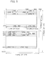
- the rate-converted data is applied to compression circuit 16 and recorded into compression circuit 16 by such format as shown in Fig. 5. That is to say, a MUSE signal for 1.5 lines is recorded per one line of HDVTR 2.
- One line of MUSE signal has 1200 samples because a MUSE signal of 480 samples is converted into data of 960 samples which is a doubled rate and further a sample for 4 clocks is converted into a sample of 5 clocks.
- data of 40.25 MHz recorded in compression circuit 16 is compressed by being read out with 74.25 MHz and converted into input rate of VTR 2.
- Fig. 6 is a block diagram illustrating a specific example of compression circuit 16.
- the compression circuit 16 includes memories 16a and 16b having storage capacity of data for 1 field, a switch circuit 16c switching through a write clock CK1 (one of control signals) from control device 5, and a switch circuit 16d switching in response to a read clock CK2 from control device 5.
- compression circuit 16 writes a signal from rate converter 15 in response to write clock CK1 with 40.5 MHz into memory 16a or 16b and reads out data written into memory 16a or 16b delimiting it for each 1.5 line in response to read clock CK2 with 74.25 MHz.
- a field memory of first-in first-out system may be employed as shown in Fig. 7.
- HDVTR 2 provided with data compressed by compression circuit 16 is in a synchronization state by synchronization signals (a horizontal pulse, a frame pulse, a 3-value synchronization signal and so forth) from control device 5.
- synchronization signals a horizontal pulse, a frame pulse, a 3-value synchronization signal and so forth
- data from compression circuit 16 are sequentially recorded.
- the data thus recorded in HDVTR 2 corresponds to a MUSE signal in field units, so that it is possible to extract data for each unit and process the same with simulator 3.
- an original MUSE signal can be recovered, and when it is processed by a simulator, the processed data can be D/A converted to produce a MUSE signal.
- synchronization is implemented by combinations of FF H , 00 H (8 bit data). More specifically, when 8 bits of data come in the order of FF H , 00 H , 00 H , it is recognized as a synchronization signal. In this case, synchronization with the HDVTR can not be provided by the MUSE adaptor of Fig. 3.
- Fig. 8 is a block diagram of a MUSE adaptor used for a HDVTR which provides synchronization by such data combinations
- Fig. 9 is a diagram for describing rate conversion of the MUSE adaptor of Fig. 8.
- the MUSE adaptor and the MUSE adaptor of Fig. 3 are different in that it includes a rate converter 15′ which combines bits in a way different from that in Fig. 4, a synchronization detecting circuit 26 for detecting whether 8 bits of data from rate converter 15′ is of a combination of FF H , 00 H , 00 H , and a synchronization signal adding circuit 27 for adding a synchronization signal (FF H , 00 H , 00 H ) to an output of compression circuit 16.
- FF H , 00 H , 00 H synchronization signal
- Data selected by selector 13 is converted as shown in Fig. 9 by rate converter 15′. That is, in data of 32.4 MHz, 10 bits x 4, the second lowest bit and the third lowest bit are placed at the fifth clock for conversion into data of 40.5 MHz, 8 bits x 5. If the converted data is of the order of the above-mentioned combination, one of two 00 H is converted into 01 H to break the combination of synchronization, and then it is provided to HDVTR 2. Then, FF H , 00 H , 00 H is added between compressed data (for example, between lines or between fields), which is recorded in HDVTR 2. When such conversion is made, the lowest bit or the second lowest bit of data of 10 bits is affected, but the image quality is not visually affected.
- a MUSE signal can also be digitally recorded substantially as it is similarly to the embodiment of Figs. 1-7. Also, the recorded data can be read out to be used as a signal source for simulation process evaluation.
Abstract
Description
- The present invention relates to MUSE (Multiple Sub-Nyquist Sampling Encoding) signal digital recording/reproducing apparatus for recording/reproducing MUSE signals in digital VTRs and an operation method thereof, and particularly to an adaptor for converting a MUSE signal in correspondence to recording/reproducing formats of a high definition television signal recording/reproducing device (hereinafter, referred to as a HDVTR) capable of digitally recording a high definition television signal.
- The MUSE system has been recently developed and the test broadcasting of high definition television signals has been started with the development of the MUSE system.
- The MUSE system means a system in which a high definition television signal is compressed to a signal with baseband width of approximately 8 MHz. A signal converted according to the system is referred to as a MUSE signal.
- For recording/reproducing a MUSE signal, two kinds of methods are presently proposed. One of them is a method for recording/reproducing a MUSE signal as it is by a VTR dedicated to MUSE signal, and another one is a method in which the rate of a MUSE signal is converted into the input format of a digital VTR of the standard system and it is recorded, and when reproducing, conversion opposite to that in recording is performed to produce a MUSE signal. The former method can record a MUSE signal as it is, so that the recorded signal can be extracted to evaluate the quality of the inputted MUSE signal. For manufacturing a VTR dedicated to MUSE signal, however, great amounts of time for development and cost are required. Accordingly, the latter method is introduced in which less time for development and less cost are required as compared to the former one. The latter method is disclosed in "ITEJ Technical Report Vol13. No.50 p.p.25-30, VTR′ 89-16C Oct. 1989".
- Fig. 10 is a simplified block diagram of the recording system described in the paper. The recording system includes a digital VTR (hereinafter, referred to as a VTR 50) of the SMPTE-D-1 standard, and an
adaptor 51 for converting a MUSE signal so that it applies to the input rate ofVTR 50. A MUSE signal dealt with herein is converted digital data of 16.2 MHz, 10 bits. - Said
adaptor 51 includes aninterface portion 52, arate converting portion 53 and asystem controller 54.Interface portion 52 performs re-arrangement of data corresponding to the standard ofVTR 50 and also adds a control code for controllingVTR 50.Rate converter 53 converts rate between an input source of MUSE signal andinterface portion 52.System controller 54 produces a signal for recording an inputted MUSE signal inVTR 50 in synchronization withVTR 50 and all control signals used insideadaptor 51. - Fig. 11 is a diagram for describing a rate converting operation of
adaptor 51. Referring to the figure, M denotes a higher bit and L denotes a lower bit. Firstly, a MUSE signal of 16.2 MHz, 10 bits is applied torate converter 53 and converted into digital data having the input rate of interface portion 52 (13.5MHz 8 bits x 1, 6.75MHz 8 bits x 2). The three time-divided digital data are converted into 27MHz 8 bits (the input rate of VTR 50) byinterface portion 52 and then provided toVTR 52. - As described above, since a MUSE signal of 16.2 MHz x 10 bits can be converted into digital data of 27 MHz x 8 bits which is the input rate of
VTR 50, even when the bit lengths of a recorded signal of VTR and a MUSE signal are different, the MUSE signal can be recorded in recording tape. - While frame frequency of a MUSE signal is 30 MHz, frame frequency in the NTSC system is 29.97 MHz. Since frame frequencies of the two are thus different, respective frames of MUSE signal recorded in
VTR 50 are simply handled as continuing signals as shown in Fig. 12. Also, regarding information amount, while it is 20M bite/second in a MUSE signal, it is 21.57M bite/second in a recorded signal ofVTR 50. Accordingly, the capacity ofVTR 50 is larger and data can be recorded without loss. Furthermore, it is described in the above-identified paper that a signal of double rate (32.4 MHz x 10 bits) can be recorded/reproduced by addingVTR 50 and a frame memory board. - Said adaptor is enough to simply record/reproduce a MUSE signal and to be used as a MUSE source. However, as described above, since frame frequencies of a MUSE signal and a recorded signal of VTR differ from each other, frame lock is impossible. Therefore,
coupling VTR 50 to a simulator for video signals, in processing recorded data in frame units, or in evaluating quality of a MUSE signal on the basis of recorded data, or in evaluating a system of data compression, a problem occurs. - The inventors of the present invention focused their attention on usage of a so-called HDVTR capable of recording with the same frame frequency as a MUSE signal and having a large recording/reproducing capacity. The HDVTR, however, uses only effective lines and effective picture elements of a high definition television signal as record information, so that it has a problem that a MUSE signal having different numbers of picture elements and lines from those of baseband can not be directly recorded.
- It is an object of the present invention to provide a MUSE signal digital recording/reproducing apparatus capable of recording/reproducing a MUSE signal in a frame-lock state using a HDVTR and also capable of recording/reproducing with a rate higher than conventional cases.
- Briefly stated, the present invention is a MUSE signal digital recording/reproducing apparatus which converts a MUSE signal into a digital signal and records the same, and reproduces the recorded data, including a recording/reproducing device, a first A/D converter, a frequency converter, a second A/D converter, a selector, a rate converter, and an extracting device.
- The recording/reproducing device can digitally record a high definition television signal. The first A/D converter A/D converts synchronizing MUSE signals of two types with a sample signal in synchronization with the MUSE signal and predetermined quantization characteristics. The frequency converter applies multiplex processing to the data A/D converted by the first A/D converter to convert it into doubled frequency. The second A/D converter A/D converts a MUSE signal of one type with a sample signal of frequency which is double of said sample signal. The selector selects one of the signal multiplex-processed by the frequency converter and an output of the second converter. The rate converter converts a rate of the selected output corresponding to recording/reproducing frequencies and phase of the recording/reproducing device and the converted data is recorded into the recording/reproducing device. The extracting device performs operation opposite to that in the recording operation for the data recorded in the recording/reproducing device to extract MUSE signals of two types or a MUSE signal of one type.
- In operation, a recording/reproducing device capable of digitally recording effective lines and effective picture elements of a high definition television signal has a recording capacity which is enough to record/reproduce a MUSE signal with a rate higher than conventional cases. However, since the recording/reproducing device can not record/reproduce a MUSE signal having different numbers of picture elements and lines than those of a baseband signal as it is, the following processings are performed. That is, data obtained as a result of a multiplex processing of A/D converted values of two types of MUSE signals or data A/D converted at a rate which is a double of one type MUSE signal is converted in rate corresponding to recording/reproducing frequency and phase of the recording/reproducing device. By thus providing rate-converted digital data to the recording/reproducing device, a MUSE signal can be recorded in a frame-lock state. Also, it is possible to reproduce a MUSE signal by applying a conversion opposite to that in the recording operation and use the same as a MUSE signal for simulation. Furthermore, as the frame-lock is possible, recorded data can be extracted and readily processed in frame units to perform quality evaluation of the MUSE signal by using a computer.
- The foregoing and other objects, features, aspects and advantages of the present invention will become more apparent from the following detailed description of the present invention when taken in conjunction with the accompanying drawings.
- Fig. 1 is a block diagram illustrating one embodiment of the present invention.
- Fig. 2 is a diagram for describing recording format of a HDVTR.
- Fig. 3 is a block diagram illustrating details of a MUSE adaptor.
- Fig. 4 is a diagram for describing a rate converting system of a rate converter.
- Fig. 5 is a diagram for describing recording format of a compression circuit.
- Fig. 6 is a specific block diagram of a compression circuit.
- Fig. 7 is a block diagram illustrating a modification of a compression circuit.
- Fig. 8 is a block diagram illustrating a modified example of a MUSE adaptor.
- Fig. 9 is a diagram for describing a rate converting system of the MUSE adaptor shown in Fig. 8.
- Fig. 10 is a block diagram of a conventional MUSE signal recording system.
- Fig. 11 is a diagram for describing a rate converting system of the system shown in Fig. 10.
- Fig. 12 is a diagram illustrating recording format to be recorded in a VTR by the system of Fig. 10.
- Fig. 1 is a diagram illustrating one embodiment of a MUSE signal digital recording/reproducing apparatus according to the present invention. Referring to the figure, the MUSE signal digital recording/reproducing apparatus includes a
MUSE adaptor 1, aHDVTR 2 and asimulator 3. A-F denote MUSE signals, respectively. - In recording,
MUSE adaptor 1 converts externally inputted MUSE signals A and B or a MUSE signal C into digital data corresponding to the recording/reproducing frequency and phase ofHDVTR 2 and applies the digital data to a luminance signal input terminal Y ofVTR 2. In reproducing, it performs conversion opposite to that in recording for the data from a luminance signal output terminal Y ofHDVTR 2 to output MUSE signals D and E or a MUSE signal F. When two types of MUSE signals A and B are simultaneously inputted, it A/D converts the MUSE signal A and B with sample frequency 16.2 MHz and quantization characteristic 10 bits and converts the A/D converted data into 32.4 MHz x 10 bits by multiplex processing. Also, when a type of MUSE signal C is inputted, it performs A/D conversion with sample frequency of 32.4 MHz and quantization characteristic of 10 bits. -
HDVTR 2, which can record and reproduce effective lines and effective picture elements of a high definition television signal, is used for recording/reproducing a MUSE signal, for example, converted in rate byMUSE adaptor 1 in this embodiment. -
Simulator 3 captures recorded digital data of a MUSE signal inHDVTR 2 and applies predetermined processings to produce a new signal, or makes an image by the captured digital data displayed in a monitor not shown to evaluate quality of a MUSE signal, for example. - Next,
HDVTR 2 will be described in further detail.HDVTR 2 can record/reproduce effective lines and effective picture elements of a high definition television signal as stated above. InHDVTR 2 used in this embodiment, the sample frequency is 74.25 MHz and the quantization characteristic is 8 bits, wherein one frame is recorded with frequency of 30 Hz which is the same as frame frequency of a high definition television signal. The recording format is shown in Fig. 2. A portion surrounded by an alternate long and short dash line in Fig. 2 indicates one frame of a high definition television signal. The number of lines per one frame of a high definition television signal is 1125 and the number of samples per one line is 2200. The lines Number 1-38 and 557-601 include vertical synchronizing pulse and the like, and the lines Number 1120-1125 include a control signal and the like. The samples Number 1-281 include horizontal synchronizing pulses and the like. A portion surrounded by a solid line indicates effective lines and sample values recorded inHDVTR 2. That is to say, information for image is recorded in lines Number 38-557, 601-1120 and samples Number 281-2200 in a high definition television signal. Accordingly, the recording capacity ofHDVTR 2 is 1920 x 1040 byte/frame. - Next, details of
MUSE adaptor 1 will be described referring to the block diagram of Fig. 3.MUSE adaptor 1 performs A/D conversion for simultaneously inputted two types of MUSE signals A and B with sample frequency 16.2 MHz and quantization characteristic of 10 bits, and multiplex-processes the A/D converted values to 32.4MHz 10 bits. Also, for MUSE signal C, it performs A/D conversion with sample frequency 32.4 MHz and quantization characteristic 10 bits. The quantity of information of a MUSE signal sampled byMUSE adaptor 1 and the record capacity ofHDVTR 2 are shown in Table 1. The information quantity and record capacity are obtained from the above-mentioned signal rates.
- From Table 1, it is recognized that the
HDVTR 2 has record capacity which is enough for recording a MUSE signal of 32.4 MHz and 10 bits without loss of data. - Referring to Fig. 3,
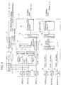
MUSE adaptor 1 includes asignal processing device 4 for converting MUSE signals A and B or a MUSE signal C into data of 74.25MHz 8 bits, and acontrol device 5 for detecting a synchronization signal from an A/D converted value of a MUSE signal and controllingsignal processing device 4 andHDVTR 2 on the basis of the detected synchronization signal.Signal processing device 4 includes an A/D converters equalizers selectors multiplexer 14, arate converter 15 connected to an output of the multiplexer, acompression circuit 16 connected to an output ofrate converter 15, anexpansion circuit 17 provided with digital data fromHDVTR 2, arate converter 18 connected to an output ofexpansion circuit 17, areverse multiplexer 19 for processing an output ofrate converter 18, and D/A converters multiplexer 19 andrate converter 18. Thecontrol device 5 includes aselector 23, a PLL (Phase Locked Loop)circuit 24 and acontrol 25. - Next, operation of the MUSE signal digital recording/reproducing apparatus shown in Figs. 1 through 3 will be described. Two types of MUSE signals A, B are respectively converted into digital data of 16.2
MHz 10 bits by A/D converters device 5 and also provided toselectors equalizers device 5 is applied toPLL circuit 24 throughselector 23, synchronized in phase with a record/reproduce clock signal ofHDVTR 2 byPLL circuit 24, and applied tocontroller 25 thereafter.Controller 25 provides synchronization signals (a horizontal pulse, a frame pulse, a three-value synchronization signal, and so forth) for controllingHDVTR 2 on the basis of a signal synchronized in phase fromPLL circuit 24, and also outputs a control signal for controllingsignal processing device 4. - The
selectors equalizers D converters selectors multiplexer 14 and then applied toselector 13. - Also, the one type of MUSE signal C, after being converted into a digital signal with sample frequency 32.4 MHz and quantization characteristic 10 bits by A/
D converter 8, is applied toselector 13.Selector 13 selects one of data compressed bymultiplexer 14 and an output of A/D converter 8, and provides it to rateconverter 15.Rate converter 15 converts rate of the applied digital data as shown in Fig. 4. That is to say,rate converter 15 places the lower 2 bits in the data of 32.4 MH, 10 bits x 4 clocks at the fifth clock to convert it into data of 40.5 MHz, 8 bits x 5 clocks. - The rate-converted data is applied to
compression circuit 16 and recorded intocompression circuit 16 by such format as shown in Fig. 5. That is to say, a MUSE signal for 1.5 lines is recorded per one line ofHDVTR 2. One line of MUSE signal has 1200 samples because a MUSE signal of 480 samples is converted into data of 960 samples which is a doubled rate and further a sample for 4 clocks is converted into a sample of 5 clocks. Thus, data of 40.25 MHz recorded incompression circuit 16 is compressed by being read out with 74.25 MHz and converted into input rate ofVTR 2. - The data compressing operation will be described in more detail using Fig. 6. Fig. 6 is a block diagram illustrating a specific example of
compression circuit 16. Thecompression circuit 16 includesmemories switch circuit 16c switching through a write clock CK1 (one of control signals) fromcontrol device 5, and a switch circuit 16d switching in response to a read clock CK2 fromcontrol device 5. By introducing such a structure,compression circuit 16 writes a signal fromrate converter 15 in response to write clock CK1 with 40.5 MHz intomemory memory -
HDVTR 2 provided with data compressed bycompression circuit 16 is in a synchronization state by synchronization signals (a horizontal pulse, a frame pulse, a 3-value synchronization signal and so forth) fromcontrol device 5. In this synchronization state, data fromcompression circuit 16 are sequentially recorded. The data thus recorded inHDVTR 2 corresponds to a MUSE signal in field units, so that it is possible to extract data for each unit and process the same withsimulator 3. In reproducing, by performing conversion opposite to that in recording, an original MUSE signal can be recovered, and when it is processed by a simulator, the processed data can be D/A converted to produce a MUSE signal. - Although a case in which
HDVTR 2 introduces the external synchronization system has been described in the above description, in a certain HDVTR, synchronization is implemented by combinations of FFH, 00H (8 bit data). More specifically, when 8 bits of data come in the order of FFH, 00H, 00H, it is recognized as a synchronization signal. In this case, synchronization with the HDVTR can not be provided by the MUSE adaptor of Fig. 3. - Fig. 8 is a block diagram of a MUSE adaptor used for a HDVTR which provides synchronization by such data combinations, and Fig. 9 is a diagram for describing rate conversion of the MUSE adaptor of Fig. 8. Referring to Fig. 8, the MUSE adaptor and the MUSE adaptor of Fig. 3 are different in that it includes a
rate converter 15′ which combines bits in a way different from that in Fig. 4, asynchronization detecting circuit 26 for detecting whether 8 bits of data fromrate converter 15′ is of a combination of FFH, 00H, 00H, and a synchronizationsignal adding circuit 27 for adding a synchronization signal (FFH, 00H, 00H) to an output ofcompression circuit 16. The same characters are allotted to the same circuits as those in Fig. 3, and description thereof may not be repeated. - Next, operation of the MUSE adaptor shown in Fig. 8 will be described. Data selected by
selector 13 is converted as shown in Fig. 9 byrate converter 15′. That is, in data of 32.4 MHz, 10 bits x 4, the second lowest bit and the third lowest bit are placed at the fifth clock for conversion into data of 40.5 MHz, 8 bits x 5. If the converted data is of the order of the above-mentioned combination, one of two 00H is converted into 01H to break the combination of synchronization, and then it is provided toHDVTR 2. Then, FFH, 00H, 00H is added between compressed data (for example, between lines or between fields), which is recorded inHDVTR 2. When such conversion is made, the lowest bit or the second lowest bit of data of 10 bits is affected, but the image quality is not visually affected. - In the embodiment of Figs. 8 and 9, a MUSE signal can also be digitally recorded substantially as it is similarly to the embodiment of Figs. 1-7. Also, the recorded data can be read out to be used as a signal source for simulation process evaluation.
- Although the present invention has been described and illustrated in detail, it is clearly understood that the same is by way of illustration and example only and is not to be taken by way of limitation, the spirit and scope of the present invention being limited only by the terms of the appended claims.
- There are described above novel features which the skilled man will appreciate give rise to advantages. These are each independent aspects of the invention to be covered by the present application, irrespective of whether or not they are included within the scope of the following claims.
Claims (11)
- A MUSE signal digital recording/reproducing apparatus for converting a MUSE signal into a digital signal and recording the same, and reproducing the recorded data, comprising:
recording/reproducing means (2) capable of digitally recording a high definition television signal;
at least two first A/D converting means (6, 7) for A/D converting each of externally produced at least two types of synchronizing MUSE signals with a sample signal synchronizing with the MUSE signal and predetermined quantization characteristic;
means (14) for converting respective data A/D converted by said at least two A/D converting means into doubled frequency by multiplex processing;
second A/D converting means (8) for A/D converting externally produced one type of MUSE signal with frequency of double of said sample signal;
means (13) for selecting one of said multiplex-processed signal and an output signal of said second A/D converting means;
rate converting means (15, 16) for converting in rate said selected signal corresponding to recording/reproducing frequency and phase of said recording/reproducing means and making the same recorded in said recording/reproducing means;
means (17, 18, 19, 20, 21, 22) for extracting two types of MUSE signals or one type of MUSE signal by performing operation opposite to said recording operation for data recorded in said recording/reproducing means; and
means (5) for producing a control signal for controlling said rate converting means and said recording/reproducing means on the basis of an output of said first or second A/D converting means. - The MUSE signal recording/reproducing apparatus according to claim 1, wherein said recording/reproducing means includes a video tape recorder (2) capable of recording/reproducing an effective line and an effective picture element of a high definition television signal.
- The MUSE signal recording/reproducing apparatus according to claim 2, wherein said video tape recorder (2) has a recording format (Fig. 2) for recording 1 frame with frequency the same as frame frequency of a high definition television signal.
- The MUSE signal recording/reproducing apparatus according to claim 3, wherein said video tape recorder (2) includes a device which implements synchronization by a synchronization signal included in a high definition television signal, and
said rate converting means (15, 16) includes a device (15) for converting rate of data from said selecting means corresponding to recording/reproducing frequency and phase characteristics of said recording/reproducing means. - The MUSE signal recording/reproducing apparatus according to claim 4, wherein said rate converting means (15, 16) includes means (15) for converting in rate the multiplex- processed signal or an output of second A/D converting means selected by said selecting means corresponding to frequency and phase of said recording/reproducing means, and means (16) for compressing the rate-converted data.
- The MUSE signal recording/reproducing apparatus according to claim 5, wherein
said compressing means (16) includes at least two memory means (16a, 15b) each having storage capacity for 1 field, and
data is written into each of said memory means and the written data is read therefrom in response to write and read control signals (CK1, CK2) from said control means (5). - The MUSE signal recording/reproducing apparatus according to claim 6, wherein said read control signal has frequency higher than said write control signal.
- The MUSE signal recording/reproducing apparatus according to claim 5, wherein said compressing means (16) includes memory means of a first-in first-out type.
- The MUSE signal recording/reproducing apparatus according to claim 3, wherein
said video tape recorder (2) includes a device which detects predetermined data combination included in a high definition television signal and recognizes it as a synchronization signal, and
said rate converting means includes detecting means (26) of combination data for detecting the predetermined data combination and data re-combining means (15′) for recombining the combination data into another data. - A method of operating a MUSE signal digital recording/reproducing apparatus having recording/reproducing means (2) capable of digitally recording and reproducing a high definition television signal, comprising the steps of:
A/D converting each of externally produced at least two types of synchronous MUSE signals with a sample signal synchronizing with the MUSE signal and predetermined quantization characteristic;
converting each said A/D converted data into doubled frequency by multiplex processing;
A/D converting externally produced one type of MUSE signal with frequency which is a double of said sample signal;
selecting one of said multiplex-processed signal and the signal A/D converted with said doubled frequency;
converting in rate said selected signal corresponding to frequency and phase of said recording/reproducing means;
recording said rate converted signal into said recording/reproducing means; and
extracting two types of MUSE signals or one type of MUSE signal by applying operation opposite to said recording operation to data recorded in said recording/reproducing means. - A MUSE signal recording/reproducing apparatus for converting a MUSE signal into a digital signal and recording the same, and for reproducing the recorded signal, said apparatus including a HDVTR (2), a signal processing device (4), and a control device (5) for controlling the HDVTR (2) and the signal processing device (4), the signal processing device (4) being operable to perform A/D conversion and multiplex processing of two simultaneously supplied MUSE signals to convert the same into a signal having a frequency double that of a MUSE signal, and further to perform rate conversion corresponding to the recording frequency and phase of the HDVTR, the HDVTR (2) being operable to record the rate-converted data.
Applications Claiming Priority (2)
| Application Number | Priority Date | Filing Date | Title |
|---|---|---|---|
| JP37565/91 | 1991-03-04 | ||
| JP3037565A JP2603162B2 (en) | 1991-03-04 | 1991-03-04 | MUSE signal digital recording / playback device |
Publications (2)
| Publication Number | Publication Date |
|---|---|
| EP0502708A1 true EP0502708A1 (en) | 1992-09-09 |
| EP0502708B1 EP0502708B1 (en) | 1996-09-18 |
Family
ID=12501048
Family Applications (1)
| Application Number | Title | Priority Date | Filing Date |
|---|---|---|---|
| EP92301849A Expired - Lifetime EP0502708B1 (en) | 1991-03-04 | 1992-03-04 | Muse signal digital recording/reproducing apparatus and operating method thereof |
Country Status (4)
| Country | Link |
|---|---|
| US (1) | US5220435A (en) |
| EP (1) | EP0502708B1 (en) |
| JP (1) | JP2603162B2 (en) |
| DE (1) | DE69213788T2 (en) |
Cited By (1)
| Publication number | Priority date | Publication date | Assignee | Title |
|---|---|---|---|---|
| EP0617565A1 (en) * | 1993-03-22 | 1994-09-28 | Matsushita Electric Industrial Co., Ltd. | Video signal processing apparatus and its method |
Families Citing this family (6)
| Publication number | Priority date | Publication date | Assignee | Title |
|---|---|---|---|---|
| JP3287875B2 (en) * | 1992-05-20 | 2002-06-04 | ソニー株式会社 | Video tape recorder |
| US5285262A (en) * | 1992-05-26 | 1994-02-08 | The United States Of America As Represented By The Secretary Of The Army | High resolution video acquisition system |
| JPH06150568A (en) * | 1992-11-06 | 1994-05-31 | Sony Corp | Data recording device |
| CA2115976C (en) * | 1993-02-23 | 2002-08-06 | Saiprasad V. Naimpally | Digital high definition television video recorder with trick-play features |
| KR940026915A (en) * | 1993-05-24 | 1994-12-10 | 오오가 노리오 | Digital video signal recording device and playback device and recording method |
| US10231580B2 (en) | 2014-07-07 | 2019-03-19 | GPCP IP Holdings LLC. | Multiple orifice nozzle with cavity |
Citations (5)
| Publication number | Priority date | Publication date | Assignee | Title |
|---|---|---|---|---|
| EP0377471A1 (en) * | 1989-01-06 | 1990-07-11 | Sanyo Electric Co., Ltd. | Digital recording and reproducing apparatus for muse signal |
| US4963992A (en) * | 1988-01-29 | 1990-10-16 | Hitachi, Ltd. | Apparatus for recording/reproducing digital video signals in both a standard mode and a long playing mode |
| DE4014744A1 (en) * | 1989-05-09 | 1990-11-15 | Mitsubishi Electric Corp | SYSTEM AND DEVICE FOR DIGITAL VIDEO SIGNAL RECORDING |
| EP0404383A2 (en) * | 1989-06-20 | 1990-12-27 | Sharp Kabushiki Kaisha | Apparatus for recording and reproducing video signals of high resolution image |
| WO1991003909A1 (en) * | 1989-09-07 | 1991-03-21 | Advanced Television Test Center, Inc. | Multiple hdtv format digital signal converter |
Family Cites Families (2)
| Publication number | Priority date | Publication date | Assignee | Title |
|---|---|---|---|---|
| JP2805095B2 (en) * | 1989-10-31 | 1998-09-30 | ソニー株式会社 | Video signal recording device |
| US5063445A (en) * | 1990-04-19 | 1991-11-05 | Nippon Hoso Kyokai | Multiple sub-sampling transmitting/receiving system performing interfield and interframe offset sub-sampling of a broad bandwidth television signal |
-
1991
- 1991-03-04 JP JP3037565A patent/JP2603162B2/en not_active Expired - Lifetime
-
1992
- 1992-03-03 US US07/845,039 patent/US5220435A/en not_active Expired - Fee Related
- 1992-03-04 DE DE69213788T patent/DE69213788T2/en not_active Expired - Fee Related
- 1992-03-04 EP EP92301849A patent/EP0502708B1/en not_active Expired - Lifetime
Patent Citations (5)
| Publication number | Priority date | Publication date | Assignee | Title |
|---|---|---|---|---|
| US4963992A (en) * | 1988-01-29 | 1990-10-16 | Hitachi, Ltd. | Apparatus for recording/reproducing digital video signals in both a standard mode and a long playing mode |
| EP0377471A1 (en) * | 1989-01-06 | 1990-07-11 | Sanyo Electric Co., Ltd. | Digital recording and reproducing apparatus for muse signal |
| DE4014744A1 (en) * | 1989-05-09 | 1990-11-15 | Mitsubishi Electric Corp | SYSTEM AND DEVICE FOR DIGITAL VIDEO SIGNAL RECORDING |
| EP0404383A2 (en) * | 1989-06-20 | 1990-12-27 | Sharp Kabushiki Kaisha | Apparatus for recording and reproducing video signals of high resolution image |
| WO1991003909A1 (en) * | 1989-09-07 | 1991-03-21 | Advanced Television Test Center, Inc. | Multiple hdtv format digital signal converter |
Cited By (2)
| Publication number | Priority date | Publication date | Assignee | Title |
|---|---|---|---|---|
| EP0617565A1 (en) * | 1993-03-22 | 1994-09-28 | Matsushita Electric Industrial Co., Ltd. | Video signal processing apparatus and its method |
| US5646695A (en) * | 1993-03-22 | 1997-07-08 | Matsushita Electric Industrial Co., Ltd. | Video signal processing method and apparatus for use with plural television systems |
Also Published As
| Publication number | Publication date |
|---|---|
| DE69213788T2 (en) | 1997-04-10 |
| JPH04275794A (en) | 1992-10-01 |
| EP0502708B1 (en) | 1996-09-18 |
| DE69213788D1 (en) | 1996-10-24 |
| US5220435A (en) | 1993-06-15 |
| JP2603162B2 (en) | 1997-04-23 |
Similar Documents
| Publication | Publication Date | Title |
|---|---|---|
| US4963992A (en) | Apparatus for recording/reproducing digital video signals in both a standard mode and a long playing mode | |
| CA2066413A1 (en) | Multiple hdtv format digital signal converter | |
| KR0178766B1 (en) | Apparatus for digital interface with transmission function of a non-compression digital data | |
| US5617218A (en) | Bi-directional television and motion picture film to magnetic tape format digital signal converter | |
| US5019908A (en) | Apparatus and method for reducing flickering in a still video frame in a digital image processing system | |
| JPH0759058A (en) | Transmission device of digital image signal | |
| EP0502708B1 (en) | Muse signal digital recording/reproducing apparatus and operating method thereof | |
| EP0549108B1 (en) | Digital video signal switching with data rate conversion | |
| JPH05268561A (en) | Multi-channel recording/reproducing device | |
| US6192190B1 (en) | Digital image recording and/or reproducing apparatus using a plurality of compression methods | |
| US4937668A (en) | Method and apparatus for transmitting video information | |
| KR20000064963A (en) | Method and apparatus for recording and playing video images | |
| JPH07135635A (en) | Video signal processing device | |
| US6009227A (en) | HDTV digital recorder with compressed image data inserted in a video signal that corresponds to a video interface standard | |
| JPH06181580A (en) | Digital vtr | |
| JPH0251983A (en) | Still picture recorder | |
| US6788879B1 (en) | Image signal processing apparatus | |
| EP0515180B1 (en) | Digital component video signal processor for two data rates | |
| JP2000261759A (en) | Signal recording and reproducing device | |
| JP2717746B2 (en) | Video facsimile machine | |
| KR0141135B1 (en) | Apparatus for converting into adaptive regenerate process | |
| JP3456601B2 (en) | Video recording device, video reproducing device and method thereof | |
| JPH05236425A (en) | Magnetic recording and reproducing device for wide aspect ratio video signal | |
| JP3136875B2 (en) | Data processing device | |
| JP3049835B2 (en) | Video signal recording and playback device |
Legal Events
| Date | Code | Title | Description |
|---|---|---|---|
| PUAI | Public reference made under article 153(3) epc to a published international application that has entered the european phase |
Free format text: ORIGINAL CODE: 0009012 |
|
| AK | Designated contracting states |
Kind code of ref document: A1 Designated state(s): DE FR GB |
|
| 17P | Request for examination filed |
Effective date: 19920903 |
|
| 17Q | First examination report despatched |
Effective date: 19940628 |
|
| GRAH | Despatch of communication of intention to grant a patent |
Free format text: ORIGINAL CODE: EPIDOS IGRA |
|
| GRAH | Despatch of communication of intention to grant a patent |
Free format text: ORIGINAL CODE: EPIDOS IGRA |
|
| GRAA | (expected) grant |
Free format text: ORIGINAL CODE: 0009210 |
|
| AK | Designated contracting states |
Kind code of ref document: B1 Designated state(s): DE FR GB |
|
| REF | Corresponds to: |
Ref document number: 69213788 Country of ref document: DE Date of ref document: 19961024 |
|
| ET | Fr: translation filed | ||
| PLBE | No opposition filed within time limit |
Free format text: ORIGINAL CODE: 0009261 |
|
| STAA | Information on the status of an ep patent application or granted ep patent |
Free format text: STATUS: NO OPPOSITION FILED WITHIN TIME LIMIT |
|
| 26N | No opposition filed | ||
| REG | Reference to a national code |
Ref country code: GB Ref legal event code: IF02 |
|
| PGFP | Annual fee paid to national office [announced via postgrant information from national office to epo] |
Ref country code: GB Payment date: 20020306 Year of fee payment: 11 |
|
| PGFP | Annual fee paid to national office [announced via postgrant information from national office to epo] |
Ref country code: FR Payment date: 20020312 Year of fee payment: 11 |
|
| PGFP | Annual fee paid to national office [announced via postgrant information from national office to epo] |
Ref country code: DE Payment date: 20020320 Year of fee payment: 11 |
|
| PG25 | Lapsed in a contracting state [announced via postgrant information from national office to epo] |
Ref country code: GB Free format text: LAPSE BECAUSE OF NON-PAYMENT OF DUE FEES Effective date: 20030304 |
|
| PG25 | Lapsed in a contracting state [announced via postgrant information from national office to epo] |
Ref country code: DE Free format text: LAPSE BECAUSE OF NON-PAYMENT OF DUE FEES Effective date: 20031001 |
|
| GBPC | Gb: european patent ceased through non-payment of renewal fee | ||
| PG25 | Lapsed in a contracting state [announced via postgrant information from national office to epo] |
Ref country code: FR Free format text: LAPSE BECAUSE OF NON-PAYMENT OF DUE FEES Effective date: 20031127 |
|
| REG | Reference to a national code |
Ref country code: FR Ref legal event code: ST |