EP0502650B1 - Method and apparatus for mounting ancillary equipment to a furnace - Google Patents
Method and apparatus for mounting ancillary equipment to a furnace Download PDFInfo
- Publication number
- EP0502650B1 EP0502650B1 EP92301671A EP92301671A EP0502650B1 EP 0502650 B1 EP0502650 B1 EP 0502650B1 EP 92301671 A EP92301671 A EP 92301671A EP 92301671 A EP92301671 A EP 92301671A EP 0502650 B1 EP0502650 B1 EP 0502650B1
- Authority
- EP
- European Patent Office
- Prior art keywords
- furnace
- hole
- exterior
- refractory
- wall
- Prior art date
- Legal status (The legal status is an assumption and is not a legal conclusion. Google has not performed a legal analysis and makes no representation as to the accuracy of the status listed.)
- Expired - Lifetime
Links
- 238000000034 method Methods 0.000 title claims description 22
- 239000011521 glass Substances 0.000 claims description 14
- 238000002844 melting Methods 0.000 claims description 11
- 230000008018 melting Effects 0.000 claims description 11
- 238000003780 insertion Methods 0.000 claims description 9
- 230000037431 insertion Effects 0.000 claims description 9
- 239000011819 refractory material Substances 0.000 claims description 5
- 230000000063 preceeding effect Effects 0.000 claims 1
- 239000006060 molten glass Substances 0.000 description 7
- 238000005816 glass manufacturing process Methods 0.000 description 4
- 238000010438 heat treatment Methods 0.000 description 4
- 238000010276 construction Methods 0.000 description 3
- 230000009194 climbing Effects 0.000 description 2
- 230000000694 effects Effects 0.000 description 2
- 238000007796 conventional method Methods 0.000 description 1
- 229910003460 diamond Inorganic materials 0.000 description 1
- 239000010432 diamond Substances 0.000 description 1
- 238000011065 in-situ storage Methods 0.000 description 1
- VYPSYNLAJGMNEJ-UHFFFAOYSA-N silicon dioxide Inorganic materials O=[Si]=O VYPSYNLAJGMNEJ-UHFFFAOYSA-N 0.000 description 1
- 239000000377 silicon dioxide Substances 0.000 description 1
- XLYOFNOQVPJJNP-UHFFFAOYSA-N water Substances O XLYOFNOQVPJJNP-UHFFFAOYSA-N 0.000 description 1
Images

Classifications
-
- C—CHEMISTRY; METALLURGY
- C03—GLASS; MINERAL OR SLAG WOOL
- C03B—MANUFACTURE, SHAPING, OR SUPPLEMENTARY PROCESSES
- C03B5/00—Melting in furnaces; Furnaces so far as specially adapted for glass manufacture
- C03B5/16—Special features of the melting process; Auxiliary means specially adapted for glass-melting furnaces
-
- H—ELECTRICITY
- H05—ELECTRIC TECHNIQUES NOT OTHERWISE PROVIDED FOR
- H05B—ELECTRIC HEATING; ELECTRIC LIGHT SOURCES NOT OTHERWISE PROVIDED FOR; CIRCUIT ARRANGEMENTS FOR ELECTRIC LIGHT SOURCES, IN GENERAL
- H05B3/00—Ohmic-resistance heating
- H05B3/02—Details
- H05B3/03—Electrodes
-
- C—CHEMISTRY; METALLURGY
- C03—GLASS; MINERAL OR SLAG WOOL
- C03B—MANUFACTURE, SHAPING, OR SUPPLEMENTARY PROCESSES
- C03B5/00—Melting in furnaces; Furnaces so far as specially adapted for glass manufacture
- C03B5/02—Melting in furnaces; Furnaces so far as specially adapted for glass manufacture in electric furnaces, e.g. by dielectric heating
- C03B5/027—Melting in furnaces; Furnaces so far as specially adapted for glass manufacture in electric furnaces, e.g. by dielectric heating by passing an electric current between electrodes immersed in the glass bath, i.e. by direct resistance heating
-
- C—CHEMISTRY; METALLURGY
- C03—GLASS; MINERAL OR SLAG WOOL
- C03B—MANUFACTURE, SHAPING, OR SUPPLEMENTARY PROCESSES
- C03B5/00—Melting in furnaces; Furnaces so far as specially adapted for glass manufacture
- C03B5/16—Special features of the melting process; Auxiliary means specially adapted for glass-melting furnaces
- C03B5/42—Details of construction of furnace walls, e.g. to prevent corrosion; Use of materials for furnace walls
-
- F—MECHANICAL ENGINEERING; LIGHTING; HEATING; WEAPONS; BLASTING
- F27—FURNACES; KILNS; OVENS; RETORTS
- F27D—DETAILS OR ACCESSORIES OF FURNACES, KILNS, OVENS, OR RETORTS, IN SO FAR AS THEY ARE OF KINDS OCCURRING IN MORE THAN ONE KIND OF FURNACE
- F27D1/00—Casings; Linings; Walls; Roofs
- F27D1/14—Supports for linings
- F27D1/145—Assembling elements
-
- H—ELECTRICITY
- H05—ELECTRIC TECHNIQUES NOT OTHERWISE PROVIDED FOR
- H05B—ELECTRIC HEATING; ELECTRIC LIGHT SOURCES NOT OTHERWISE PROVIDED FOR; CIRCUIT ARRANGEMENTS FOR ELECTRIC LIGHT SOURCES, IN GENERAL
- H05B3/00—Ohmic-resistance heating
- H05B3/02—Details
- H05B3/04—Waterproof or air-tight seals for heaters
-
- Y—GENERAL TAGGING OF NEW TECHNOLOGICAL DEVELOPMENTS; GENERAL TAGGING OF CROSS-SECTIONAL TECHNOLOGIES SPANNING OVER SEVERAL SECTIONS OF THE IPC; TECHNICAL SUBJECTS COVERED BY FORMER USPC CROSS-REFERENCE ART COLLECTIONS [XRACs] AND DIGESTS
- Y10—TECHNICAL SUBJECTS COVERED BY FORMER USPC
- Y10S—TECHNICAL SUBJECTS COVERED BY FORMER USPC CROSS-REFERENCE ART COLLECTIONS [XRACs] AND DIGESTS
- Y10S65/00—Glass manufacturing
- Y10S65/04—Electric heat
Definitions
- This invention relates to a glass melting furnace and to a method and apparatus for mounting ancillary equipment to a furnace for operation within the furnace environment and in particular, to a method and apparatus for mounting ancillary equipment to the furnace from the exterior of the furnace.
- the mounting of refractory blocks necessary for the mounting of certain types of ancillary equipment, such as heating electrodes, has to be carried out at a cold repair. This requires taking the furnace off line and in order to effect the mounting removing the glass from the furnace at least in the vicinity of the work area. The refractory blocks can then be mounted from within the furnace.
- the present invention is concerned with providing a method of mounting ancillary equipment into the furnace and reducing, if not overcoming, the above mentioned problems.
- a method of mounting a refractory block member in a wall of a glass melting furnace from the exterior of the furnace the refractory block member being a mounting member adapted to receive ancillary equipment which may be inserted from the exterior of the furnace for use in the furnace environment, the method being comprising: forming a partial distance through the wall of the furnace from the exterior thereof a first hole of a first cross-sectional area; forming completely through the wall of the furnace from the exterior thereof, as an extension of the first hole, a second hole of smaller cross-sectional area than the first hole, thereby forming a stepped opening through the wall of the furnace; and securing in said stepped opening a block member having an inner portion adapted to fit closely with the second hole and an outer portion adapted to fit closely with the first hole, characterised in that a displaceable plug is located at an inner end of a throughbore extending longitudinally through the refractory block member, the plug being displaceable from the inner end of
- the advantages of the present invention over the previously employed method mainly result from the fact that the mounting of the refractory blocks which enable the mounting of ancillary equipment is carried out from the exterior of the furnace, normally during a cold repair, and therefore removes the need for workmen climbing about and operating heavy machinery within the furnace. Further, as a hole is drilled through the refractory tile within the furnace in the mounting procedure, no damage is caused to the refractory tiles surrounding the drilled hole. As a consequence of this the previously mentioned problems are to a substantial degree avoided, and, therefore, it is possible to repair or upgrade furnaces at relatively low cost and quickly.
- a refractory block or refractory blocks are provided in a furnace in accordance with the present invention during a standard cold shut down, for example, a cold repair.
- French patent specification 965134 shows an electrode in a glass melting furnace where the electrode is mounted in a step shaped water cooled box. It would however require mounting of the electrode at the same time as the box was installed and it provides no refractory block with a displaceable plug to allow insertion of ancillary equipment at a later time.
- the hole bored through the wall of the furnace from the exterior does not extend through the refractory lining of the furnace and a second hole of narrower diameter is bored through the refractory lining of the furnace so that its longitudinal axis is coaxial with the hole bored through the wall of the furnace.
- a single refractory block is inserted into the hole or holes bored through the furnace wall and refractory lining of the furnace, the refractory block being shaped and sized so that it forms a good surface contact with the surrounding surfaces after insertion, and is also provided with a central longitudinally extending throughbore to enable mounting of the ancillary equipment.
- the throughbore provided in the refractory block is, preferably, of constant diameter.
- the throughbore may have a stepped or tapered profile.
- the mounting of ancillary equipment into the furnace is preferably achieved by inserting the ancillary equipment into the furnace by means of the throughbore in the refractory block, and connecting up the ancillary equipment.
- the single refractory block is provided with a plug means located in the throughbore at the end of the refractory block inserted into the furnace. Therefore, the plug means comes into contact with the molten glass within the furnace during operation of the furnace, and consequently the plug means acts to prevent the flow of molten glass from the furnace by means of the throughbore when the refractory block is inserted into the bored hole/holes and prior to insertion of the ancillary equipment into the furnace environment.
- the surfaces of the plug means which come into contact with the refractory material of the block into which the plug is inserted are diamond ground. As will be well appreciated in the industry this prevents the egress of glass between the plug means and the refractory block into which it is inserted.
- the method of mounting ancillary equipment in accordance with the present invention can be used to mount a refractory block to enable the mounting of any type of equipment which can be passed along a throughbore, for example, heating electrodes, bubblers, thermocouples etc.
- the method of mounting ancillary equipment in accordance with the present invention can be used to mount the refractory blocks for mounting of ancillary equipment in any wall of the furnace.
- a refractory block member for mounting in a wall of a furnace from the exterior thereof, said block being adapted to receive ancillary equipment for use in the furnace environment, said block having an outer portion of circular cross-section adapted to fit a first hole bored a partial distance through the wall of the furnace from the exterior thereof; an inner portion of circular cross-section coaxial with the outer portion and of smaller diameter than the outer portion, said inner portion being adapted to fit a second hole bored completely through the wall of the furnace from the exterior thereof, a passageway entirely through both the outer and inner portions, and a removable plug member for mounting in said passageway at an inner end of the outer portion.
- the plug means In use, to enable ancillary equipment to be deployed into the furnace environment via the throughbore of a refractory block in situ it is necessary to displace the plug means so as to enable the passage of the equipment. As mentioned above the plug means may be displaced by means of a special tool or alternatively by deployment of the ancillary equipment.
- the invention also provides a furnace having side and bottom walls formed of refractory material characterised by: a first hole of a first cross-sectional area formed a partial distance through a wall of the furnace from the exterior thereof; a second hole of a smaller cross-sectional area than the first hole formed completely through the wall of the furnace from the exterior thereof, as a co-axial extension of the first hole, the first and second hole together comprising a stepped opening through the walls of the furnace; a refractory block member having a longitudinal bore entirely through the block member adapted to receive ancillary equipment for use in the furnace environment, said block member having an inner portion fitted closely with the second hole and an outer portion fitted closely with the first hole, and a removable plug member for fitting said longitudinal bore against an inner end of the inner portion.
- FIG. 1 a refractory block 1 mounted into the bottom wall 2 of a glass making furnace which is mounted upon a lattice network of supporting beams 3.
- the furnace contains a volume 4 of molten glass, which is normally at a temperature in the region of 1000 to 1350 o C. Consequently all the surfaces of the furnace exposed to the molten glass environment are provided with a layer or lining 5 of refractory material, for example fused cast Alumina-Zirconia-Silica.
- the refractory block 1 is located in a hole which is bored through the bottom wall 2 of the glass making furnace, and a second coaxial hole bored through the refractory lining, which is of narrower diameter than the hole bored in the bottom wall 2 and is coaxial therewith.
- the refractory block 1 is shaped and sized so that it forms a good contact with the surfaces of the bottom wall 2 and the refractory lining which surround the refractory block 1. Also the refractory block is provided with a central longitudinally extending axial throughbore 6 of constant diameter.
- the refractory block 1 is of tubular construction having a main section 12 of a diameter substantially the same as that of the bored hole in the wall of the furnace into which it is located and a second section 13 of a diameter substantially the same as that of the bored hole in the refractory lining.
- a shelf 14 is formed in the refractory block.
- a plug means 9 is located in one end of the throughbore 6 of the refractory block 1 in order to prevent the passage of molten glass along the throughbore 6 to the outside environment during the period prior to insertion of the ancillary equipment, for example an electrode heating device, into the furnace by means of the throughbore 6.
- the ancillary equipment for example an electrode heating device
- the refractory block 1 is secured in position by means of a support ring 8 and a supporting construction 7 which holds the support ring 8 and thereby the refractory block 1 in position.
- a keeper 10 including a bar 11 normally connected to the lattice work 3 to mount the keeper in position, and an end section formed from refractory material, is inserted into the throughbore 6 from the exterior to further ensure that molten glass does not pass down the throughbore 6 prior to the insertion of ancillary equipment.
- the refractory block 1 is located into the wall of a furnace using the following procedure:
- Figure 4 shows a glass melting furnace with side walls 15 having a refractory lining and a row of vertically extending electrodes 17 each fitted through the throughbore 6 of a respective refractory block 1 in the bottom wall 2 of the furnace.
- the invention has been illustrated above by means of an example in which the ancillary equipment has been mounted into the furnace through the bottom wall.
- the method of mounting ancillary equipment in accordance with the present invention is not limited to mounting through the bottom wall and may be used with respect to any one of the walls of the furnace.
- the throughbore 6 may be stepped or tapered.
Landscapes
- Chemical & Material Sciences (AREA)
- Engineering & Computer Science (AREA)
- Materials Engineering (AREA)
- Organic Chemistry (AREA)
- Mechanical Engineering (AREA)
- General Engineering & Computer Science (AREA)
- Chemical Kinetics & Catalysis (AREA)
- Electrochemistry (AREA)
- Furnace Housings, Linings, Walls, And Ceilings (AREA)
- Glass Melting And Manufacturing (AREA)
- Vertical, Hearth, Or Arc Furnaces (AREA)
Description
- This invention relates to a glass melting furnace and to a method and apparatus for mounting ancillary equipment to a furnace for operation within the furnace environment and in particular, to a method and apparatus for mounting ancillary equipment to the furnace from the exterior of the furnace.
- At present in the glass making industry, the mounting of refractory blocks necessary for the mounting of certain types of ancillary equipment, such as heating electrodes, has to be carried out at a cold repair. This requires taking the furnace off line and in order to effect the mounting removing the glass from the furnace at least in the vicinity of the work area. The refractory blocks can then be mounted from within the furnace.
- This type of operation involves men climbing around within the furnace and working therein and there is a high probability that damage to the refractory tiles/blocks in the vicinity of the work may result, necessitating the replacement of the tiles/blocks surrounding the work area in addition to those being replaced to effect the mounting of the refractory blocks as desired.
- With the conventional methods used for the mounting of ancillary equipment broadly outlined above there are distinct disadvantages, amongst which are:
- the costs of the refractory blocks and tiles which are intended to be replaced and of those which may require replacement as a result of damage during the procedure; and
- the loss of revenue whilst the plant is shut down, including furnace drain time, cool down time, repair replacement time and start-up time.
- The present invention is concerned with providing a method of mounting ancillary equipment into the furnace and reducing, if not overcoming, the above mentioned problems.
- In accordance with the present invention there is provided a method of mounting a refractory block member in a wall of a glass melting furnace from the exterior of the furnace, the refractory block member being a mounting member adapted to receive ancillary equipment which may be inserted from the exterior of the furnace for use in the furnace environment, the method being comprising: forming a partial distance through the wall of the furnace from the exterior thereof a first hole of a first cross-sectional area; forming completely through the wall of the furnace from the exterior thereof, as an extension of the first hole, a second hole of smaller cross-sectional area than the first hole, thereby forming a stepped opening through the wall of the furnace; and securing in said stepped opening a block member having an inner portion adapted to fit closely with the second hole and an outer portion adapted to fit closely with the first hole, characterised in that a displaceable plug is located at an inner end of a throughbore extending longitudinally through the refractory block member, the plug being displaceable from the inner end of the throughbore by inserting a piece of ancillary equipment therein from an outer end of the outer portion.
- The advantages of the present invention over the previously employed method mainly result from the fact that the mounting of the refractory blocks which enable the mounting of ancillary equipment is carried out from the exterior of the furnace, normally during a cold repair, and therefore removes the need for workmen climbing about and operating heavy machinery within the furnace. Further, as a hole is drilled through the refractory tile within the furnace in the mounting procedure, no damage is caused to the refractory tiles surrounding the drilled hole. As a consequence of this the previously mentioned problems are to a substantial degree avoided, and, therefore, it is possible to repair or upgrade furnaces at relatively low cost and quickly.
- Normally, a refractory block or refractory blocks are provided in a furnace in accordance with the present invention during a standard cold shut down, for example, a cold repair.
- French patent specification 965134 shows an electrode in a glass melting furnace where the electrode is mounted in a step shaped water cooled box. It would however require mounting of the electrode at the same time as the box was installed and it provides no refractory block with a displaceable plug to allow insertion of ancillary equipment at a later time.
- In a preferred embodiment of the present invention the hole bored through the wall of the furnace from the exterior does not extend through the refractory lining of the furnace and a second hole of narrower diameter is bored through the refractory lining of the furnace so that its longitudinal axis is coaxial with the hole bored through the wall of the furnace.
- Preferably, a single refractory block is inserted into the hole or holes bored through the furnace wall and refractory lining of the furnace, the refractory block being shaped and sized so that it forms a good surface contact with the surrounding surfaces after insertion, and is also provided with a central longitudinally extending throughbore to enable mounting of the ancillary equipment.
- The throughbore provided in the refractory block is, preferably, of constant diameter.
- However, alternatively the throughbore may have a stepped or tapered profile.
- The mounting of ancillary equipment into the furnace is preferably achieved by inserting the ancillary equipment into the furnace by means of the throughbore in the refractory block, and connecting up the ancillary equipment.
- In a preferred embodiment of the present invention the single refractory block is provided with a plug means located in the throughbore at the end of the refractory block inserted into the furnace. Therefore, the plug means comes into contact with the molten glass within the furnace during operation of the furnace, and consequently the plug means acts to prevent the flow of molten glass from the furnace by means of the throughbore when the refractory block is inserted into the bored hole/holes and prior to insertion of the ancillary equipment into the furnace environment.
- In a preferred form the surfaces of the plug means which come into contact with the refractory material of the block into which the plug is inserted are diamond ground. As will be well appreciated in the industry this prevents the egress of glass between the plug means and the refractory block into which it is inserted.
- Now in order to allow the insertion of a piece of ancillary equipment along the throughbore and into the furnace the plug means must be displaced into the furnace, which may be achieved by either of the following methods:-
- use of a special tool which is passed along the throughbore; or
- by means of the ancillary equipment as it is inserted into the furnace environment.
- The method of mounting ancillary equipment in accordance with the present invention can be used to mount a refractory block to enable the mounting of any type of equipment which can be passed along a throughbore, for example, heating electrodes, bubblers, thermocouples etc.
- It should be noted that the method of mounting ancillary equipment in accordance with the present invention can be used to mount the refractory blocks for mounting of ancillary equipment in any wall of the furnace.
- In accordance with a second aspect of the present invention, there is provided a refractory block member for mounting in a wall of a furnace from the exterior thereof, said block being adapted to receive ancillary equipment for use in the furnace environment, said block having an outer portion of circular cross-section adapted to fit a first hole bored a partial distance through the wall of the furnace from the exterior thereof; an inner portion of circular cross-section coaxial with the outer portion and of smaller diameter than the outer portion, said inner portion being adapted to fit a second hole bored completely through the wall of the furnace from the exterior thereof, a passageway entirely through both the outer and inner portions, and a removable plug member for mounting in said passageway at an inner end of the outer portion.
- In use, to enable ancillary equipment to be deployed into the furnace environment via the throughbore of a refractory block in situ it is necessary to displace the plug means so as to enable the passage of the equipment. As mentioned above the plug means may be displaced by means of a special tool or alternatively by deployment of the ancillary equipment.
- The invention also provides a furnace having side and bottom walls formed of refractory material characterised by: a first hole of a first cross-sectional area formed a partial distance through a wall of the furnace from the exterior thereof; a second hole of a smaller cross-sectional area than the first hole formed completely through the wall of the furnace from the exterior thereof, as a co-axial extension of the first hole, the first and second hole together comprising a stepped opening through the walls of the furnace; a refractory block member having a longitudinal bore entirely through the block member adapted to receive ancillary equipment for use in the furnace environment, said block member having an inner portion fitted closely with the second hole and an outer portion fitted closely with the first hole, and a removable plug member for fitting said longitudinal bore against an inner end of the inner portion.
- The invention will now be illustrated, by way of description of an example, with reference to the accompanying drawings, in which:
- FIGURE 1 shows a diagramatic side cross-section of a part of a glass furnace having a refractory block mounted in accordance with the present invention;
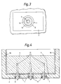
- FIGURE 2 shows a diagrammatic end cross-section of the part of the furnace with the refractory block as shown in Figure 1 of the drawings;
- FIGURE 3 shows a diagrammatic cross-section along the line X-X' of the part of the furnace with the refractory block as shown in Figures 1 and 2 of the drawings, and
- FIGURE 4 is a section through a glass melting furnace in accordance with the present invention.
- Now referring to Figures 1 to 2 of the accompanying drawing there is shown a
refractory block 1 mounted into thebottom wall 2 of a glass making furnace which is mounted upon a lattice network of supportingbeams 3. - The furnace contains a
volume 4 of molten glass, which is normally at a temperature in the region of 1000 to 1350oC. Consequently all the surfaces of the furnace exposed to the molten glass environment are provided with a layer or lining 5 of refractory material, for example fused cast Alumina-Zirconia-Silica. - The
refractory block 1 is located in a hole which is bored through thebottom wall 2 of the glass making furnace, and a second coaxial hole bored through the refractory lining, which is of narrower diameter than the hole bored in thebottom wall 2 and is coaxial therewith. - The
refractory block 1 is shaped and sized so that it forms a good contact with the surfaces of thebottom wall 2 and the refractory lining which surround therefractory block 1. Also the refractory block is provided with a central longitudinally extendingaxial throughbore 6 of constant diameter. - Consequently, the
refractory block 1 is of tubular construction having amain section 12 of a diameter substantially the same as that of the bored hole in the wall of the furnace into which it is located and asecond section 13 of a diameter substantially the same as that of the bored hole in the refractory lining. Now as a result of the difference in external diameters between themain section 12 and thesecond section 13 of the refractory block 1 ashelf 14 is formed in the refractory block. - A plug means 9 is located in one end of the
throughbore 6 of therefractory block 1 in order to prevent the passage of molten glass along thethroughbore 6 to the outside environment during the period prior to insertion of the ancillary equipment, for example an electrode heating device, into the furnace by means of thethroughbore 6. - Once located in the bored holes the
refractory block 1 is secured in position by means of asupport ring 8 and a supportingconstruction 7 which holds thesupport ring 8 and thereby therefractory block 1 in position. - Finally, a
keeper 10 including abar 11 normally connected to the lattice work 3 to mount the keeper in position, and an end section formed from refractory material, is inserted into thethroughbore 6 from the exterior to further ensure that molten glass does not pass down thethroughbore 6 prior to the insertion of ancillary equipment. - In order to mount a piece of ancillary equipment into the furnace by means of the throughbore in a located
refractory block 1, the following procedure is adopted: - The
keeper 10 is moved from thethroughbore 6; - the ancillary equipment, for example the electrode of the electrode heating means, is inserted into the
throughbore 6; - The ancillary equipment is pushed along the
throughbore 6 and into the molten glass within the glass making furnace; on its passage the ancillary equipment dislodges theplug 9 from its position; and - the ancillary equipment is secured into position and is connected up for operation.
- The
refractory block 1 is located into the wall of a furnace using the following procedure: - a first hole A is bored through the appropriate wall of the furnace but does not extend through the refractory lining of the furnace;
- a second hole B of narrower diameter is now bored, so that it is coaxial with the first hole A, through the refractory lining of the furnace;
- a
refractory block 1 with the plug means 9 in position in thethroughbore 6 is inserted into the first hole A and pushed into position with themain section 12 thereof located in the first hole A and thesecond section 13 located in the second hole B so that theshelf 14 abuts against the refractory lining of the furnace; - the
support ring 8 is inserted into the hole A so that it abuts the base of therefractory block 1; - the
support ring 8 and thereby therefractory block 1 are now secured into position using the supportingconstruction 7; and - the
keeper 10, or the ancillary equipment, is now located into thethroughbore 6 awaiting insertion of the ancillary equipment into the furance environment. - Figure 4 shows a glass melting furnace with side walls 15 having a refractory lining and a row of vertically extending
electrodes 17 each fitted through thethroughbore 6 of a respectiverefractory block 1 in thebottom wall 2 of the furnace. - The invention has been illustrated above by means of an example in which the ancillary equipment has been mounted into the furnace through the bottom wall. However, it will be well appreciated by those skilled in the art that the method of mounting ancillary equipment in accordance with the present invention is not limited to mounting through the bottom wall and may be used with respect to any one of the walls of the furnace. In alternative embodiments, the
throughbore 6 may be stepped or tapered.
Claims (14)
- A method of mounting a refractory block member (1) in a wall (2) of a glass melting furnace from the exterior of the furnace, the refractory block member being a mounting member adapted to receive ancillary equipment which may be inserted from the exterior of the furnace for use in the furnace environment, the method comprising: forming a partial distance through the wall of the furnace from the exterior thereof a first hole (A) of a first cross-sectional area; forming completely through the wall of the furnace from the exterior thereof, as an extension of the first hole, a second hole (B) of smaller cross-sectional area than the first hole, thereby forming a stepped opening through the wall of the furnace; and securing in said stepped opening a block member (1) having an inner portion (13) adapted to fit closely with the second hole and an outer portion (12) adapted to fit closely with the first hole, characterised in that a displaceable plug (9) is located at an inner end of a throughbore extending longitudinally through the refractory block member, the plug being displaceable from the inner end of the throughbore (6) by inserting a piece of ancillary equipment (17) therein from an outer end of the outer portion (12).
- A method as claimed in claim 1, characterised in that the first hole (A) and the second hole (B) are each circular in cross-section and coaxial with each other, and said inner and outer portions (13,12) of said block member (1) are of circular cross-section and of diameters which fit closely within said first and second holes respectively.
- A method as claimed in claim 1 or 2, in which the wall (2) of the furnace comprises an outer layer (2) and an inner refractory layer (5), the method being characterised in that the first hole (A) is formed entirely within the outer layer and in that the second hole (B) is formed through the inner refractory layer (5).
- A method as claimed in any preceeding claim, characterised in that the block member (1) comprises a unitary block with a step (14) adjacent a junction of the inner and outer portions, and by abutting the step of the block member against the step in the opening.
- A method as claimed in any preceding claim, characterised by mounting a piece of ancillary equipment (17) in the throughbore (6) by inserting the ancillary equipment (17) therein and displacing the plug (9) from the throughbore (6).
- A refractory mounting block member for mounting in a wall of a glass melting furnace from the exterior tnereof, said block being adapted to receive ancillary equipment which is inserted from the exterior of the furnace for use in the furnace environment, said block (1) having an outer portion (12) of circular cross-section adapted to fit a first hole (A) bored a partial distance through the wall (2) Of the furnace from the exterior thereof; an inner portion (13) of circular cross-section coaxial with the outer portion and of smaller diameter than the outer portion, said inner portion being adapted to fit a second hole (B) bored completely through the wall of the furnace from the exterior thereof, a passageway (6) entirely through both the outer and inner portions, characterised by a removable plug member (9) for mounting in said passageway (6) at an inner end of the outer portion, said plug member (9) including a shaft member for location in said passageway and a cap member attached to the shaft member for abutment against an inner face of the inner portion (13) to prevent movement of the plug member towards the outer portion (12), the plug member being slidable in the passageway (6) so that the plug member may be displaced by insertion of an ancillary device (17) through the passageway of the refractory block.
- A block member as claimed in claim 6, characterised in that the passageway (6) extends centrally through the block member (1).
- A block member as claimed in claim 7, characterised in that the central passageway (6) is of constant diameter along its length.
- A block member as claimed in claim 7, characterised in that the central passageway (6) is stepped.
- A block member as claimed in claim 7, characterised in that the central passageway (6) is tapered.
- A glass melting furnace having side and bottom walls (2,16) formed of refractory material, a first hole (A) of a first cross-sectional area formed a partial distance through a wall (2) of the furnace from the exterior thereof; a second hole (B) of a smaller cross-sectional area than the first hole formed completely through the wall of the furnace from the exterior thereof, as a co-axial extension of the first hole, the first and second holes together comprising a stepped opening through the walls of the furnace; a refractory block member (1) having a longitudinal bore (6) entirely through the block member adapted to receive ancillary equipment (17) inserted from the exterior of the furnace for use in the furnace environment, said block member having an inner portion (13) fitted closely with the second hole (B) and an outer portion (12) fitted closely with the first hole (A), characterised by a removable plug member (9) for fitting in said longitudinal bore against an inner end of the inner portion (13) and displaceable by insertion of ancillary equipment for use in the furnace.
- A glass melting furnace as claimed in claim 11, in which the wall thereof comprises an outer layer (2) and an inner refractory layer (5), the furnace being characterised in that the first hole (A) is formed in the outer layer (2) and in that the second hole (B) extends through the inner refractory layer (5).
- A glass melting furnace as claimed in claim 11 or 12, characterized in that the inner portion (13) and the outer portion (12) of the block member together form a unitary stepped block (1).
- A glass melting furnace as claimed in any of claims 11 to 13 characterized in that the first hole (A) and the second hole (B) are each circular in cross-section and in that the first and second holes are each bored into a bottom wall (2) of the furnace from the exterior thereof so that the block member extends upwardly with said inner portion above said outer portion.
Applications Claiming Priority (2)
| Application Number | Priority Date | Filing Date | Title |
|---|---|---|---|
| GB9104445 | 1991-03-02 | ||
| GB919104445A GB9104445D0 (en) | 1991-03-02 | 1991-03-02 | Method of mounting ancillary equipment to a furnace |
Publications (2)
| Publication Number | Publication Date |
|---|---|
| EP0502650A1 EP0502650A1 (en) | 1992-09-09 |
| EP0502650B1 true EP0502650B1 (en) | 1994-11-02 |
Family
ID=10690897
Family Applications (1)
| Application Number | Title | Priority Date | Filing Date |
|---|---|---|---|
| EP92301671A Expired - Lifetime EP0502650B1 (en) | 1991-03-02 | 1992-02-27 | Method and apparatus for mounting ancillary equipment to a furnace |
Country Status (16)
| Country | Link |
|---|---|
| US (1) | US5236490A (en) |
| EP (1) | EP0502650B1 (en) |
| JP (1) | JPH05345617A (en) |
| KR (1) | KR920017959A (en) |
| AU (1) | AU655228B2 (en) |
| BR (1) | BR9200579A (en) |
| CA (1) | CA2061473A1 (en) |
| CZ (1) | CZ284260B6 (en) |
| DE (1) | DE69200597T2 (en) |
| ES (1) | ES2066557T3 (en) |
| GB (1) | GB9104445D0 (en) |
| MX (1) | MX174513B (en) |
| RU (1) | RU2081066C1 (en) |
| TR (1) | TR27998A (en) |
| TW (1) | TW221410B (en) |
| ZA (1) | ZA921248B (en) |
Families Citing this family (4)
| Publication number | Priority date | Publication date | Assignee | Title |
|---|---|---|---|---|
| US20020116951A1 (en) * | 2001-02-27 | 2002-08-29 | Dunifon Thomas A. | Conformally heated male mold |
| ES2293770B1 (en) * | 2005-05-04 | 2009-02-01 | Cristalerias De Mataro S.C.O.C.L. | PERFECTED GLASS FUSION OVEN. |
| CN105110633A (en) * | 2008-12-18 | 2015-12-02 | 圣戈本陶瓷及塑料股份有限公司 | Bushing block |
| CN113048781A (en) * | 2021-03-09 | 2021-06-29 | 王建生 | Vertical sintering furnace convenient to clean |
Family Cites Families (15)
| Publication number | Priority date | Publication date | Assignee | Title |
|---|---|---|---|---|
| FR965134A (en) * | 1950-09-04 | |||
| US3015190A (en) * | 1952-10-13 | 1962-01-02 | Cie De Saint Gobain Soc | Apparatus and method for circulating molten glass |
| US3422206A (en) * | 1965-04-07 | 1969-01-14 | Union Carbide Corp | Method and apparatus for melting metal in an electric furnace |
| US3391236A (en) * | 1965-07-06 | 1968-07-02 | Emhart Corp | Electrode holder for glass melting furnace |
| NL167201C (en) * | 1970-04-28 | 1981-11-16 | Koninklijke Hoogovens En Staal | METHOD AND APPARATUS FOR MAINTAINING THE TAP HOLE OF A STEEL CONVERTER |
| BE792996A (en) * | 1972-01-03 | 1973-04-16 | Uss Eng & Consult | PROCESS FOR INSTALLING A REMOVABLE BOTTOM, INCLUDING TUBES, IN A REFINING TANK FOR A MELTED METAL |
| CA969776A (en) * | 1972-03-06 | 1975-06-24 | Jacques Antoine | Device for measuring the temperature in a furnace |
| US3811859A (en) * | 1972-06-09 | 1974-05-21 | Ppg Industries Inc | Process and apparatus for electrolytically generating stirring bubbles in a glass melt |
| US3938791A (en) * | 1972-07-31 | 1976-02-17 | Centro Sperimentale Metallurgico S.P.A. | Device for plugging tap-holes of reactors for metallurgical processes |
| US3777040A (en) * | 1973-04-25 | 1973-12-04 | Toledo Eng Co Inc | Protection of glass melting furnace electrode |
| US4198279A (en) * | 1977-11-10 | 1980-04-15 | Corning Glass Works | Oxygen sensor mounting structure |
| US4215461A (en) * | 1979-01-31 | 1980-08-05 | Ppg Industries, Inc. | Method for inserting electrodes into glass melting tanks |
| DE3339514A1 (en) * | 1983-10-28 | 1985-05-09 | Mannesmann AG, 4000 Düsseldorf | ELECTRODE ARRANGEMENT IN WARM-TYPE VESSELS |
| DE3529365A1 (en) * | 1985-08-16 | 1987-02-19 | Glashuettentechnik Grob Gmbh | Holder for an electrode of an electrically heated glass melting furnace |
| US5151918A (en) * | 1990-08-28 | 1992-09-29 | Argent Ronald D | Electrode blocks and block assemblies |
-
1991
- 1991-03-02 GB GB919104445A patent/GB9104445D0/en active Pending
-
1992
- 1992-02-19 CA CA002061473A patent/CA2061473A1/en not_active Abandoned
- 1992-02-20 ZA ZA921248A patent/ZA921248B/en unknown
- 1992-02-20 TW TW081101262A patent/TW221410B/zh active
- 1992-02-21 US US07/838,884 patent/US5236490A/en not_active Expired - Fee Related
- 1992-02-21 BR BR929200579A patent/BR9200579A/en not_active Application Discontinuation
- 1992-02-24 AU AU11188/92A patent/AU655228B2/en not_active Ceased
- 1992-02-27 ES ES92301671T patent/ES2066557T3/en not_active Expired - Lifetime
- 1992-02-27 DE DE69200597T patent/DE69200597T2/en not_active Expired - Fee Related
- 1992-02-27 EP EP92301671A patent/EP0502650B1/en not_active Expired - Lifetime
- 1992-02-28 JP JP4043344A patent/JPH05345617A/en active Pending
- 1992-02-28 MX MX9200858A patent/MX174513B/en unknown
- 1992-03-02 KR KR1019920003433A patent/KR920017959A/en not_active Application Discontinuation
- 1992-03-02 CZ CS92611A patent/CZ284260B6/en unknown
- 1992-03-02 RU SU925011045A patent/RU2081066C1/en active
- 1992-03-02 TR TR00196/92A patent/TR27998A/en unknown
Also Published As
| Publication number | Publication date |
|---|---|
| US5236490A (en) | 1993-08-17 |
| ZA921248B (en) | 1992-11-25 |
| EP0502650A1 (en) | 1992-09-09 |
| AU655228B2 (en) | 1994-12-08 |
| CZ284260B6 (en) | 1998-10-14 |
| KR920017959A (en) | 1992-10-21 |
| BR9200579A (en) | 1992-11-10 |
| TR27998A (en) | 1995-11-13 |
| GB9104445D0 (en) | 1991-04-17 |
| CS61192A3 (en) | 1992-10-14 |
| CA2061473A1 (en) | 1992-09-03 |
| TW221410B (en) | 1994-03-01 |
| MX9200858A (en) | 1992-09-01 |
| ES2066557T3 (en) | 1995-03-01 |
| MX174513B (en) | 1994-05-20 |
| RU2081066C1 (en) | 1997-06-10 |
| DE69200597D1 (en) | 1994-12-08 |
| DE69200597T2 (en) | 1995-06-08 |
| AU1118892A (en) | 1992-09-03 |
| JPH05345617A (en) | 1993-12-27 |
Similar Documents
| Publication | Publication Date | Title |
|---|---|---|
| US6178777B1 (en) | Side-discharge melter for use in the manufacture of fiberglass, and corresponding method | |
| KR101580005B1 (en) | Method for exchangeably fastening a refractory purge plug or sleeve and a container for molten metal | |
| MY129331A (en) | Process of installing roof mounted oxygen-fuel burners in a glass melting furnace | |
| EP0502650B1 (en) | Method and apparatus for mounting ancillary equipment to a furnace | |
| US2817695A (en) | Electric furnace and electrode structures for kaolin melting | |
| US3495815A (en) | Outside change tuyere | |
| EP3080536B1 (en) | Tap-hole refurbishing | |
| US5865617A (en) | Replaceable nozzle for high temperature reactors having a fire-resistant lining | |
| US4424027A (en) | Insulating tile for application to water cooled pipes and method for applying same to pipes | |
| US6220373B1 (en) | Drill rod with axial air passageway and method of making same | |
| JP3860624B2 (en) | Method for converting furnace to oxy-fuel furnace and burner block assembly while operating the furnace | |
| CZ334395A3 (en) | Electrode for tank furnaces with rod-type electrode | |
| JP3105166B2 (en) | Skid button device | |
| US2836865A (en) | Crucible pour mechanism | |
| US7564007B2 (en) | Kiln removable ceramic element holder | |
| US5921333A (en) | Casting having in-situ cast inserts and method of manufacturing | |
| JPH11189815A (en) | Working method of exchanging of stave in blast furnace | |
| US4398703A (en) | Tuyeres with heat pipes and method of manufacturing | |
| EP0819888B1 (en) | Method of converting a furnace from air-fuel burners to oxygen-fuel burners and oxy-fuel burner block assembly | |
| JPH0447Y2 (en) | ||
| JPS624808A (en) | Method and apparatus for repairing trough for high-temperature melt | |
| KR200271048Y1 (en) | Device for insulating submerged nozzle of steelmaking tundish | |
| GB2074707A (en) | Tuyeres for blast furnaces | |
| CA1127992A (en) | Lining for protecting coke-oven-chamber doors from the heat inside the oven | |
| KR20070073420A (en) | Bubbling plug having sleeve block |
Legal Events
| Date | Code | Title | Description |
|---|---|---|---|
| PUAI | Public reference made under article 153(3) epc to a published international application that has entered the european phase |
Free format text: ORIGINAL CODE: 0009012 |
|
| AK | Designated contracting states |
Kind code of ref document: A1 Designated state(s): BE DE ES FR GB IT LU |
|
| 17P | Request for examination filed |
Effective date: 19930304 |
|
| 17Q | First examination report despatched |
Effective date: 19930406 |
|
| GRAA | (expected) grant |
Free format text: ORIGINAL CODE: 0009210 |
|
| AK | Designated contracting states |
Kind code of ref document: B1 Designated state(s): BE DE ES FR GB IT LU |
|
| REF | Corresponds to: |
Ref document number: 69200597 Country of ref document: DE Date of ref document: 19941208 |
|
| ET | Fr: translation filed | ||
| ITF | It: translation for a ep patent filed | ||
| REG | Reference to a national code |
Ref country code: ES Ref legal event code: FG2A Ref document number: 2066557 Country of ref document: ES Kind code of ref document: T3 |
|
| PLBE | No opposition filed within time limit |
Free format text: ORIGINAL CODE: 0009261 |
|
| STAA | Information on the status of an ep patent application or granted ep patent |
Free format text: STATUS: NO OPPOSITION FILED WITHIN TIME LIMIT |
|
| 26N | No opposition filed | ||
| PGFP | Annual fee paid to national office [announced via postgrant information from national office to epo] |
Ref country code: LU Payment date: 19971216 Year of fee payment: 7 |
|
| PGFP | Annual fee paid to national office [announced via postgrant information from national office to epo] |
Ref country code: FR Payment date: 19980210 Year of fee payment: 7 |
|
| PGFP | Annual fee paid to national office [announced via postgrant information from national office to epo] |
Ref country code: GB Payment date: 19980218 Year of fee payment: 7 |
|
| PGFP | Annual fee paid to national office [announced via postgrant information from national office to epo] |
Ref country code: ES Payment date: 19980226 Year of fee payment: 7 |
|
| PGFP | Annual fee paid to national office [announced via postgrant information from national office to epo] |
Ref country code: DE Payment date: 19980306 Year of fee payment: 7 |
|
| PGFP | Annual fee paid to national office [announced via postgrant information from national office to epo] |
Ref country code: BE Payment date: 19980417 Year of fee payment: 7 |
|
| PG25 | Lapsed in a contracting state [announced via postgrant information from national office to epo] |
Ref country code: LU Free format text: LAPSE BECAUSE OF NON-PAYMENT OF DUE FEES Effective date: 19990227 Ref country code: GB Free format text: LAPSE BECAUSE OF NON-PAYMENT OF DUE FEES Effective date: 19990227 |
|
| PG25 | Lapsed in a contracting state [announced via postgrant information from national office to epo] |
Ref country code: BE Free format text: LAPSE BECAUSE OF NON-PAYMENT OF DUE FEES Effective date: 19990228 |
|
| PG25 | Lapsed in a contracting state [announced via postgrant information from national office to epo] |
Ref country code: ES Free format text: LAPSE BECAUSE OF NON-PAYMENT OF DUE FEES Effective date: 19990301 |
|
| BERE | Be: lapsed |
Owner name: PILKINGTON GLASS LTD Effective date: 19990228 |
|
| GBPC | Gb: european patent ceased through non-payment of renewal fee |
Effective date: 19990227 |
|
| PG25 | Lapsed in a contracting state [announced via postgrant information from national office to epo] |
Ref country code: FR Free format text: LAPSE BECAUSE OF NON-PAYMENT OF DUE FEES Effective date: 19991029 |
|
| REG | Reference to a national code |
Ref country code: FR Ref legal event code: ST |
|
| PG25 | Lapsed in a contracting state [announced via postgrant information from national office to epo] |
Ref country code: DE Free format text: LAPSE BECAUSE OF NON-PAYMENT OF DUE FEES Effective date: 20000101 |
|
| REG | Reference to a national code |
Ref country code: ES Ref legal event code: FD2A Effective date: 20010503 |
|
| PG25 | Lapsed in a contracting state [announced via postgrant information from national office to epo] |
Ref country code: IT Free format text: LAPSE BECAUSE OF NON-PAYMENT OF DUE FEES Effective date: 20050227 |