EP0502463B1 - Recording or reproducing apparatus and head supporting device - Google Patents
Recording or reproducing apparatus and head supporting device Download PDFInfo
- Publication number
- EP0502463B1 EP0502463B1 EP92103578A EP92103578A EP0502463B1 EP 0502463 B1 EP0502463 B1 EP 0502463B1 EP 92103578 A EP92103578 A EP 92103578A EP 92103578 A EP92103578 A EP 92103578A EP 0502463 B1 EP0502463 B1 EP 0502463B1
- Authority
- EP
- European Patent Office
- Prior art keywords
- sheet
- head
- pad
- recording medium
- recording
- Prior art date
- Legal status (The legal status is an assumption and is not a legal conclusion. Google has not performed a legal analysis and makes no representation as to the accuracy of the status listed.)
- Expired - Lifetime
Links
Images


Classifications
-
- G—PHYSICS
- G11—INFORMATION STORAGE
- G11B—INFORMATION STORAGE BASED ON RELATIVE MOVEMENT BETWEEN RECORD CARRIER AND TRANSDUCER
- G11B17/00—Guiding record carriers not specifically of filamentary or web form, or of supports therefor
- G11B17/32—Maintaining desired spacing between record carrier and head, e.g. by fluid-dynamic spacing
Definitions
- This invention relates to a head supporting device according to the precharacterizing part of claim 1.
- the invention further relates to an apparatus for recording or reproducing information including such a head supporting device.
- Recording or reproducing apparatuses of the kind arranged to perform recording or reproduction on or from a sheet-shaped recording medium such as a flexible magnetic disc or the like have been known.
- the apparatus of this kind uses a head supporting device (hereinafter referred to as a pad) which is arranged to generate fluidic pressure through the travel of the magnetic sheet to push the magnetic sheet against the head for stable contact of the magnetic sheet with the magnetic head while the sheet is traveling.
- a head supporting device hereinafter referred to as a pad
- FIG. 1(a) and 1(b) of the accompanying drawings A similar head supporting device or pad is shown in Figs. 1(a) and 1(b) of the accompanying drawings.
- the pad 100 is disposed around a magnetic head 4.
- a flat part 104 of the pad 100 has a slot 108 arranged in its middle part on one side of the pad 100 facing a magnetic sheet 3 (see Fig. 2) to allow the magnetic head 4 to pass therethrough.
- Projecting strip parts 101 and 103 are formed in concentric circular shapes to protrude to a given height from the flat part 104 and are spaced at a given distance through an annular groove part 102 around the periphery of the flat part 104.
- the projecting strip parts 101 and 103 are provided with cutout parts 105 and 106. These cutout portions 105 and 106 are arranged on a downstream side D of the movement of the magnetic sheet 3, in the direction of arrow A, to eject an air stream generated by the rotation of the magnetic sheet 3 in such a way as to control negative pressure brought forth by the pad 100.
- Fig. 8(b) shows the results of fluidic analysis of the distribution of pressure between the pad 100 and the magnetic sheet 3.
- the distribution of pressure is taken along a line B-B shown in Fig. 1(a).
- the points P1 to P8 of Fig. 8(b) correspond to points P1 to P8 of Fig. 1(a).
- the planar distribution of a contact force between the pad 100 and the magnetic sheet 3 is as shown in Fig. 4(b).
- the upper faces 101a and 103a of the projecting strip parts 101 and 103 are formed approximately on the same plane. Therefore, when the magnetic sheet 3 is sucked by the pad 100 into contact with the head 4, the distribution of the contact force which is as shown in Fig. 4(b) causes the magnetic sheet 3 to come into contact with the sliding-contact faces 101a and 103a of the pad 100 in a greatly partial manner. The partial contact then tends to damage the magnetic sheet 3 or to cause fluctuations in the negative pressure on a spindle motor, uneven rotation, jitters and so on.
- the force of sucking is weak on the downstream side D of the head 4 in the rotating direction of the magnetic sheet 3 to cause the deformation of the magnetic sheet 3 to become asymmetric relative to the head 4 as shown in Fig. 5(b).
- the head 4 comes into strong contact with the magnetic sheet 3 on its upstream side U to result in a partial abrasion of the head 4.
- the conventional device has presented another problem: Since the magnetic sheet 3 is sucked by the negative pressure which is brought forth by the groove part 102, the magnetic sheet 3 is deformed, considering it microscopically, at the projecting strip parts 101 and 103 as shown in Fig. 9(b). The magnetic sheet 3 thus comes into contact with the edges 101b and 103b of the projecting strip parts 101 and 103. This condition not only tends to cause the magnetic sheet 3 to be damaged by the pad 100 but also might hinder recording or reproduction.
- Figs. 1(a) and 1(b) are a plan view and a sectional view showing by way of example the conventional pad.
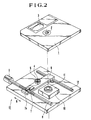
- Fig. 2 is an oblique view showing a disc (or sheet) driving deice to which this invention is applied as an embodiment thereof.
- Fig. 3 is a sectional view showing an embodiment of the invention.
- Figs. 4(a) and 4(b) show contact force distribution between a sheet-shaped recording medium and a pad, Fig. 4(a) showing the contact force distribution obtained by the embodiment of the invention and Fig. 4(b) showing the contact force distribution obtained by the conventional pad.
- Figs. 4(a) and 4(b) show contact force distribution between a sheet-shaped recording medium and a pad.
- FIG. 5(a) and 5(b) show the deformation of a sheet-shaped magnetic recording medium taking place when the sheet-shaped recording medium is sucked, Fig. 5(a) showing a deformation caused by the embodiment and Fig. 5(b) showing the deformation caused by the conventional device.
- Figs. 6(a) and 6(b) are a plan view and a sectional view showing another embodiment of the invention.
- Figs. 8(a) and 8(b) show distribution of pressure obtained between the sheet and the pad, Fig. 8(a) showing the pressure distribution obtained by the embodiment and Fig. 8(b) showing the pressure distribution obtained by the conventional device.
- Figs. 9(a) and 9(b) show sheet-sucking states obtained at projecting strip parts of the pads, Fig.
- Fig. 10 shows the distribution of a contact force obtained by the embodiment between the projecting strip parts of the pad and the sheet-shaped magnetic recording medium.
- Fig. 2 shows in an oblique view the recording or reproducing apparatus embodying this invention.
- a magnetic sheet 3 for recording (hereinafter referred to as the sheet) is rotatably stowed in a disc jacket 1.
- the sheet 3 has a center core 2 arranged in the middle part of the sheet 3 to be securely set on a spindle mounted on the rotation shaft of a spindle motor 10.
- a disc driving device 13 is arranged to drive and rotate the sheet 3 disposed within the disc jacket 1.
- the disc driving device 13 is provided with a magnetic recording or reproducing head 4 (hereinafter referred to as the head) and a pad 5 which is arranged around the head 4 to generate a sucking force (negative pressure) by the rotation of the sheet 3, as will be described in detail later.
- the head 4 and the pad 5 are secured by an adhesive to a head carriage 6 which is arranged to move the head 4.
- the head carriage 6 has an engaging part 7a of an elastic member 7 secured to one end thereof and is engaged by the engaging part 7a with a head moving mechanism which consists of a stepping motor 9 and a lead screw 8.
- the other end of the head carriage 6 is carried by a guide bar 12 in such a way as to be axially slidable on the guide bar 12.
- the head carriage 6 is thus arranged to be radially moved over the sheet 3 in the direction of arrow B to a given extent at a time.
- parts supporting the motor 9, the lead screw 8 and the guide bar 12 are omitted from the illustration.
- a spindle motor 10 is arranged to rotate the sheet 3 and has a chucking part 11 which is arranged to hold the center core 2 of the sheet 3.
- the sheet 3 is held by the chucking part 11 in such a way as to be freely detachable when the disc jacket 1 is demounted from the apparatus by a known means.
- the sheet 3 is rotated by the motor 10, the sheet 3 is sucked toward the pad 5 by a fluidic action of an air stream taking place between the sheet 3 and the pad 5. With the sheet 3 thus sucked, the sheet 3 comes into pressed contact with the head 4 to give an adequate touch of the head 4 on the sheet 3.
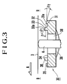
- Fig. 3 is a sectional view showing by way of example a pad arranged in a device in accordance with this invention.
- the pad 30 is in a circular disc-like shape.
- the pad 30 comprises a first projecting strip part 33, a second projecting strip part 31, an annular groove part 32, a flat part 34 and a head mounting hole 38 which is formed in the flat part 34. These parts are arranged to surround the head 4. Cutout parts 35 and 36 are formed on the downstream side D of the pad 30.
- the head 4 is secured by means of an adhesive 39 to the inside of the head mounting hole 38 with the tip of the head 4 protruding further than the upper end of the projecting strip part 33 by scores of ⁇ m.
- the pad 30 is thus arranged to prevent any leak of air to ensure a stable state of negative pressure.
- the upper end sides of the second and first projecting strip parts 31 and 33 are formed aslant to have angles of inclination ⁇ 2 and ⁇ 1, respectively, as shown in Fig. 3.
- the sheet 3 is deformed in a natural manner along the sliding-contact faces 31a and 33a of the projecting strip parts 31 and 33.
- the possibility of the partial contact which has resulted from the conventional arrangement thus can be minimized by the embodiment of this invention.
- the embodiment gives a greater positive pressure than the conventional device on the upstream side U of the pad 30, so that the contact force of the sheet 3 on the pad 30 is lowered accordingly.
- the arrangement to form the sliding-contact faces 31a and 33a of the projecting strip parts 31 and 33 in a tapered shape weakens the positive pressure between the sheet 3 and the sliding-contact faces 31a and 33a of the pad 30.
- the thus weakened positive pressure allows the sheet 3 to be sufficiently sucked toward the pad 30 by the negative pressure developed at the groove part 32 and the flat part 34.
- the sheet 3 is deformed symmetrically with respect to the center of the head 4 when the gap part of the head 4 comes into contact with the sheet 3.
- the symmetric contact not only improves the head touch characteristic but also reduces the partial abrasion of the head 4.
- Figs. 4(a), 4(b), 5(a) and 5(b) show the results of simulation tests of the above-stated concept made in respect to fluidics and strength of materials.
- Figs. 4(a) and 4(b) show the distribution of the contact force between the sheet 3 and the pad 30.
- Figs. 5(a) and 5(b) are enlarged illustrations of the deformation in the deforming direction of the sheet 3.
- Figs. 4(b) and 5(b) show the results of simulation made for the conventional device
- the pad 100 strongly touches the radially outer and inner sides of the sheet 3 (upper and lower sides of the figure on the outer side of the projecting strip part 103. It has been ascertained through tests that the probability of occurrence of damages at the above-stated parts of the sheet 3 is high.
- the contact of the projecting strip part 33 with the sheet 3 is much more moderate. Meanwhile, the contact force is strong on the downstream side D on the inner side of the projecting strip part 31 and also is strong on the radially inner side of the sheet 3 (lower side of the figure).
- This result suggests that a better result is obtainable by setting the angle of inclination ⁇ 2 of the projecting strip part 31 at a smaller angle than the angle of inclination ⁇ 1 of the projecting strip part 33.
- the angles of inclination ⁇ 1 and ⁇ 2 should be in the following relation: ⁇ 1 ⁇ ⁇ 2 > 0 or ⁇ 1 > ⁇ 2 ⁇ 0
- the sheet 3 is apt to be damaged at its parts where the contact forces of the projecting strip parts 31 and 33 are strong. Therefore, the edges of the projecting strip parts 31 and 33 are preferably chamfered to a very small extent (scores of ⁇ m). These edges can be chamfered as desired by polishing the sliding-contact faces of the pad 30 through a flexible matter such as leather.
- the sheet 3 strongly touches the head 4 at a point on the upstream side U relative to the head 4. Hence, partial abrasion (wear) and an inadequate head touch tend to occur around this point. Whereas, in the case of Fig. 4(a), the sheet 3 strongly touches the central part of the head 4. In this case, therefore, the head 4 evenly wears away relative to the gap part of the head 4 to ensure an adequate head touch characteristic.
- the sheet 3 is away from the sliding-contact face 103a of the pad 100 on the downstream side D, as shown in Fig. 5(b).
- the deformation of the sheet 3 becomes asymmetric to cause the partial abrasion of the head 4.
- the sheet 3 is deformed nearly symmetrically relative to the head 4 on both the upstream and downstream sides U and D of the pad 30, as shown in Fig. 5(a). Therefore, the head 4 can be prevented from partially wearing.
- angles of inclination ⁇ 2 and ⁇ 1 of the sliding-contact faces 31a and 33a are arranged to be equal to each other. However, these angles may be arranged to be different from each other according to the distribution of pressure.
- the sliding-contact faces 33a and 31a of the first and second projecting strip parts 33 and 31 of the pad 30 are formed to be slanting upward toward the head 4. Therefore, the local contact forces of the sheet 3 on the head 4 and the pad 30 can be lowered and applied to their points which are symmetrically located. Therefore, the sheet 3 can be prevented from being damaged; jitters can be lessened; and the head 4 can be saved from partial abrasion.
- the arrangement of the embodiment thus greatly enhances the reliability and the durability of the apparatus.
- such parts of the pad 30 that tend to damage the sheet 3, i.e., the edges of the projecting strip parts 31 and 33, are slightly chamfered for preventing the sheet 3 from being damaged.
- this purpose is attained by more positively defining the edge shapes of the projecting strip parts as described below:
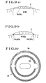
- Figs. 6(a) and 6(b) show by way of example how the shape of the ridgelines of the projecting strip parts of the pad is defined.
- Fig. 6(a) shows the example in a plan view and Fig. 6(b) in a sectional view as taken along a center line of Fig. 6(a).
- the pad 60 is disposed around the magnetic head 4 and has a flat part 64 formed on one side of the pad 60 facing the magnetic sheet 3 (see Fig. 2).
- a slot (or hole) 68 is arranged in the middle part of the flat part 64 to allow the head 4 to be inserted therethrough.
- Concentric circular projecting strip parts 61 and 63 which protrude to a given height from the flat part 64 are spaced a given distance across an annular groove part 62.
- Cutout parts 65 and 66 which are arranged to eject an air stream generated by the rotation of the sheet 3 for controlling negative pressure developed by the pad 60 are formed at parts located on the downstream side D relative to the moving direction of the sheet 3 indicated by an arrow A.
- another cutout part 67 is formed in the projecting strip part 63 by cutting the projecting strip part 63 from its upper surface side down to a part which is at the same height as the flat part 64.
- Fig. 7 shows the sectional shape of the sliding-contact faces of the projecting strip parts 61 and 63 of the pad 60 which come into sliding contact with the sheet 3.
- This shape consists of a straight line and a plurality of circular arcs.
- the straight line part is located in the middle part "a".
- the both ends of the straight line part is moderately connected to circular arcs of a radius R1.
- Each of the arcs is further connected to an arc of a radius R2 smaller than R1.
- R1 : R2 10 : 1.
- the middle straight line part "a" may be replaced with an arc having a much greater radius than the radius R1 or R2.
- FIG. 8(a) shows the results of a fluidic analysis of pressure distribution thus obtained between the pad 60 and the sheet 3.
- the pressure distribution shown in Fig. 8(a) is obtained along a straight line A-A shown in Fig. 6(a).
- Points P1 to P8 shown in Fig. 8(a) correspond to points P1 to P8 shown in Fig. 6(a).
- Fig. 10 shows the results of an analysis of the state of contact of the sheet 3 with the whole pad 60.
- the sheet 3 is almost evenly touching the whole sliding-contact faces 61a and 63a of the projecting strip parts 61 and 63.
- each of the projecting strip parts 61 and 63 of the pad 60 consists of a nearly straight line part which is located on the side facing the sheet 3; and a plurality of arcs which continue from both ends of the nearly straight line part. Further, each of these arcs is formed to be consisting of a first arc which is of a radius R1 and continues from the nearly straight line part; and a second arc which is of a radius R2 and continues from the first arc.
- the radius R1 is arranged to be larger than the radius R2. This shape effectively reduces a sliding-contact resistance between the sheet 3 and the pad 60, so that a load on the spindle motor can be lessened and the motor can be prevented from unevenly rotating.
- the recording medium is not damaged; and an adequate head touch is obtainable. Therefore, the reliability of the recording or reproducing apparatus can be enhanced and energy can be saved.
- This embodiment has been described as being arranged to have the inner projecting strip part 63 and the outer projecting strip part 61 on one and the same plane for the sake of facilitating the description. However, a synergetic effect is attained by the combination of the arrangement of this embodiment and that of the embodiment first described in the foregoing to give a still better recording or reproducing apparatus.
- the head supporting device is arranged to surrounded a head, to include a first projecting strip part which protrudes on one side of the device facing a sheet-shaped recording medium and a second projecting strip part which is formed on the outer side of the first projecting strip part with a spacing part interposed between the first and second projecting strip parts and to suck the recording medium with negative pressure, wherein the sliding-contact faces of the first and second projecting strip parts -are formed to be slanting upward toward the head, and a sectional shape of each of the projecting strip parts is composed of an approximately straight line which is on the recording-medium-facing side and a plurality of arcs which continue respectively from the two ends of the approximately straight line.
Landscapes
- Adjustment Of The Magnetic Head Position Track Following On Tapes (AREA)
- Supporting Of Heads In Record-Carrier Devices (AREA)
Description
- This invention relates to a head supporting device according to the precharacterizing part of
claim 1. The invention further relates to an apparatus for recording or reproducing information including such a head supporting device. - Recording or reproducing apparatuses of the kind arranged to perform recording or reproduction on or from a sheet-shaped recording medium such as a flexible magnetic disc or the like have been known.
- The apparatus of this kind uses a head supporting device (hereinafter referred to as a pad) which is arranged to generate fluidic pressure through the travel of the magnetic sheet to push the magnetic sheet against the head for stable contact of the magnetic sheet with the magnetic head while the sheet is traveling.
- According to document EP 0 333 431 A3 there is disclosed a generic head supporting device. A similar head supporting device or pad is shown in Figs. 1(a) and 1(b) of the accompanying drawings. Referring to these figures, the
pad 100 is disposed around amagnetic head 4. Aflat part 104 of thepad 100 has aslot 108 arranged in its middle part on one side of thepad 100 facing a magnetic sheet 3 (see Fig. 2) to allow themagnetic head 4 to pass therethrough.Projecting strip parts flat part 104 and are spaced at a given distance through anannular groove part 102 around the periphery of theflat part 104. The projectingstrip parts cutout parts cutout portions magnetic sheet 3, in the direction of arrow A, to eject an air stream generated by the rotation of themagnetic sheet 3 in such a way as to control negative pressure brought forth by thepad 100. - The sheet sliding-contact faces 101a and 103a of the projecting
strip parts pad 100 are in a flat shape. With thepad 100 disposed around themagnetic head 4 in the above-stated manner, when themagnetic sheet 3 is caused to rotate, a stream of air takes place between thepad 100 and themagnetic sheet 3 to bring forth a negative pressure which sucks themagnetic sheet 3. Fig. 8(b) shows the results of fluidic analysis of the distribution of pressure between thepad 100 and themagnetic sheet 3. In the case of Fig. 8(b), the distribution of pressure is taken along a line B-B shown in Fig. 1(a). The points P1 to P8 of Fig. 8(b) correspond to points P1 to P8 of Fig. 1(a). Further, the planar distribution of a contact force between thepad 100 and themagnetic sheet 3 is as shown in Fig. 4(b). - In the case of the conventional device described above, the
upper faces strip parts magnetic sheet 3 is sucked by thepad 100 into contact with thehead 4, the distribution of the contact force which is as shown in Fig. 4(b) causes themagnetic sheet 3 to come into contact with the sliding-contact faces pad 100 in a greatly partial manner. The partial contact then tends to damage themagnetic sheet 3 or to cause fluctuations in the negative pressure on a spindle motor, uneven rotation, jitters and so on. - Further, macroscopically considered, the force of sucking is weak on the downstream side D of the
head 4 in the rotating direction of themagnetic sheet 3 to cause the deformation of themagnetic sheet 3 to become asymmetric relative to thehead 4 as shown in Fig. 5(b). Under such a condition, thehead 4 comes into strong contact with themagnetic sheet 3 on its upstream side U to result in a partial abrasion of thehead 4. - The conventional device has presented another problem: Since the
magnetic sheet 3 is sucked by the negative pressure which is brought forth by thegroove part 102, themagnetic sheet 3 is deformed, considering it microscopically, at the projectingstrip parts magnetic sheet 3 thus comes into contact with theedges strip parts magnetic sheet 3 to be damaged by thepad 100 but also might hinder recording or reproduction. - It is an object of this invention to provide a recording or reproducing apparatus or a head supporting device which is arranged to adequately bring a magnetic head into contact with a sheet-shaped magnetic recording medium without damaging the recording medium by lessening a sliding contact resistance between them.
- This object is achieved by means of the combination of the features defined in
claim 1. Preferable embodiments of the invention are specified inclaims 2 to 5. - The above and other objects and features of the invention will become apparent from the following detailed description of embodiments thereof taken in conjunction with the accompanying drawings.
- Figs. 1(a) and 1(b) are a plan view and a sectional view showing by way of example the conventional pad. Fig. 2 is an oblique view showing a disc (or sheet) driving deice to which this invention is applied as an embodiment thereof. Fig. 3 is a sectional view showing an embodiment of the invention. Figs. 4(a) and 4(b) show contact force distribution between a sheet-shaped recording medium and a pad, Fig. 4(a) showing the contact force distribution obtained by the embodiment of the invention and Fig. 4(b) showing the contact force distribution obtained by the conventional pad. Figs. 5(a) and 5(b) show the deformation of a sheet-shaped magnetic recording medium taking place when the sheet-shaped recording medium is sucked, Fig. 5(a) showing a deformation caused by the embodiment and Fig. 5(b) showing the deformation caused by the conventional device. Figs. 6(a) and 6(b) are a plan view and a sectional view showing another embodiment of the invention. Figs. 8(a) and 8(b) show distribution of pressure obtained between the sheet and the pad, Fig. 8(a) showing the pressure distribution obtained by the embodiment and Fig. 8(b) showing the pressure distribution obtained by the conventional device. Figs. 9(a) and 9(b) show sheet-sucking states obtained at projecting strip parts of the pads, Fig. 9(a) showing a sheet-sucking state obtained by the embodiment and Fig. 9(b) showing a sheet-sucking state obtained by the conventional device.
Fig. 10 shows the distribution of a contact force obtained by the embodiment between the projecting strip parts of the pad and the sheet-shaped magnetic recording medium. - The following describes in detail, with reference to the drawings, a head supporting device and a recording or reproducing apparatus embodying this device.
- Fig. 2 shows in an oblique view the recording or reproducing apparatus embodying this invention. Referring to Fig. 2, a
magnetic sheet 3 for recording (hereinafter referred to as the sheet) is rotatably stowed in adisc jacket 1. Thesheet 3 has acenter core 2 arranged in the middle part of thesheet 3 to be securely set on a spindle mounted on the rotation shaft of aspindle motor 10. - A
disc driving device 13 is arranged to drive and rotate thesheet 3 disposed within thedisc jacket 1. Thedisc driving device 13 is provided with a magnetic recording or reproducing head 4 (hereinafter referred to as the head) and apad 5 which is arranged around thehead 4 to generate a sucking force (negative pressure) by the rotation of thesheet 3, as will be described in detail later. Thehead 4 and thepad 5 are secured by an adhesive to ahead carriage 6 which is arranged to move thehead 4. - The
head carriage 6 has anengaging part 7a of an elastic member 7 secured to one end thereof and is engaged by theengaging part 7a with a head moving mechanism which consists of a steppingmotor 9 and a lead screw 8. The other end of thehead carriage 6 is carried by aguide bar 12 in such a way as to be axially slidable on theguide bar 12. Thehead carriage 6 is thus arranged to be radially moved over thesheet 3 in the direction of arrow B to a given extent at a time. In Fig. 2, parts supporting themotor 9, the lead screw 8 and theguide bar 12 are omitted from the illustration. - A
spindle motor 10 is arranged to rotate thesheet 3 and has achucking part 11 which is arranged to hold thecenter core 2 of thesheet 3. Thesheet 3 is held by thechucking part 11 in such a way as to be freely detachable when thedisc jacket 1 is demounted from the apparatus by a known means. When thesheet 3 is rotated by themotor 10, thesheet 3 is sucked toward thepad 5 by a fluidic action of an air stream taking place between thesheet 3 and thepad 5. With thesheet 3 thus sucked, thesheet 3 comes into pressed contact with thehead 4 to give an adequate touch of thehead 4 on thesheet 3. - Fig. 3 is a sectional view showing by way of example a pad arranged in a device in accordance with this invention. The
pad 30 is in a circular disc-like shape. Thepad 30 comprises a firstprojecting strip part 33, a secondprojecting strip part 31, anannular groove part 32, aflat part 34 and ahead mounting hole 38 which is formed in theflat part 34. These parts are arranged to surround thehead 4.Cutout parts pad 30. Thehead 4 is secured by means of an adhesive 39 to the inside of thehead mounting hole 38 with the tip of thehead 4 protruding further than the upper end of theprojecting strip part 33 by scores of µm. Thepad 30 is thus arranged to prevent any leak of air to ensure a stable state of negative pressure. The upper end sides of the second and first projectingstrip parts - With the
pad 30 arranged in this manner, when thesheet 3 is rotated by themotor 10, there arises an air stream according to the rotation of themotor 10. The air stream brings forth negative pressure between thesheet 3 and thegroove part 32 and theflat part 34 of thepad 30. The negative pressure acts to suck thesheet 3 toward thepad 30. This sucking force brings thesheet 3 into contact with thehead 4 with a constant amount of pressure. Under this condition, even if the pressure in thepad 30 is changed by some disturbance or vibrations of thesheet 3, thecutout parts pad 30 and thesheet 3 can be kept in a constant state as long as the rotational frequency of themotor 10 remains constant. A contact state between thehead 4 and thesheet 3 then also remains constant to give an adequate head touch characteristic. - Under the above-stated condition, the
sheet 3 is deformed in a natural manner along the sliding-contact faces 31a and 33a of the projectingstrip parts sheet 3 comes into contact with thepad 30, the embodiment gives a greater positive pressure than the conventional device on the upstream side U of thepad 30, so that the contact force of thesheet 3 on thepad 30 is lowered accordingly. Meanwhile, on the downstream side D, the arrangement to form the sliding-contact faces 31a and 33a of the projectingstrip parts sheet 3 and the sliding-contact faces 31a and 33a of thepad 30. The thus weakened positive pressure allows thesheet 3 to be sufficiently sucked toward thepad 30 by the negative pressure developed at thegroove part 32 and theflat part 34. As a result, thesheet 3 is deformed symmetrically with respect to the center of thehead 4 when the gap part of thehead 4 comes into contact with thesheet 3. The symmetric contact not only improves the head touch characteristic but also reduces the partial abrasion of thehead 4. - Figs. 4(a), 4(b), 5(a) and 5(b) show the results of simulation tests of the above-stated concept made in respect to fluidics and strength of materials. Figs. 4(a) and 4(b) show the distribution of the contact force between the
sheet 3 and thepad 30. Figs. 5(a) and 5(b) are enlarged illustrations of the deformation in the deforming direction of thesheet 3. Of these figures, Figs. 4(b) and 5(b) show the results of simulation made for the conventional device, and Figs. 4(a) and 5(a) show the results of simulation made for the embodiment, with the angles of inclination of the sliding-contact faces 33a and 31a assumed to be θ1 = θ2 > 0. - According to the result of simulation shown in Fig. 4(b), the
pad 100 strongly touches the radially outer and inner sides of the sheet 3 (upper and lower sides of the figure on the outer side of the projectingstrip part 103. It has been ascertained through tests that the probability of occurrence of damages at the above-stated parts of thesheet 3 is high. - Whereas, in the case of the result of simulation shown in Fig. 4(a), the contact of the projecting
strip part 33 with thesheet 3 is much more moderate. Meanwhile, the contact force is strong on the downstream side D on the inner side of the projectingstrip part 31 and also is strong on the radially inner side of the sheet 3 (lower side of the figure). This result suggests that a better result is obtainable by setting the angle of inclination θ2 of the projectingstrip part 31 at a smaller angle than the angle of inclination θ1 of the projectingstrip part 33. Considering these things, the angles of inclination θ1 and θ2 should be in the following relation:
- The
sheet 3 is apt to be damaged at its parts where the contact forces of the projectingstrip parts strip parts pad 30 through a flexible matter such as leather. - With respect to the
head 4 shown in Fig. 4(b), thesheet 3 strongly touches thehead 4 at a point on the upstream side U relative to thehead 4. Hence, partial abrasion (wear) and an inadequate head touch tend to occur around this point. Whereas, in the case of Fig. 4(a), thesheet 3 strongly touches the central part of thehead 4. In this case, therefore, thehead 4 evenly wears away relative to the gap part of thehead 4 to ensure an adequate head touch characteristic. - Referring now to Figs. 5(a) and 5(b), in accordance with the conventional pad arrangement, the
sheet 3 is away from the sliding-contact face 103a of thepad 100 on the downstream side D, as shown in Fig. 5(b). In the case of the conventional pad, therefore, the deformation of thesheet 3 becomes asymmetric to cause the partial abrasion of thehead 4. Whereas, in the case of the pad arrangement of the embodiment of this invention, thesheet 3 is deformed nearly symmetrically relative to thehead 4 on both the upstream and downstream sides U and D of thepad 30, as shown in Fig. 5(a). Therefore, thehead 4 can be prevented from partially wearing. - In the case of this embodiment, the angles of inclination θ2 and θ1 of the sliding-contact faces 31a and 33a are arranged to be equal to each other. However, these angles may be arranged to be different from each other according to the distribution of pressure.
- As apparent from the foregoing description, the sliding-contact faces 33a and 31a of the first and second projecting
strip parts pad 30 are formed to be slanting upward toward thehead 4. Therefore, the local contact forces of thesheet 3 on thehead 4 and thepad 30 can be lowered and applied to their points which are symmetrically located. Therefore, thesheet 3 can be prevented from being damaged; jitters can be lessened; and thehead 4 can be saved from partial abrasion. The arrangement of the embodiment thus greatly enhances the reliability and the durability of the apparatus. - In the embodiment described above, such parts of the
pad 30 that tend to damage thesheet 3, i.e., the edges of the projectingstrip parts sheet 3 from being damaged. Whereas, in another embodiment of this invention, this purpose is attained by more positively defining the edge shapes of the projecting strip parts as described below: - Figs. 6(a) and 6(b) show by way of example how the shape of the ridgelines of the projecting strip parts of the pad is defined. Fig. 6(a) shows the example in a plan view and Fig. 6(b) in a sectional view as taken along a center line of Fig. 6(a). The
pad 60 is disposed around themagnetic head 4 and has aflat part 64 formed on one side of thepad 60 facing the magnetic sheet 3 (see Fig. 2). A slot (or hole) 68 is arranged in the middle part of theflat part 64 to allow thehead 4 to be inserted therethrough. Concentric circular projectingstrip parts flat part 64 are spaced a given distance across anannular groove part 62.Cutout parts sheet 3 for controlling negative pressure developed by thepad 60 are formed at parts located on the downstream side D relative to the moving direction of thesheet 3 indicated by an arrow A. Further, anothercutout part 67 is formed in the projectingstrip part 63 by cutting the projectingstrip part 63 from its upper surface side down to a part which is at the same height as theflat part 64. - Fig. 7 shows the sectional shape of the sliding-contact faces of the projecting
strip parts pad 60 which come into sliding contact with thesheet 3. This shape consists of a straight line and a plurality of circular arcs. In the case of thepad 60 of this embodiment, the straight line part is located in the middle part "a". The both ends of the straight line part is moderately connected to circular arcs of a radius R1. Each of the arcs is further connected to an arc of a radius R2 smaller than R1. In the case of this embodiment, R1 : R2 = 10 : 1. - The middle straight line part "a" may be replaced with an arc having a much greater radius than the radius R1 or R2.
- With this
pad 60 arranged around thehead 4, when thesheet 3 is rotated, an air stream is brought forth by the rotation of thesheet 3 between thepad 60 and thesheet 3. The air stream then generates negative pressure which acts to suck thesheet 3. Fig. 8(a) shows the results of a fluidic analysis of pressure distribution thus obtained between thepad 60 and thesheet 3. The pressure distribution shown in Fig. 8(a) is obtained along a straight line A-A shown in Fig. 6(a). Points P1 to P8 shown in Fig. 8(a) correspond to points P1 to P8 shown in Fig. 6(a). This pressure distribution clearly shows that, at the parts corresponding to the sliding-contact faces 61a and 63a which come into sliding contact with thesheet 3, positive pressure is generated both on the upstream side U and the downstream side D with respect to the rotation of thesheet 3. Thesheet 3 is sucked by the negative pressure generated at thegroove part 62 and theflat part 64 and is adequately brought into contact with thehead 4 to give an adequate head touch. Meanwhile, at the sliding-contact faces 61a and 63a of the projectingstrip parts sheet 3 from coming into contact with these sliding-contact faces 61a and 63a, as shown in Fig. 9(a). - Fig. 10 shows the results of an analysis of the state of contact of the
sheet 3 with thewhole pad 60. As apparent from Fig. 10, in the case of thepad 60, thesheet 3 is almost evenly touching the whole sliding-contact faces 61a and 63a of the projectingstrip parts - In the case of this embodiment, as apparent from the foregoing description, the sectional shape of each of the projecting
strip parts pad 60 consists of a nearly straight line part which is located on the side facing thesheet 3; and a plurality of arcs which continue from both ends of the nearly straight line part. Further, each of these arcs is formed to be consisting of a first arc which is of a radius R1 and continues from the nearly straight line part; and a second arc which is of a radius R2 and continues from the first arc. The radius R1 is arranged to be larger than the radius R2. This shape effectively reduces a sliding-contact resistance between thesheet 3 and thepad 60, so that a load on the spindle motor can be lessened and the motor can be prevented from unevenly rotating. - Further advantages of the embodiment include, among others: the recording medium is not damaged; and an adequate head touch is obtainable. Therefore, the reliability of the recording or reproducing apparatus can be enhanced and energy can be saved.
- This embodiment has been described as being arranged to have the inner projecting
strip part 63 and the outer projectingstrip part 61 on one and the same plane for the sake of facilitating the description. However, a synergetic effect is attained by the combination of the arrangement of this embodiment and that of the embodiment first described in the foregoing to give a still better recording or reproducing apparatus. - According to the above description, the head supporting device is arranged to surrounded a head, to include a first projecting strip part which protrudes on one side of the device facing a sheet-shaped recording medium and a second projecting strip part which is formed on the outer side of the first projecting strip part with a spacing part interposed between the first and second projecting strip parts and to suck the recording medium with negative pressure, wherein the sliding-contact faces of the first and second projecting strip parts -are formed to be slanting upward toward the head, and a sectional shape of each of the projecting strip parts is composed of an approximately straight line which is on the recording-medium-facing side and a plurality of arcs which continue respectively from the two ends of the approximately straight line.
Claims (5)
- A head supporting device (30) for causing a sheet-shaped recording medium (3) to abut on a head (4) for recording or reproducing information on or from the recording medium, by sucking the recording medium with negative pressure, said device comprising:a) a first projecting part (33) arranged to surround the head and to protrude from one side of said head supporting device facing the recording medium; andb) a second projecting part (31) formed on the outer side of said first projecting part with a space (32) interposed between said first and second projecting parts,wherein
said first and second projecting parts (33, 31) are concentrically arranged annular projecting parts provided with cutout portions (36, 35; 66, 65),
characterized in that faces of said first and second projecting parts facing the recording medium are formed to be slanting upward toward the head, by inclination angles θ 1 and θ 2, respectively, said inclination angles satisfying the relation
- A device according to claim 3, wherein said first projecting part (33) is further provided with another cutout portion (67) which is arranged to allow the inner side of said first projecting part to communicate with said space (32).
- A device according to claim 2, wherein the two cutout portions (66, 67) formed in said first projecting part (33) are located in positions opposite to each other.
- A device according to claim 1, wherein a sectional shape of each of said first and second projecting parts (33; 31) is composed of an approximately straight line (a) which is located on one side of said device facing the recording medium (3) and a plurality of arcs (R1, R2) which continue respectively each end of said approximately straight line.
- An apparatus for recording or reproducing information on or from a sheet-shaped recording medium with the recording medium located thereon, comprising:a) a head for recording or reproducing information on or from the recording medium; andb) a head supporting device according to one of claims 1 to 4.
Applications Claiming Priority (4)
| Application Number | Priority Date | Filing Date | Title |
|---|---|---|---|
| JP3742191A JPH04276355A (en) | 1991-03-04 | 1991-03-04 | Magnetic head supporting device |
| JP37421/91 | 1991-03-04 | ||
| JP286441/91 | 1991-10-31 | ||
| JP28644191A JPH05128703A (en) | 1991-10-31 | 1991-10-31 | Recording or reproducing device and head supporting device |
Publications (3)
| Publication Number | Publication Date |
|---|---|
| EP0502463A2 EP0502463A2 (en) | 1992-09-09 |
| EP0502463A3 EP0502463A3 (en) | 1992-12-23 |
| EP0502463B1 true EP0502463B1 (en) | 1997-10-22 |
Family
ID=26376540
Family Applications (1)
| Application Number | Title | Priority Date | Filing Date |
|---|---|---|---|
| EP92103578A Expired - Lifetime EP0502463B1 (en) | 1991-03-04 | 1992-03-02 | Recording or reproducing apparatus and head supporting device |
Country Status (3)
| Country | Link |
|---|---|
| US (1) | US5432664A (en) |
| EP (1) | EP0502463B1 (en) |
| DE (1) | DE69222791T2 (en) |
Families Citing this family (3)
| Publication number | Priority date | Publication date | Assignee | Title |
|---|---|---|---|---|
| US6118626A (en) * | 1997-03-11 | 2000-09-12 | Massachusetts Institute Of Technology | Contact sheet recording with a self-acting negative air bearing |
| US6937435B2 (en) * | 2003-05-16 | 2005-08-30 | Quantum Corporation | Tape head with thin support surface and method of manufacture |
| US8332401B2 (en) * | 2004-10-01 | 2012-12-11 | Ricoh Co., Ltd | Method and system for position-based image matching in a mixed media environment |
Family Cites Families (11)
| Publication number | Priority date | Publication date | Assignee | Title |
|---|---|---|---|---|
| US4163267A (en) * | 1978-05-26 | 1979-07-31 | Burroughs Corporation | Flying head with compound-foil |
| JPS5815870B2 (en) * | 1979-05-21 | 1983-03-28 | 日本電信電話株式会社 | magnetic disk device |
| JPS5954071A (en) * | 1982-09-22 | 1984-03-28 | Fujitsu Ltd | Magnetic head supporting device with stability |
| JPS60246010A (en) * | 1984-05-21 | 1985-12-05 | Hitachi Ltd | Magnetic head for magnetic tape device |
| JPS619868A (en) * | 1984-06-25 | 1986-01-17 | Olympus Optical Co Ltd | Magnetic recording and reproducing device |
| GB2173936B (en) * | 1985-03-13 | 1989-06-28 | Canon Kk | Recording or reproducing apparatus |
| US4833556A (en) * | 1987-12-22 | 1989-05-23 | Eastman Kodak Company | Low drag stabilizer device for stabilizing the interface between a transducer and a moving medium |
| US4998175A (en) * | 1988-03-18 | 1991-03-05 | Olympus Optical Co., Ltd. | Transducer-to-medium stabilizing device having a static pressure releasing arrangement for maintaining the transducer in a stable contact relationship with a recording medium |
| JPH01315061A (en) * | 1988-06-15 | 1989-12-20 | Sony Corp | Structure of head stabilizing plate |
| JPH0256765A (en) * | 1988-08-23 | 1990-02-26 | Alps Electric Co Ltd | Magnetic head supporting device |
| US5047884A (en) * | 1989-01-17 | 1991-09-10 | Fuji Photo Film Co., Ltd. | Magnetic head having a control portion for generating negative pressure |
-
1992
- 1992-03-02 DE DE69222791T patent/DE69222791T2/en not_active Expired - Fee Related
- 1992-03-02 EP EP92103578A patent/EP0502463B1/en not_active Expired - Lifetime
-
1994
- 1994-10-17 US US08/324,376 patent/US5432664A/en not_active Expired - Fee Related
Also Published As
| Publication number | Publication date |
|---|---|
| US5432664A (en) | 1995-07-11 |
| DE69222791T2 (en) | 1998-03-12 |
| DE69222791D1 (en) | 1997-11-27 |
| EP0502463A2 (en) | 1992-09-09 |
| EP0502463A3 (en) | 1992-12-23 |
Similar Documents
| Publication | Publication Date | Title |
|---|---|---|
| EP0097221B1 (en) | Rigid floppy disk cartridge | |
| KR950001829B1 (en) | Disk driver | |
| US5047884A (en) | Magnetic head having a control portion for generating negative pressure | |
| EP0502463B1 (en) | Recording or reproducing apparatus and head supporting device | |
| US5293287A (en) | Apparatus and methods for backside stabilization of flexible optical media in information storage system | |
| US3947886A (en) | Flexible disc recording apparatus | |
| CA1284840C (en) | Magnetic recording and reproducing device | |
| US6185071B1 (en) | Head slider having streamlined pads | |
| CS219341B2 (en) | Facility for supporting the rotating recording plate from flexible material | |
| EP0650163A2 (en) | Disk Drive | |
| JPS6276082A (en) | Magnetic disk cassette | |
| CA1084161A (en) | Data storage apparatus | |
| US5138606A (en) | Disk drive device having a swingable lever carrying pin and positioned in a space between a rotary plate and a magnetic member mounted on the rotary plate | |
| US5717551A (en) | Contact-type magnetic head having an integral control portion for generating negative pressure | |
| CA1206371A (en) | Apparatus for printing information on an information carrier | |
| US5055955A (en) | Dual magnetic recording and reproduction heads with elastic mounting | |
| EP0165431B1 (en) | Data transfer apparatus having a magnetic transducer head capable of proper data transfer contact with a flexible magnetic dick without fine adjustment | |
| US6680823B2 (en) | Moveable outer stop | |
| KR930007039B1 (en) | The rolling operating device of disk | |
| US6738224B2 (en) | Magnetic tape guide having a guide surface formed by a plurality of circular arc surfaces and a magnetic tape device including same | |
| EP0744744A2 (en) | Recording disk assembly in which a plurality of magnetic disks are clamped by a shrink fitted or press fitted clamp ring | |
| JP2614651B2 (en) | Surface polishing method for magnetic head | |
| JP2003173644A (en) | Head slider and disk device | |
| JPH05128703A (en) | Recording or reproducing device and head supporting device | |
| JPS5843092Y2 (en) | magnetic recording device |
Legal Events
| Date | Code | Title | Description |
|---|---|---|---|
| PUAI | Public reference made under article 153(3) epc to a published international application that has entered the european phase |
Free format text: ORIGINAL CODE: 0009012 |
|
| AK | Designated contracting states |
Kind code of ref document: A2 Designated state(s): DE FR GB |
|
| PUAL | Search report despatched |
Free format text: ORIGINAL CODE: 0009013 |
|
| AK | Designated contracting states |
Kind code of ref document: A3 Designated state(s): DE FR GB |
|
| 17P | Request for examination filed |
Effective date: 19930505 |
|
| 17Q | First examination report despatched |
Effective date: 19950717 |
|
| GRAG | Despatch of communication of intention to grant |
Free format text: ORIGINAL CODE: EPIDOS AGRA |
|
| GRAH | Despatch of communication of intention to grant a patent |
Free format text: ORIGINAL CODE: EPIDOS IGRA |
|
| GRAH | Despatch of communication of intention to grant a patent |
Free format text: ORIGINAL CODE: EPIDOS IGRA |
|
| GRAA | (expected) grant |
Free format text: ORIGINAL CODE: 0009210 |
|
| AK | Designated contracting states |
Kind code of ref document: B1 Designated state(s): DE FR GB |
|
| PG25 | Lapsed in a contracting state [announced via postgrant information from national office to epo] |
Ref country code: FR Free format text: LAPSE BECAUSE OF FAILURE TO SUBMIT A TRANSLATION OF THE DESCRIPTION OR TO PAY THE FEE WITHIN THE PRESCRIBED TIME-LIMIT Effective date: 19971022 |
|
| REF | Corresponds to: |
Ref document number: 69222791 Country of ref document: DE Date of ref document: 19971127 |
|
| PG25 | Lapsed in a contracting state [announced via postgrant information from national office to epo] |
Ref country code: GB Free format text: LAPSE BECAUSE OF NON-PAYMENT OF DUE FEES Effective date: 19980302 |
|
| EN | Fr: translation not filed | ||
| PLBE | No opposition filed within time limit |
Free format text: ORIGINAL CODE: 0009261 |
|
| STAA | Information on the status of an ep patent application or granted ep patent |
Free format text: STATUS: NO OPPOSITION FILED WITHIN TIME LIMIT |
|
| 26N | No opposition filed | ||
| GBPC | Gb: european patent ceased through non-payment of renewal fee |
Effective date: 19980302 |
|
| PGFP | Annual fee paid to national office [announced via postgrant information from national office to epo] |
Ref country code: DE Payment date: 20060223 Year of fee payment: 15 |
|
| PG25 | Lapsed in a contracting state [announced via postgrant information from national office to epo] |
Ref country code: DE Free format text: LAPSE BECAUSE OF NON-PAYMENT OF DUE FEES Effective date: 20071002 |