EP0501899A1 - Kreiselegge mit mehreren starr mit einer verbesserten Anbauvorrichtung verbundenen Tragbalken - Google Patents
Kreiselegge mit mehreren starr mit einer verbesserten Anbauvorrichtung verbundenen Tragbalken Download PDFInfo
- Publication number
- EP0501899A1 EP0501899A1 EP92440022A EP92440022A EP0501899A1 EP 0501899 A1 EP0501899 A1 EP 0501899A1 EP 92440022 A EP92440022 A EP 92440022A EP 92440022 A EP92440022 A EP 92440022A EP 0501899 A1 EP0501899 A1 EP 0501899A1
- Authority
- EP
- European Patent Office
- Prior art keywords
- rotary harrow
- harrow according
- support beams
- coupling structure
- support
- Prior art date
- Legal status (The legal status is an assumption and is not a legal conclusion. Google has not performed a legal analysis and makes no representation as to the accuracy of the status listed.)
- Granted
Links
Images
Classifications
-
- A—HUMAN NECESSITIES
- A01—AGRICULTURE; FORESTRY; ANIMAL HUSBANDRY; HUNTING; TRAPPING; FISHING
- A01B—SOIL WORKING IN AGRICULTURE OR FORESTRY; PARTS, DETAILS, OR ACCESSORIES OF AGRICULTURAL MACHINES OR IMPLEMENTS, IN GENERAL
- A01B49/00—Combined machines
- A01B49/02—Combined machines with two or more soil-working tools of different kind
- A01B49/022—Combined machines with two or more soil-working tools of different kind at least one tool being actively driven
- A01B49/025—Combined machines with two or more soil-working tools of different kind at least one tool being actively driven about a substantially vertical axis
-
- A—HUMAN NECESSITIES
- A01—AGRICULTURE; FORESTRY; ANIMAL HUSBANDRY; HUNTING; TRAPPING; FISHING
- A01B—SOIL WORKING IN AGRICULTURE OR FORESTRY; PARTS, DETAILS, OR ACCESSORIES OF AGRICULTURAL MACHINES OR IMPLEMENTS, IN GENERAL
- A01B33/00—Tilling implements with rotary driven tools, e.g. in combination with fertiliser distributors or seeders, with grubbing chains, with sloping axles, with driven discs
- A01B33/06—Tilling implements with rotary driven tools, e.g. in combination with fertiliser distributors or seeders, with grubbing chains, with sloping axles, with driven discs with tools on vertical or steeply-inclined shaft
- A01B33/065—Tilling implements with rotary driven tools, e.g. in combination with fertiliser distributors or seeders, with grubbing chains, with sloping axles, with driven discs with tools on vertical or steeply-inclined shaft comprising a plurality of rotors carried by an elongate, substantially closed transmission casing, transversely connectable to a tractor
Definitions
- Each of these support beams is linked to the coupling structure by means of a pair of deformable parallelograms.
- Each deformable parallelogram is arranged in a vertical plane directed along the direction of work and extending near a longitudinal end of each support beam.
- Each deformable parallelogram comprises two connecting rods, each linked in an articulated manner, on the one hand at its front end to the coupling structure and on the other hand at its rear end on the top of the corresponding support beam.
- each support beam can therefore move in height independently of the rest of the machine.
- a lifting device with jacks and chains also makes it possible to simultaneously raise the two support beams relative to the hitching structure during headland maneuvers.
- the known machine is produced by means of two support beams. Therefore, the two support beams can be marketed either individually, as is the case with the majority of rotary harrows currently existing, or in a way. juxtaposed when you want a greater working width. Due to this modular construction, the production cost of these rotary harrows is substantially reduced.
- the object of the present invention is to remedy the drawbacks of the state of the art while retaining the advantage of modular construction.
- the rotary harrow according to the invention is characterized in that the two support beams are rigidly connected to the coupling structure and that said coupling structure extends directly above or in the close vicinity of the front edge of support beams.
- the center of mass of this rotary harrow according to the invention is particularly close to the coupling of the tractor, therefore of the rear wheels of said tractor. Therefore, the often very significant weight of this type of machine can easily be supported by the tractor.
- the support beams are rigidly linked to the coupling structure, the traction force exerted by the tractor on the support beams is transmitted directly by the coupling structure to each support beam.
- this rigid connection between the support beams and the coupling structure allows precise and final positioning of a support beam relative to the other. That is, it is easily possible to position the soil working tools of one support beam relative to the soil working tools of the other support beam, so that the central earth band is properly worked.
- Another advantage of this rotary harrow according to the invention lies in the fact that the lower ends of the set of tillage tools can be arranged definitively in a single plane. Therefore, there is no possible discontinuity between the working depth of the two support beams, which promotes irrigation of the bottom of the seedbed.
- the coupling structure comprises a lower beam at least substantially parallel to the two support beams and the rear face of which extends at least substantially at the front edge of the support beams .
- each support beam extends at least substantially at the level of the middle part of the lower beam of the coupling structure.
- the lower beam is also fixed to the two support beams at each of its longitudinal ends as well as at its central part.
- the lower beam has at each of its longitudinal ends a wing directed towards the rear.
- Each wing rests on top of the corresponding support beam to which it is fixed.
- Each wing can be attached to the corresponding support beam near the front edge and near the rear edge of the latter.
- each wing or longitudinal end of the lower beam is made to extend in the outer half of the corresponding support beam.
- the lower beam supports two lower coupling points.
- Each of these lower coupling points comprises a yoke oscillating around an axis at least substantially parallel to the two support beams.
- the coupling structure comprises a lower beam.
- Each lower beam can be attached to the corresponding support beam near the front edge and near the rear edge of the latter.
- the coupling structure comprises, in the area of each lower coupling point, an upright extending upwards from the lower beam to which it is fixed. At their upper end, the uprights are rigidly linked together.
- the two uprights can be linked together by means of an upper beam at least substantially parallel to the lower beam and supporting an upper coupling point.
- a front beam connects each upright to the lower beam.
- the front spar can advantageously extend between a longitudinal end of the upper beam and the corresponding longitudinal end of the lower beam.
- each front spar In order to more rigidly link each front spar to the lower beam, it is provided that a cross connects the central part of each spar to the lower beam.
- each cross member can extend at least substantially vertically.
- the coupling structure also comprises in the region of each longitudinal end of the upper beam, an upper beam extending at least substantially horizontally rearward from the upper beam to which it is fixed.
- a rear beam additionally links the rear end of the upper beam to the rear edge of the corresponding support beam.
- each upper beam and the corresponding rear spar can extend in a vertical plane directed at least substantially in the direction of work and containing the lower coupling point corresponding.
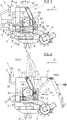
- each rear spar has two coupling points intended to receive a coupling device for seed drill or directly a seed drill.
- the coupling structure also includes a rear beam. This extends between the upper ends of the rear beams, at least substantially parallel to the upper beam and is fixed at each of its longitudinal ends to the corresponding rear beam.
- the support beams are rigidly linked to the coupling structure by means of angles extending at least substantially parallel to the support beams and a number of which is arranged near the front edge of the support beams while the number remaining extends near the rear edge of said support beams.
- the coupling structure extends at least substantially symmetrically with respect to a vertical median plane directed along the direction of work and containing the middle of the outer ends of the support beams.
- the coupling structure is produced largely by means of tubes with rectangular section.
- the latter comprises a support on which the central casing is arranged.
- the input shaft of this central casing extends at least substantially in a vertical median plane directed in the direction of work and containing the middle of the outer ends of the support beams.
- the central casing drives each of the two lateral casings by means of a telescopic shaft with corresponding universal joints extending transversely to the direction of work.
- each lateral casing which is intended to transmit the movement received from the central casing to the drive members of the support beam, is advantageously fixed at least substantially in the middle of the corresponding support beam.
- the two support beams can have at least substantially the same length and at least substantially the same number of rotors.
- each support beam prefferably be provided with a roller guided in the rear ends of a lateral arm and of a central arm, the front ends of which are linked to said support beam.
- the rotary harrow according to the invention comprises a single central arm in the rear end of which the central ends of the two rollers are guided.
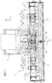
- This includes a hitch structure (2) intended to be linked to the three-point hitch (3) of an agricultural tractor (4) and two support beams (5) rigidly connected to said hitch structure (2). These two support beams (5) extend transversely to the working direction (6), at least substantially in the extension of one another and following one another.
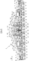
- Each support beam (5) essentially comprises a box (7) under which soil working tools (8) are arranged.
- a roller (9) This roller (9), of the "Packer" type in the example shown, is guided in the rear ends of two arms (10, 11): a lateral arm (10) specific to each roller (9) and a central arm ( 11) common to the two rollers (9).
- the lateral arm (10) and the central arm (11) are connected to the box (7) by means of an articulation (12) with an axis parallel to the support beams (5).
- an adjustment device (13) This is known to those skilled in the art and makes it possible to limit the height movement of the roller (9) relative to the box (7).
- the roller (9) rolls on the ground. In this way, it determines the working depth of the soil working tools (8).
- the soil working tools (8) are connected to rotors (14).
- Each rotor (14) crosses at least substantially vertically the bottom of the box (7) and is provided, at its lower part, with at least one of said soil working tools (8) which extends downwards.
- said rotor (14) is linked to the box (7) by means of a cylindrical articulation (15) with an axis directed at least substantially vertically.
- a toothed wheel (16) arranged inside the box (7) ( Figures 1 and 3). In FIG. 1, it can be seen in particular that the toothed wheels (16) of each box (7) are aligned and mesh in pairs.
- each box (7) is additionally arranged a lateral casing (17).
- This is at least substantially in the central part of the box (7) and is produced in the form of a gearbox.
- the lateral casing (17) receives the rotational movement by means of an input shaft (18) directed transversely to the working direction (6) and oriented towards the adjacent support beam (5).
- the rotational movement is then communicated via the side casing (17) to one of the toothed wheels (16) of the box (7) which transmits it to the rotors (14) to which the soil working tools are attached ( 8).
- this rotary harrow (1) is produced by means of several support beams (5). Thanks to this principle, the support beams (5) can be sold either individually or juxtaposed, which has the effect of obtaining a relatively low production cost.
- each support beam (5) of this rotary harrow (1) requires only space-saving parts therefore easily machinable, transportable and storable.
- the rigid connection between the support beams (5) and the hitching structure (2) also allows precise and definitive positioning of a support beam (5) relative to the other, that is to say that '' it is easily possible to position the soil working tools (8) of one support beam (5) relative to the soil working tools (8) of the other support beam (5) so that the strip of central earth is properly worked.
- the coupling structure (2) for its part, comprises in particular a lower beam (19). This extends at least substantially parallel to the two support beams (5) and is arranged in the close vicinity of said support beams (5). Indeed, it appears in the figures that the rear face (20) of this lower beam (19) extends at least substantially in the vicinity of the front edge (21) of the two support beams (5). In addition, the upper face (22) of each support beam (5) extends, in rear view, at least substantially at the level of the middle part of the lower beam (19).
- the lower beam (19) is also fixed to the two support beams (5) at each of its longitudinal ends (23) as well as at its central part (24).
- the lower beam (19) comprises, at each of its longitudinal ends (23), a wing (25) directed towards the rear.
- Each wing (25) rests on top of the corresponding support beam (5) to which it is fixed near the front edge (21) and near the rear edge (26) of said support beam (5).
- Each wing (25) or each longitudinal end (23) of the lower beam (19) extends from the rest in the outer half of the corresponding support beam (5).
- each of these lower coupling points (27) comprises a yoke (28) which is linked to the lower beam (19) by means of a cylindrical articulation (29) of geometric axis (29A) at least substantially parallel to the two support beams (5).
- each lower beam (30) extends rearwards from the lower beam (19) to which it is fixed.
- each lower beam (30) rests on top of the corresponding support beam (5) to which it is fixed near the front edge (21) and near the rear edge (26) of said support beam (5).
- each lower beam (30) extends at least substantially in a vertical plane (31) directed along the working direction (6) and containing the corresponding lower coupling point (27).
- the coupling structure (2) also comprises an upright (32) which extends upwards from the lower beam (19) to which it is fixed. At their upper end, the uprights (32) are rigidly linked together by means of an upper beam (33). The latter extends at least substantially parallel to the lower beam (19) and supports the upper coupling point (34).
- the hitching structure (2) additionally comprises two front side members (35).
- Each front spar (35) extends between a longitudinal end of the upper beam (33) and the corresponding longitudinal end (23) of the lower beam (19).
- each front spar (35) is moreover linked to the lower beam (19) by means of a crosspiece (36) directed at least substantially vertically.
- the coupling structure (2) also comprises an upper beam (37). This extends at least substantially horizontally rearward from the upper beam (33) to which it is fixed. At the rear end of each upper beam (37) is fixed a rear beam (38) which extends rearward and downward to the rear edge (26) of the corresponding support beam (5).
- each upper beam (37) and the corresponding rear beam (38) extend, like the lower beam (30), at least substantially in the vertical plane (31) directed along the working direction (6) and containing the corresponding lower coupling point (27). Therefore, each rear spar (38) can be fixed to the respective lower beam (30) near the rear edge (26) of the corresponding support beam (5).
- the coupling structure (2) is linked to the support beams (5) by means of angles (39). These extend at least substantially parallel to the support beams (5); a number of them are arranged near the front edge (21) of the support beams (5) while the remaining number extends near the rear edge (26) of said support beams (5). Thanks to this arrangement, each support beam (5) is linked in a particularly rigid manner to the coupling structure (2).
- the coupling structure (2) extends according to the invention, directly above or in the close vicinity of the front part (21) of the support beams (5), the center of the masses of this harrow rotary (1) is particularly close to the rear wheels of said tractor (4). Therefore, the often very significant weight of this type of machine can easily be supported by the tractor (4).
- each rear spar (38) has two coupling points (40). These four coupling points (40) are intended to receive a coupling device (41) for seed drill.
- a coupling device (41) known to those skilled in the art, is shown in FIG. 4 in two different positions (141, 241): a transport position (241) and a working position (141 ).
- the seed drill (not shown) would be behind the rollers (9) of the rotary harrow (1), while in the transport position (241), the seed drill would be above the roller (9).
- the rotary harrow (1) according to the invention, the center of the masses of which is particularly close to the tractor (4), can easily support this type of mounting.
- the coupling structure (2) comprises a rear beam (42). This extends at least substantially parallel to the upper beam (33) and is fixed to each of these ends longitudinal to the corresponding rear spar (38).
- the coupling structure (2) extends at least substantially symmetrically with respect to a vertical median plane (43) directed along the direction of work (6 ) and containing the upper coupling point (34).
- the coupling structure (2) is produced in part at least using tubes (44) of rectangular section.
- the two support beams (5) are almost identical and that they extend at least substantially symmetrically with respect to the median vertical plane (43 ) defined above. Therefore, the central arm (11) which is common to the two rollers (9), extends at least substantially in the vertical median plane (43).
- a central casing (45) In the median vertical plane (43) is also arranged a central casing (45). This is removably attached to the coupling structure (2) by means of a support (46) on which it rests.
- the central casing (45) comprises an input shaft (47) directed in the working direction (6) and passing through the central casing (45) right through to allow the drive of a possible seed drill.
- each of these output shafts (48) is integral with a corresponding bevel gear (49) meshing with another bevel gear (50) integral with the input shaft (47).
- the soil working tools (8) are driven from the PTO (not shown) of the agricultural tractor (4) which drives, via a telescopic shaft with universal joints (51) , the input shaft (47) of the central casing (45). Inside the central casing (45), the input shaft (47) transmits the rotational movement to each output shaft (48) to the using the corresponding pair of bevel gears (49, 50).
- a respective telescopic shaft with universal joints (52) extending between the upright (32) and the rear spar (38) rotates each shaft lateral outlet (48) of the central casing (45) with the input shaft (18) of the corresponding lateral casing (17). Then, the rotary movement is, as said previously, communicated to one of the toothed wheels (16) of the corresponding box (7) which transmits it to the rotors (14) to which the soil working tools (8) are fixed.
Landscapes
- Life Sciences & Earth Sciences (AREA)
- Engineering & Computer Science (AREA)
- Mechanical Engineering (AREA)
- Soil Sciences (AREA)
- Environmental Sciences (AREA)
- Agricultural Machines (AREA)
- Soil Working Implements (AREA)
Applications Claiming Priority (2)
| Application Number | Priority Date | Filing Date | Title |
|---|---|---|---|
| FR9102526A FR2673069B1 (fr) | 1991-02-27 | 1991-02-27 | Herse rotative comportant plusieurs poutres support liees rigidement a une structure d'attelage perfectionnee. |
| FR9102526 | 1991-02-27 |
Publications (2)
| Publication Number | Publication Date |
|---|---|
| EP0501899A1 true EP0501899A1 (de) | 1992-09-02 |
| EP0501899B1 EP0501899B1 (de) | 1995-11-15 |
Family
ID=9410279
Family Applications (1)
| Application Number | Title | Priority Date | Filing Date |
|---|---|---|---|
| EP19920440022 Expired - Lifetime EP0501899B1 (de) | 1991-02-27 | 1992-02-12 | Kreiselegge mit mehreren starr mit einer verbesserten Anbauvorrichtung verbundenen Tragbalken |
Country Status (3)
| Country | Link |
|---|---|
| EP (1) | EP0501899B1 (de) |
| DE (1) | DE69206015T2 (de) |
| FR (1) | FR2673069B1 (de) |
Cited By (1)
| Publication number | Priority date | Publication date | Assignee | Title |
|---|---|---|---|---|
| CN111819918A (zh) * | 2020-07-06 | 2020-10-27 | 泰州樱田农机制造有限公司 | 折叠式水田耕整机 |
Citations (5)
| Publication number | Priority date | Publication date | Assignee | Title |
|---|---|---|---|---|
| FR2169144A1 (de) * | 1972-01-24 | 1973-09-07 | Lely Nv C Van Der | |
| US4171725A (en) * | 1977-03-15 | 1979-10-23 | Saugstad Osten E | Rotary harrow |
| FR2443187A1 (fr) * | 1978-12-08 | 1980-07-04 | Patent Concern Nv | Machine pour la preparation du sol, de type herse |
| EP0200664A1 (de) * | 1985-04-15 | 1986-11-05 | Kuhn S.A. | Kombinierte Landmaschine bestehend aus einer Bodenbearbeitungsmaschine und einer Walze |
| EP0264987A1 (de) * | 1986-09-26 | 1988-04-27 | C. van der Lely N.V. | Bodenbearbeitungsmaschine |
-
1991
- 1991-02-27 FR FR9102526A patent/FR2673069B1/fr not_active Expired - Fee Related
-
1992
- 1992-02-12 EP EP19920440022 patent/EP0501899B1/de not_active Expired - Lifetime
- 1992-02-12 DE DE1992606015 patent/DE69206015T2/de not_active Expired - Fee Related
Patent Citations (5)
| Publication number | Priority date | Publication date | Assignee | Title |
|---|---|---|---|---|
| FR2169144A1 (de) * | 1972-01-24 | 1973-09-07 | Lely Nv C Van Der | |
| US4171725A (en) * | 1977-03-15 | 1979-10-23 | Saugstad Osten E | Rotary harrow |
| FR2443187A1 (fr) * | 1978-12-08 | 1980-07-04 | Patent Concern Nv | Machine pour la preparation du sol, de type herse |
| EP0200664A1 (de) * | 1985-04-15 | 1986-11-05 | Kuhn S.A. | Kombinierte Landmaschine bestehend aus einer Bodenbearbeitungsmaschine und einer Walze |
| EP0264987A1 (de) * | 1986-09-26 | 1988-04-27 | C. van der Lely N.V. | Bodenbearbeitungsmaschine |
Cited By (1)
| Publication number | Priority date | Publication date | Assignee | Title |
|---|---|---|---|---|
| CN111819918A (zh) * | 2020-07-06 | 2020-10-27 | 泰州樱田农机制造有限公司 | 折叠式水田耕整机 |
Also Published As
| Publication number | Publication date |
|---|---|
| FR2673069B1 (fr) | 1994-09-16 |
| FR2673069A1 (fr) | 1992-08-28 |
| DE69206015T2 (de) | 1996-07-04 |
| EP0501899B1 (de) | 1995-11-15 |
| DE69206015D1 (de) | 1995-12-21 |
Similar Documents
| Publication | Publication Date | Title |
|---|---|---|
| EP0163587B1 (de) | Mähmaschine | |
| EP0429381A1 (de) | Landmaschine mit verbesserter Aufhängungsvorrichtung der Arbeitswerkzeugeeinheit | |
| EP0429382A1 (de) | Mähmaschine mit einer sich quer zur Fahrtrichtung erstreckenden Arbeitswerkzeugeeinheit | |
| EP2699074B1 (de) | Landwirtschaftliche maschine mit verbesserter faltvorrichtung | |
| FR2631208A1 (fr) | Perfectionnement aux machines agricoles avec un chassis porte-outils articule | |
| EP0529684B1 (de) | Bodenbearbeitungsmaschine mit verbessertem Stabilisierungsorgan | |
| FR2533188A1 (fr) | Tracteur agricole a roues multiples | |
| EP1142468B1 (de) | Heuwerbungsmaschine | |
| FR2552616A1 (fr) | Machine pour travailler le sol, munie d'un moteur | |
| EP0954956B1 (de) | Heuwerbungsmaschine | |
| EP2820931A1 (de) | Bodenbearbeitungsmaschine mit einer verbesserten Vorrichtung zum Einstellen der Arbeitstiefe | |
| EP0501899B1 (de) | Kreiselegge mit mehreren starr mit einer verbesserten Anbauvorrichtung verbundenen Tragbalken | |
| FR2558679A1 (fr) | Construction de rouleau pour une machine pour travailler le sol | |
| FR2552617A1 (fr) | Machine pour travailler le sol, munie d'un rouleau et de points d'accouplement | |
| FR2551308A1 (fr) | Machine pour travailler le sol munie de moyens de relevage perfectionnes | |
| FR2476966A1 (fr) | Herse rotative comportant un dispositif d'attelage perfectionne | |
| EP0914766B1 (de) | Heuwerbungsmachine | |
| FR2541553A1 (fr) | Herse rotative munie d'un rouleau entraine | |
| EP0733302B1 (de) | Heuwerbungsmaschine | |
| FR2533177A1 (fr) | Tracteur agricole a prises de forces multiples | |
| EP0307334B1 (de) | Bodenbearbeitungsmaschine mit Scharen und Rotor | |
| EP0615681B1 (de) | Landwirtschaftliche Bodenbearbeitungsmaschine mit grosser Breite, die sich besser an die Bodenunebenheit anpasst | |
| EP0772970A1 (de) | Heuwerbungsmaschine, insbesondere ein Zett-Wender | |
| EP0486415B1 (de) | Mähmaschine mit unabhängigem Rahmen, der Aufhängungs- und Erleichterungsvorrichtungen aufweisst | |
| FR2533190A1 (fr) | Tracteur agricole dont les dispositifs d'attelage sont montes pres de l'avant des roues |
Legal Events
| Date | Code | Title | Description |
|---|---|---|---|
| PUAI | Public reference made under article 153(3) epc to a published international application that has entered the european phase |
Free format text: ORIGINAL CODE: 0009012 |
|
| AK | Designated contracting states |
Kind code of ref document: A1 Designated state(s): DE DK FR GB IT NL |
|
| 17P | Request for examination filed |
Effective date: 19930211 |
|
| 17Q | First examination report despatched |
Effective date: 19940218 |
|
| GRAA | (expected) grant |
Free format text: ORIGINAL CODE: 0009210 |
|
| AK | Designated contracting states |
Kind code of ref document: B1 Designated state(s): DE DK FR GB IT NL |
|
| PG25 | Lapsed in a contracting state [announced via postgrant information from national office to epo] |
Ref country code: DK Effective date: 19951115 |
|
| ITF | It: translation for a ep patent filed | ||
| REF | Corresponds to: |
Ref document number: 69206015 Country of ref document: DE Date of ref document: 19951221 |
|
| GBT | Gb: translation of ep patent filed (gb section 77(6)(a)/1977) |
Effective date: 19960123 |
|
| PLAV | Examination of admissibility of opposition |
Free format text: ORIGINAL CODE: EPIDOS OPEX |
|
| PLBQ | Unpublished change to opponent data |
Free format text: ORIGINAL CODE: EPIDOS OPPO |
|
| PLBI | Opposition filed |
Free format text: ORIGINAL CODE: 0009260 |
|
| 26 | Opposition filed |
Opponent name: MAASLAND N.V. Effective date: 19960815 |
|
| PLAV | Examination of admissibility of opposition |
Free format text: ORIGINAL CODE: EPIDOS OPEX |
|
| PLBF | Reply of patent proprietor to notice(s) of opposition |
Free format text: ORIGINAL CODE: EPIDOS OBSO |
|
| NLR1 | Nl: opposition has been filed with the epo |
Opponent name: MAASLAND N.V. |
|
| PLBF | Reply of patent proprietor to notice(s) of opposition |
Free format text: ORIGINAL CODE: EPIDOS OBSO |
|
| PLBF | Reply of patent proprietor to notice(s) of opposition |
Free format text: ORIGINAL CODE: EPIDOS OBSO |
|
| PLBQ | Unpublished change to opponent data |
Free format text: ORIGINAL CODE: EPIDOS OPPO |
|
| PLAB | Opposition data, opponent's data or that of the opponent's representative modified |
Free format text: ORIGINAL CODE: 0009299OPPO |
|
| R26 | Opposition filed (corrected) |
Opponent name: MAASLAND N.V. Effective date: 19960815 |
|
| NLR1 | Nl: opposition has been filed with the epo |
Opponent name: MAASLAND N.V. |
|
| PLBO | Opposition rejected |
Free format text: ORIGINAL CODE: EPIDOS REJO |
|
| PLBN | Opposition rejected |
Free format text: ORIGINAL CODE: 0009273 |
|
| 27O | Opposition rejected |
Effective date: 19990312 |
|
| REG | Reference to a national code |
Ref country code: GB Ref legal event code: IF02 |
|
| PGFP | Annual fee paid to national office [announced via postgrant information from national office to epo] |
Ref country code: NL Payment date: 20080124 Year of fee payment: 17 Ref country code: IT Payment date: 20080213 Year of fee payment: 17 Ref country code: GB Payment date: 20080129 Year of fee payment: 17 Ref country code: DE Payment date: 20080208 Year of fee payment: 17 |
|
| PGFP | Annual fee paid to national office [announced via postgrant information from national office to epo] |
Ref country code: FR Payment date: 20080228 Year of fee payment: 17 |
|
| GBPC | Gb: european patent ceased through non-payment of renewal fee |
Effective date: 20090212 |
|
| NLV4 | Nl: lapsed or anulled due to non-payment of the annual fee |
Effective date: 20090901 |
|
| REG | Reference to a national code |
Ref country code: FR Ref legal event code: ST Effective date: 20091030 |
|
| PG25 | Lapsed in a contracting state [announced via postgrant information from national office to epo] |
Ref country code: NL Free format text: LAPSE BECAUSE OF NON-PAYMENT OF DUE FEES Effective date: 20090901 |
|
| PG25 | Lapsed in a contracting state [announced via postgrant information from national office to epo] |
Ref country code: DE Free format text: LAPSE BECAUSE OF NON-PAYMENT OF DUE FEES Effective date: 20090901 |
|
| PG25 | Lapsed in a contracting state [announced via postgrant information from national office to epo] |
Ref country code: GB Free format text: LAPSE BECAUSE OF NON-PAYMENT OF DUE FEES Effective date: 20090212 Ref country code: FR Free format text: LAPSE BECAUSE OF NON-PAYMENT OF DUE FEES Effective date: 20090302 |
|
| PG25 | Lapsed in a contracting state [announced via postgrant information from national office to epo] |
Ref country code: IT Free format text: LAPSE BECAUSE OF NON-PAYMENT OF DUE FEES Effective date: 20090212 |