EP0501878B1 - Vibro-isolating support structure for engine of industrial vehicle - Google Patents
Vibro-isolating support structure for engine of industrial vehicle Download PDFInfo
- Publication number
- EP0501878B1 EP0501878B1 EP92400490A EP92400490A EP0501878B1 EP 0501878 B1 EP0501878 B1 EP 0501878B1 EP 92400490 A EP92400490 A EP 92400490A EP 92400490 A EP92400490 A EP 92400490A EP 0501878 B1 EP0501878 B1 EP 0501878B1
- Authority
- EP
- European Patent Office
- Prior art keywords
- engine
- vibration isolator
- vibro
- rubber vibration
- transmission
- Prior art date
- Legal status (The legal status is an assumption and is not a legal conclusion. Google has not performed a legal analysis and makes no representation as to the accuracy of the status listed.)
- Expired - Lifetime
Links
- 230000005540 biological transmission Effects 0.000 claims description 31
- 238000006073 displacement reaction Methods 0.000 description 3
- 230000000694 effects Effects 0.000 description 2
- 238000010008 shearing Methods 0.000 description 2
- 229910000831 Steel Inorganic materials 0.000 description 1
- 239000002184 metal Substances 0.000 description 1
- 238000000465 moulding Methods 0.000 description 1
- 230000000149 penetrating effect Effects 0.000 description 1
- 230000002093 peripheral effect Effects 0.000 description 1
- 230000001105 regulatory effect Effects 0.000 description 1
- 230000035939 shock Effects 0.000 description 1
- 239000010959 steel Substances 0.000 description 1
Images


Classifications
-
- B—PERFORMING OPERATIONS; TRANSPORTING
- B60—VEHICLES IN GENERAL
- B60K—ARRANGEMENT OR MOUNTING OF PROPULSION UNITS OR OF TRANSMISSIONS IN VEHICLES; ARRANGEMENT OR MOUNTING OF PLURAL DIVERSE PRIME-MOVERS IN VEHICLES; AUXILIARY DRIVES FOR VEHICLES; INSTRUMENTATION OR DASHBOARDS FOR VEHICLES; ARRANGEMENTS IN CONNECTION WITH COOLING, AIR INTAKE, GAS EXHAUST OR FUEL SUPPLY OF PROPULSION UNITS IN VEHICLES
- B60K5/00—Arrangement or mounting of internal-combustion or jet-propulsion units
- B60K5/12—Arrangement of engine supports
- B60K5/1208—Resilient supports
- B60K5/1216—Resilient supports characterised by the location of the supports relative to the motor or to each other
-
- F—MECHANICAL ENGINEERING; LIGHTING; HEATING; WEAPONS; BLASTING
- F16—ENGINEERING ELEMENTS AND UNITS; GENERAL MEASURES FOR PRODUCING AND MAINTAINING EFFECTIVE FUNCTIONING OF MACHINES OR INSTALLATIONS; THERMAL INSULATION IN GENERAL
- F16F—SPRINGS; SHOCK-ABSORBERS; MEANS FOR DAMPING VIBRATION
- F16F15/00—Suppression of vibrations in systems; Means or arrangements for avoiding or reducing out-of-balance forces, e.g. due to motion
- F16F15/02—Suppression of vibrations of non-rotating, e.g. reciprocating systems; Suppression of vibrations of rotating systems by use of members not moving with the rotating systems
- F16F15/04—Suppression of vibrations of non-rotating, e.g. reciprocating systems; Suppression of vibrations of rotating systems by use of members not moving with the rotating systems using elastic means
- F16F15/08—Suppression of vibrations of non-rotating, e.g. reciprocating systems; Suppression of vibrations of rotating systems by use of members not moving with the rotating systems using elastic means with rubber springs ; with springs made of rubber and metal
-
- B—PERFORMING OPERATIONS; TRANSPORTING
- B66—HOISTING; LIFTING; HAULING
- B66F—HOISTING, LIFTING, HAULING OR PUSHING, NOT OTHERWISE PROVIDED FOR, e.g. DEVICES WHICH APPLY A LIFTING OR PUSHING FORCE DIRECTLY TO THE SURFACE OF A LOAD
- B66F9/00—Devices for lifting or lowering bulky or heavy goods for loading or unloading purposes
- B66F9/06—Devices for lifting or lowering bulky or heavy goods for loading or unloading purposes movable, with their loads, on wheels or the like, e.g. fork-lift trucks
- B66F9/075—Constructional features or details
- B66F9/07586—Suspension or mounting of wheels on chassis
-
- F—MECHANICAL ENGINEERING; LIGHTING; HEATING; WEAPONS; BLASTING
- F16—ENGINEERING ELEMENTS AND UNITS; GENERAL MEASURES FOR PRODUCING AND MAINTAINING EFFECTIVE FUNCTIONING OF MACHINES OR INSTALLATIONS; THERMAL INSULATION IN GENERAL
- F16F—SPRINGS; SHOCK-ABSORBERS; MEANS FOR DAMPING VIBRATION
- F16F1/00—Springs
- F16F1/36—Springs made of rubber or other material having high internal friction, e.g. thermoplastic elastomers
- F16F1/38—Springs made of rubber or other material having high internal friction, e.g. thermoplastic elastomers with a sleeve of elastic material between a rigid outer sleeve and a rigid inner sleeve or pin, i.e. bushing-type
- F16F1/387—Springs made of rubber or other material having high internal friction, e.g. thermoplastic elastomers with a sleeve of elastic material between a rigid outer sleeve and a rigid inner sleeve or pin, i.e. bushing-type comprising means for modifying the rigidity in particular directions
Definitions
- the present invention relates to a structure of an apparatus for supporting an engine of an industrial vehicle such as a fork lift truck in a vibro-isolating manner.
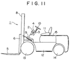
- Fig. 11 shows an external appearance of a fork lift truck as an example of an industrial vehicle.
- a fork 5 of a fork lift truck 1 is fitted to a bracket 6 and ascends and descends along a mast 8.
- the mast 8 ascends and descends by means of a lift cylinder not shown, and tilts fore and aft by means of a tilt cylinder 9.
- Reference numeral 2 represents a parking brake lever
- 3 represents a grip thereof
- 4 represents a console box
- 10 represents a handle
- 11 represents a driver's seat
- 12 represents a body
- 13 represents a front wheel
- 14 represents a rear wheel
- 15 represents an engine cover.
- Fig. 12 shows a conventional engine support structure in the fork lift truck 1 corresponding to the preamble of claim 1.
- Fig. 13 shows a rubber vibration isolator 17 which has been heretofore used.
- the rubber vibration isolator 17 has a simple cylindrical form, and intervenes lengthwise (i.e., such that its axis points to a vertical direction) between respective L-shaped brackets 18 fitted to both side faces of an engine 16 and respective U-shaped brackets 19 fitted to a body frame.
- a transmission 20 and a front axle housing 21 are coupled with the engine 16 in this order, and an axle support 22 supporting the axle housing 21 is coupled tightly with a body frame by bolts at a sector section 22A thereof.
- 21A represents an axle shaft
- 23 represents an oil pan.
- the vibration of the engine 16 is transmitted to the axle housing 21 and the axle shaft 21A through the transmission 20, and transmitted to the body frame therefrom. Therefore, vibration is transmitted to the handle 10 and the driver's seat 11, and thus, the operator may feel unpleasant vibrations.
- the rubber vibration isolator 17 is of a simple cylindrical form and it is merely installed lengthwise(its axis points to a vertical direction). Thus, the vibro-isolating effect is small, and hence, still further improvement is needed.
- a vibro-isolating support structure for an engine of an industrial vehicle is defined in claim 1. Accordingly, it comprises a cylindrical crosswise rubber vibration isolator made to intervene between an engine and a body, a universal joint connected between an output shaft of a transmission and an input shaft of a transfer mechanism coupled with an axle, and a cylindrical crosswise rubber vibration isolator made to intervene between a transmission case and a transfer case.
- the cylindrical crosswise rubber vibration isolator (arranged so that the axis of the cylinder is in a horizontal position) absorbs vibration of the engine by shearing force. Further, the cylindrical crosswise rubber vibration isolator can provide a spring constant optimum for vibro-isolating support according to its shape given at the time of molding, and give a stopper function for regulating maximum displacements in vertical and horizontal directions, respectively, easily. Hence, the vibro-isolating effect is high as compared with a conventional cylindrical lengthwise isolator (arranged so that the axis of the cylinder is in a vertical direction).
- cylindrical crosswise rubber isolator is made to intervene not only between the engine and the body, but also between the transmission case and the transfer case, and the output shaft of the transmission and the input shaft of the transfer mechanism are connected through a universal joint. Accordingly, the vibration of the engine is no longer transmitted to the body frame through the transmission.
- covers of respective cases and brackets of cylindrical crosswise rubber vibration isolators are fastened together on the transmission and the transfer, thus obtaining a simple structure.
- Fig. 1 shows an embodiment of the present invention in a plan view.
- a transmission case 20 is coupled with an engine 16.
- a transfer mechanism 24 is coupled with a front axle.
- the output shaft of the transmission 20 and the input shaft of the transfer mechanism 24 are connected with each other by a cross universal joint 25.
- 26 represents a cover disposed at the end portion of the transmission 20, and 27 represents a cover disposed at the end portion of the transfer mechanism 24.
- Fig. 2 shows a view showing the embodiment from its side.
- one cylindrical crosswise rubber vibration isolator 28 is disposed on either side of the engine 16 with respect to front and back directions of the vehicle so as to intervene between a body frame 29 and the engine 16.
- 30 and 31 represent mounting brackets of the rubber vibration isolators 28, and are fixed to the engine 16 and the frame 29 by bolts, respectively.
- one cylindrical crosswise rubber vibration isolator 32 is disposed on either side with respect to the universal joint 25 so as to intervene between the transmission 20 and the transfer mechanism 24, too.
- Mounting brackets 33 and 34 of these rubber vibration isolators 32 are fastened to the transmission 20 together with a cover 26 thereof and to the transfer 24 together with a cover 27 thereof by bolts 35.
- the respective rubber vibration isolators 28 and 32 are disposed so that their axes are perpendicular to the longitudinal direction of the vehicle.
- a front axle housing 21 is fixed to the body frame by an axle support 22.
- Fig. 3 shows a cross-sectional structure of the rubber vibration isolator 28 mounted on the engine 16, and Fig. 4 is a view in the direction of IV in Fig. 3.
- the rubber vibration isolator 32 between the transmission 20 and the transfer mechanism 24 has basically the same structure as above , and only the configuration of the bracket is different slightly.
- a rubber compact 37 is fixed in a ring 36 made of metal such as steel, and pipe 38 is fixed in the rubber compact 37.
- Two gap sections 37A penetrate through the rubber compact 37 as the compact is molded.
- rubber sections 37B for stopper are molded on the side of the ring 36 facing the gap sections 37A. Both ends of these rubber sections 37B for stopper project slightly from the ring 36.
- the rubber vibration isolator 28 is fixed to a U-shaped support 30A of a bracket 30 for the engine by bolts 39 and nuts 40 penetrating through the pipe 38.
- This support 30A is welded to a rib 30C of a bracket body 30B.
- a pointed end of a bracket 31 for the frame has a U shape.
- This U-shaped pointed end section 31A is fixed to the outer periphery of the ring 36 of the rubber vibration isolator 28.
- 31B represents a support section having a depression midway.
- the rubber vibration isolators 28 and 32 are used so that one of the two gap sections 37A is positioned above the other, and the pipe 38 is positioned a little above the center of the ring 36 in a free state as shown in Fig. 5 (a). Further, it is designed so that the pipe 38 goes down so as to be positioned at the center of the ring 36 in a loaded state where the engine is mounted. With this, the vertical vibration of the engine is absorbed effectually by the shearing force of the rubber compact 37 as shown in Fig. 5 (b). The crosswise vibration of the engine is absorbed through deformation as shown in Fig. 6. Also, when the crosswise vibration is large, the pointed end of the rubber section 37B projecting as a stopper abuts against the U-shaped support 30A of the bracket for the engine, thereby to delimit the maximum displacement without undue shocks.
- Fig. 7 shows a structure of a bracket of the rubber vibration isolator 32 between the transmission 20 and the transfer mechanism 24.
- a U-shaped support 33A of a bracket 33 for the transmission is fixed to a pipe at the center of the rubber vibration isolator 32 by a bolt 39.
- This support 33A is welded to a bracket body 33B having an L shape.
- This bracket body 33B is fixed to the transmission 20 together with the transmission case 26 by bolts 35.
- a U-shaped pointed portion 34A of a bracket 34 for the transfer is fixed to a ring 36 on the outer periphery of the rubber vibration isolator 32.
- the bracket body 34B is fixed to the transfer mechanism 24 together with the cover of the transfer case 27 by bolts 35.
- Fig. 8 shows another embodiment in a plan view.
- the embodiment shown in Fig. 8 includes four cylindrical crosswise rubber vibration isolators 28 and 32 arranged so that their axial directions are in parallel with the longitudinal direction of the vehicle body, and differs from the previous embodiment shown in Fig. 1 in the point described above. Thus, these embodiments differ only in the bracket structures of respective rubber vibration isolators 28 and 32.
- the other members and the like are the same, and hence, the same symbols are assigned and duplicate description is omitted herein.
- Fig. 9 shows brackets 41 and 42 for mounting a rubber vibration isolator 28 between the engine 16 and the frame 29.
- a U-shaped support 41A of the bracket 41 for the engine is fixed sideways to a pipe at the center of the rubber vibration isolator 28 by a bolt 39.
- This support 41A is welded to an L-shaped bracket body 41B.
- This bracket body 41B is fixed to the engine 16 by bolts.
- a U-shaped pointed end section 42A is fixed to a ring 36 on the outer periphery of the rubber vibration isolator 28, and a T-shaped bracket body 42B having a rib 42C is fixed to the frame 29 by bolts.
- Fig. 10 shows brackets 43 and 44 for mounting a rubber vibration isolator 32 between the transmission 20 and the transfer mechanism 24.
- the bracket 43 for the transmission has a transverse U-shaped support 43A.
- the rubber vibration isolator 32 is fixed to the U-shaped support 43A by a bolt 39 inserted through a central pipe of the rubber vibration isolator 32.
- the transverse U-shaped support 43A has an L-shaped section 43B, and is fastened together with the transmission cover 26 by using holes bored at the pointed end of this L-shaped section 43B. Bolting operation is performed in a space between the U-shaped support 43A and the L-shaped section 43B.
- the bracket 44 for the transfer mechanism has a U-shaped pointed end section 44A, and the outer peripheral ring 36 of the rubber vibration isolator 32 is fixed to this U-shaped pointed end section 44A.
- the bracket 44 extends from the back of a U-shaped pointed end section 44A to include a U-shaped section 44B, and is fastened together with the transfer case cover 27 by using holes 44C bored at the U-shaped section 44B. Then, bolting operation is performed in a space secured by the U-shaped section 44B.
- vibro-isolating operation is very effectual by adopting the cylindrical crosswise rubber vibration isolator. Furthermore, by connecting, not only between the engine and the frame, but also the output shaft of the transmission and the input shaft of the transfer mechanism with a universal joint and by having a rubber vibration isolator intervene also between these transmission and transfer mechanism, it is also possible to prevent the vibration of the engine from transmitting to the frame through the axle housing and the like. Further, due to the structure that respective covers of the transmission and the transfer mechanism and the bracket of the rubber vibration isolator are fastened together, the structure is simplified.
Landscapes
- Engineering & Computer Science (AREA)
- Mechanical Engineering (AREA)
- Transportation (AREA)
- General Engineering & Computer Science (AREA)
- Structural Engineering (AREA)
- Combustion & Propulsion (AREA)
- Chemical & Material Sciences (AREA)
- Geology (AREA)
- Life Sciences & Earth Sciences (AREA)
- Civil Engineering (AREA)
- Physics & Mathematics (AREA)
- Acoustics & Sound (AREA)
- Aviation & Aerospace Engineering (AREA)
- Vibration Prevention Devices (AREA)
- Arrangement Or Mounting Of Propulsion Units For Vehicles (AREA)
- Forklifts And Lifting Vehicles (AREA)
- Arrangement Of Transmissions (AREA)
Description
- The present invention relates to a structure of an apparatus for supporting an engine of an industrial vehicle such as a fork lift truck in a vibro-isolating manner.
- Fig. 11 shows an external appearance of a fork lift truck as an example of an industrial vehicle. In Fig. 11, a
fork 5 of a fork lift truck 1 is fitted to abracket 6 and ascends and descends along amast 8. Themast 8 ascends and descends by means of a lift cylinder not shown, and tilts fore and aft by means of a tilt cylinder 9.Reference numeral 2 represents a parking brake lever, 3 represents a grip thereof, 4 represents a console box, 10 represents a handle, 11 represents a driver's seat, 12 represents a body, 13 represents a front wheel, 14 represents a rear wheel and 15 represents an engine cover. - Fig. 12 shows a conventional engine support structure in the fork lift truck 1 corresponding to the preamble of claim 1. Further, Fig. 13 shows a
rubber vibration isolator 17 which has been heretofore used. Therubber vibration isolator 17 has a simple cylindrical form, and intervenes lengthwise (i.e., such that its axis points to a vertical direction) between respective L-shaped brackets 18 fitted to both side faces of anengine 16 andrespective U-shaped brackets 19 fitted to a body frame. - On the other hand, a
transmission 20 and afront axle housing 21 are coupled with theengine 16 in this order, and anaxle support 22 supporting theaxle housing 21 is coupled tightly with a body frame by bolts at asector section 22A thereof. 21A represents an axle shaft, and 23 represents an oil pan. - In such a vehicle, the vibration of the
engine 16 is transmitted to theaxle housing 21 and theaxle shaft 21A through thetransmission 20, and transmitted to the body frame therefrom. Therefore, vibration is transmitted to thehandle 10 and the driver's seat 11, and thus, the operator may feel unpleasant vibrations. - Further, although the
engine 16 itself is supported through therubber vibration isolator 17, therubber vibration isolator 17 is of a simple cylindrical form and it is merely installed lengthwise(its axis points to a vertical direction). Thus, the vibro-isolating effect is small, and hence, still further improvement is needed. - It is an object of the present invention to provide a vibro-isolating support structure for an engine of an industrial vehicle in which above-described problems of prior art are solved.
- A vibro-isolating support structure for an engine of an industrial vehicle according to the present invention is defined in claim 1. Accordingly, it comprises a cylindrical crosswise rubber vibration isolator made to intervene between an engine and a body, a universal joint connected between an output shaft of a transmission and an input shaft of a transfer mechanism coupled with an axle, and a cylindrical crosswise rubber vibration isolator made to intervene between a transmission case and a transfer case.
- The cylindrical crosswise rubber vibration isolator (arranged so that the axis of the cylinder is in a horizontal position) absorbs vibration of the engine by shearing force. Further, the cylindrical crosswise rubber vibration isolator can provide a spring constant optimum for vibro-isolating support according to its shape given at the time of molding, and give a stopper function for regulating maximum displacements in vertical and horizontal directions, respectively, easily. Hence, the vibro-isolating effect is high as compared with a conventional cylindrical lengthwise isolator (arranged so that the axis of the cylinder is in a vertical direction).
- Further, the cylindrical crosswise rubber isolator is made to intervene not only between the engine and the body, but also between the transmission case and the transfer case, and the output shaft of the transmission and the input shaft of the transfer mechanism are connected through a universal joint. Accordingly, the vibration of the engine is no longer transmitted to the body frame through the transmission.
- Furthermore, covers of respective cases and brackets of cylindrical crosswise rubber vibration isolators are fastened together on the transmission and the transfer, thus obtaining a simple structure.
-
- Fig. 1 is a plan view showing an embodiment of the present invention;
- Fig. 2 is a view seeing Fig. 1 from the side thereof;
- Fig. 3 is a longitudinal sectional view of a cylindrical crosswise rubber vibration isolator between the engine and the frame shown in Fig. 1;
- Fig. 4 is a view in the direction IV shown in Fig. 3;
- Fig. 5 shows cross-sectional views of a cylindrical crosswise rubber vibration isolator;
- Fig. 6 is a view showing the operation of a cylindrical crosswise rubber vibration isolator against axial displacement;
- Fig. 7 is a view showing a structure of a bracket of a cylindrical crosswise rubber vibration isolator between the transmission case and the transfer case shown in Fig. 1;
- Fig. 8 is a plan view showing another embodiment of the present invention;
- Fig. 9 is a view showing a structure of a bracket of a cylindrical crosswise rubber vibration isolator between the engine and the frame shown in Fig. 8;
- Fig. 10 shows a structure of a bracket of a cylindrical crosswise rubber vibration isolator between the transmission case and the transfer case shown in Fig. 8;
- Fig. 11 is a sketch drawing of a fork lift truck;
- Fig. 12 is a side view showing a conventional vibro-isolating support structure; and
- Fig. 13 is a perspective view of the rubber vibration isolator shown in Fig. 12.
- The present invention will be described in detail with reference to embodiments shown in Fig. 1 to Fig. 10.
- Fig. 1 shows an embodiment of the present invention in a plan view. A
transmission case 20 is coupled with anengine 16. Atransfer mechanism 24 is coupled with a front axle. The output shaft of thetransmission 20 and the input shaft of thetransfer mechanism 24 are connected with each other by a crossuniversal joint 25. 26 represents a cover disposed at the end portion of thetransmission transfer mechanism 24. Fig. 2 shows a view showing the embodiment from its side. - Further, one cylindrical crosswise
rubber vibration isolator 28 is disposed on either side of theengine 16 with respect to front and back directions of the vehicle so as to intervene between abody frame 29 and theengine 16. 30 and 31 represent mounting brackets of therubber vibration isolators 28, and are fixed to theengine 16 and theframe 29 by bolts, respectively. - Further, one cylindrical crosswise
rubber vibration isolator 32 is disposed on either side with respect to theuniversal joint 25 so as to intervene between thetransmission 20 and thetransfer mechanism 24, too.Mounting brackets rubber vibration isolators 32 are fastened to thetransmission 20 together with acover 26 thereof and to thetransfer 24 together with acover 27 thereof bybolts 35. - The respective
rubber vibration isolators front axle housing 21 is fixed to the body frame by anaxle support 22. - Next, the cylindrical crosswise
rubber vibration isolators - Fig. 3 shows a cross-sectional structure of the
rubber vibration isolator 28 mounted on theengine 16, and Fig. 4 is a view in the direction of IV in Fig. 3. Therubber vibration isolator 32 between thetransmission 20 and thetransfer mechanism 24 has basically the same structure as above , and only the configuration of the bracket is different slightly. - In Fig. 3 and Fig. 4, a rubber compact 37 is fixed in a
ring 36 made of metal such as steel, andpipe 38 is fixed in therubber compact 37. Twogap sections 37A penetrate through therubber compact 37 as the compact is molded. Further,rubber sections 37B for stopper are molded on the side of thering 36 facing thegap sections 37A. Both ends of theserubber sections 37B for stopper project slightly from thering 36. - Further, the
rubber vibration isolator 28 is fixed to a U-shapedsupport 30A of abracket 30 for the engine bybolts 39 andnuts 40 penetrating through thepipe 38. Thissupport 30A is welded to a rib 30C of abracket body 30B. - On the other hand, a pointed end of a
bracket 31 for the frame has a U shape. This U-shaped pointed end section 31A is fixed to the outer periphery of thering 36 of therubber vibration isolator 28. 31B represents a support section having a depression midway. - The
rubber vibration isolators gap sections 37A is positioned above the other, and thepipe 38 is positioned a little above the center of thering 36 in a free state as shown in Fig. 5 (a). Further, it is designed so that thepipe 38 goes down so as to be positioned at the center of thering 36 in a loaded state where the engine is mounted. With this, the vertical vibration of the engine is absorbed effectually by the shearing force of the rubber compact 37 as shown in Fig. 5 (b). The crosswise vibration of the engine is absorbed through deformation as shown in Fig. 6. Also, when the crosswise vibration is large, the pointed end of therubber section 37B projecting as a stopper abuts against theU-shaped support 30A of the bracket for the engine, thereby to delimit the maximum displacement without undue shocks. - Fig. 7 shows a structure of a bracket of the
rubber vibration isolator 32 between thetransmission 20 and thetransfer mechanism 24. A U-shaped support 33A of abracket 33 for the transmission is fixed to a pipe at the center of therubber vibration isolator 32 by abolt 39. This support 33A is welded to abracket body 33B having an L shape. Thisbracket body 33B is fixed to thetransmission 20 together with thetransmission case 26 bybolts 35. Further, a U-shapedpointed portion 34A of abracket 34 for the transfer is fixed to aring 36 on the outer periphery of therubber vibration isolator 32. Thebracket body 34B is fixed to thetransfer mechanism 24 together with the cover of thetransfer case 27 bybolts 35. - In the next place, another embodiment of the present invention will be described with reference to Fig. 8 to Fig. 10.
- Fig. 8 shows another embodiment in a plan view. The embodiment shown in Fig. 8 includes four cylindrical crosswise
rubber vibration isolators rubber vibration isolators - Fig. 9 shows
brackets rubber vibration isolator 28 between theengine 16 and theframe 29. AU-shaped support 41A of thebracket 41 for the engine is fixed sideways to a pipe at the center of therubber vibration isolator 28 by abolt 39. Thissupport 41A is welded to an L-shaped bracket body 41B. This bracket body 41B is fixed to theengine 16 by bolts. - In the
bracket 42 for the frame, a U-shapedpointed end section 42A is fixed to aring 36 on the outer periphery of therubber vibration isolator 28, and a T-shapedbracket body 42B having arib 42C is fixed to theframe 29 by bolts. - Fig. 10 shows
brackets rubber vibration isolator 32 between thetransmission 20 and thetransfer mechanism 24. Thebracket 43 for the transmission has a transverseU-shaped support 43A. Therubber vibration isolator 32 is fixed to theU-shaped support 43A by abolt 39 inserted through a central pipe of therubber vibration isolator 32. The transverseU-shaped support 43A has an L-shapedsection 43B, and is fastened together with thetransmission cover 26 by using holes bored at the pointed end of this L-shapedsection 43B. Bolting operation is performed in a space between theU-shaped support 43A and the L-shapedsection 43B. - The
bracket 44 for the transfer mechanism has a U-shapedpointed end section 44A, and the outerperipheral ring 36 of therubber vibration isolator 32 is fixed to this U-shapedpointed end section 44A. Thebracket 44 extends from the back of a U-shapedpointed end section 44A to include aU-shaped section 44B, and is fastened together with the transfer case cover 27 by usingholes 44C bored at theU-shaped section 44B. Then, bolting operation is performed in a space secured by theU-shaped section 44B. - According to the present invention, vibro-isolating operation is very effectual by adopting the cylindrical crosswise rubber vibration isolator. Furthermore, by connecting, not only between the engine and the frame, but also the output shaft of the transmission and the input shaft of the transfer mechanism with a universal joint and by having a rubber vibration isolator intervene also between these transmission and transfer mechanism, it is also possible to prevent the vibration of the engine from transmitting to the frame through the axle housing and the like. Further, due to the structure that respective covers of the transmission and the transfer mechanism and the bracket of the rubber vibration isolator are fastened together, the structure is simplified.
Claims (6)
- A vibro-isolating support structure for an engine on an industrial vehicle, the engine (16) being coupled with a transmission (20), the vehicle having an axle coupled with a transfer mechanism (24), there being
a first cylindrical rubber vibration isolator (28) made to intervene between the engine (16) and a vehicle body; characterised in that the axis of the first cylindrical rubber vibration isolator (28) is in a horizontal position ;
in that a universal joint (25) is connected between an output shaft of the transmission (20) and an input shaft of the transfer mechanism (24) coupled with the axle; and
in that a second cylindrical rubber vibration isolator (32) having its axis in a horizontal position is made to intervene between the transmission (20) and the transfer mechanism (24). - A vibro-isolating support structure according to claim 1, wherein:
the transmission (20) and the transfer mechanism (24) have a cover (26,27) at a respective end section;
brackets (33,34) are fastened to the transmission (20) and to the transfer mechanism (24) together with said covers (26, 27); and
said second cylindrical rubber vibration isolator (32) is disposed between said brackets (33,34). - A vibro-isolating support structure according to claim 1 wherein:- at least one rubber vibration isolator (28,32) comprises a rubber compact (37) fixed in a ring (36);- a pipe (38) is fixed in said rubber compact (37).
- A vibro-isolating support structure according to claim 3, wherein said rubber compact (37) comprises two gap sections (37A).
- A vibro-isolating support structure according to claim 4, wherein said two gap sections (37A) are positioned one above the other and wherein the pipe (38) is positioned above the center of the ring (36) in a free state.
- A vibro-isolating support according to any one of claims 3 to 4, wherein a U-shaped support (30A) is secured to the ends of said pipe (38).
Applications Claiming Priority (2)
| Application Number | Priority Date | Filing Date | Title |
|---|---|---|---|
| JP10098/91 | 1991-02-28 | ||
| JP1991010098U JP2513243Y2 (en) | 1991-02-28 | 1991-02-28 | Engine anti-vibration support structure for industrial vehicles |
Publications (2)
| Publication Number | Publication Date |
|---|---|
| EP0501878A1 EP0501878A1 (en) | 1992-09-02 |
| EP0501878B1 true EP0501878B1 (en) | 1994-12-07 |
Family
ID=11740850
Family Applications (1)
| Application Number | Title | Priority Date | Filing Date |
|---|---|---|---|
| EP92400490A Expired - Lifetime EP0501878B1 (en) | 1991-02-28 | 1992-02-26 | Vibro-isolating support structure for engine of industrial vehicle |
Country Status (8)
| Country | Link |
|---|---|
| US (1) | US5273131A (en) |
| EP (1) | EP0501878B1 (en) |
| JP (1) | JP2513243Y2 (en) |
| KR (1) | KR950009065B1 (en) |
| AU (1) | AU646323B2 (en) |
| CA (1) | CA2061989C (en) |
| DE (1) | DE69200780T2 (en) |
| ES (1) | ES2068009T3 (en) |
Families Citing this family (14)
| Publication number | Priority date | Publication date | Assignee | Title |
|---|---|---|---|---|
| US5570757A (en) * | 1993-11-22 | 1996-11-05 | Textron Inc. | Engine mounting system for a car |
| GB2294019A (en) * | 1994-10-14 | 1996-04-17 | Gkn Technology Ltd | Mounting of vehicle power pack ie power source and final drive |
| US5580028A (en) * | 1995-10-30 | 1996-12-03 | Chrysler Corporation | Jounce plate fastener retention system |
| US6053272A (en) * | 1996-02-26 | 2000-04-25 | Honda Giken Kogyo Kabushiki Kaisha | Engine mount for saddle-seat vehicle |
| GB9620177D0 (en) * | 1996-09-27 | 1996-11-13 | Bamford Excavators Ltd | Mechanical handling vehicle |
| DE29821748U1 (en) * | 1998-12-07 | 1999-02-18 | Dunlop Metalastik GmbH, 68229 Mannheim | Damping element, in particular rubber-metal element |
| JP2005096967A (en) * | 2003-09-26 | 2005-04-14 | Mitsubishi Heavy Ind Ltd | Reach stacker |
| DE102007044494B4 (en) * | 2007-09-18 | 2012-10-25 | Ab Skf | Device comprising a functional element of an internal combustion engine and a carrier |
| FR2941409B1 (en) * | 2009-01-26 | 2015-06-19 | Peugeot Citroen Automobiles Sa | DEVICE FOR LOWER SUSPENSION OF A MOTOR VEHICLE. |
| PL217887B1 (en) * | 2010-11-16 | 2014-08-29 | Wisene Spółka Z Ograniczoną Odpowiedzialnością | Set for attaching a measuring device, especially a rangefinder, to a monitored building element of a civil structure, especially a roof, method for attaching a measuring device using such a set and a sling for attaching the measuring device |
| DE102013007457B4 (en) * | 2013-04-30 | 2020-07-09 | Audi Ag | Suspension for a differential gear |
| DE102014001839A1 (en) * | 2014-02-11 | 2015-08-13 | Caterpillar Paving Products Inc. (Gesellschaft nach dem Recht des Staates Oklahoma, USA) | Pump drive device for a work machine |
| US9651136B2 (en) * | 2015-04-01 | 2017-05-16 | Borgwarner Inc. | Transfer case with aluminum yoke |
| DE102017002198A1 (en) * | 2017-03-07 | 2018-09-13 | Daimler Ag | Drive train for a motor vehicle, in particular for a commercial vehicle |
Family Cites Families (11)
| Publication number | Priority date | Publication date | Assignee | Title |
|---|---|---|---|---|
| CA574250A (en) * | 1959-04-21 | L. Mccullough William | Highway truck | |
| US2311303A (en) * | 1933-07-22 | 1943-02-16 | Patrick J Collins | Engine mounting and control |
| DE736639C (en) * | 1938-11-28 | 1943-06-23 | Ringhoffer Tatra Werke Ag | Longitudinal carrier with raised end for motor vehicles |
| US3052312A (en) * | 1958-05-07 | 1962-09-04 | Citroen Sa Andre | Suspension device for the power unit and drive members of automotive vehicles |
| US3387682A (en) * | 1965-10-24 | 1968-06-11 | Smith Corp A O | Automobile engine suspension |
| DE1939295A1 (en) * | 1969-08-01 | 1971-02-11 | Linde Ag | Storage for the internal combustion engine of a farm tractor |
| BE789326A (en) * | 1971-09-27 | 1973-03-27 | Towmotor Corp | Mount for electric propulsion motor and for drive means. |
| DE2825927A1 (en) * | 1978-06-14 | 1980-01-03 | Volkswagenwerk Ag | SOUND-INSULATED ENCLOSED ENGINE |
| DE3239457A1 (en) * | 1982-10-25 | 1984-04-26 | Volkswagenwerk Ag, 3180 Wolfsburg | Drive for a vehicle |
| JPS59125646U (en) * | 1983-02-12 | 1984-08-24 | トヨタ自動車株式会社 | Timing belt cover sealing device |
| JPS619323U (en) * | 1984-06-22 | 1986-01-20 | トヨタ自動車株式会社 | Engine mount device for FF horizontal engine vehicles |
-
1991
- 1991-02-28 JP JP1991010098U patent/JP2513243Y2/en not_active Expired - Lifetime
-
1992
- 1992-02-18 US US07/836,586 patent/US5273131A/en not_active Expired - Lifetime
- 1992-02-21 AU AU11130/92A patent/AU646323B2/en not_active Ceased
- 1992-02-26 EP EP92400490A patent/EP0501878B1/en not_active Expired - Lifetime
- 1992-02-26 DE DE69200780T patent/DE69200780T2/en not_active Expired - Fee Related
- 1992-02-26 ES ES92400490T patent/ES2068009T3/en not_active Expired - Lifetime
- 1992-02-27 CA CA002061989A patent/CA2061989C/en not_active Expired - Fee Related
- 1992-02-28 KR KR1019920003214A patent/KR950009065B1/en not_active IP Right Cessation
Also Published As
| Publication number | Publication date |
|---|---|
| CA2061989A1 (en) | 1992-08-29 |
| CA2061989C (en) | 1995-09-26 |
| AU646323B2 (en) | 1994-02-17 |
| DE69200780T2 (en) | 1995-05-11 |
| KR950009065B1 (en) | 1995-08-14 |
| AU1113092A (en) | 1992-09-03 |
| DE69200780D1 (en) | 1995-01-19 |
| JP2513243Y2 (en) | 1996-10-02 |
| US5273131A (en) | 1993-12-28 |
| EP0501878A1 (en) | 1992-09-02 |
| JPH04107111U (en) | 1992-09-16 |
| KR920016743A (en) | 1992-09-25 |
| ES2068009T3 (en) | 1995-04-01 |
Similar Documents
| Publication | Publication Date | Title |
|---|---|---|
| EP0501878B1 (en) | Vibro-isolating support structure for engine of industrial vehicle | |
| EP1418078B1 (en) | Power plant mounting apparatus | |
| US4126202A (en) | Vehicle control box module | |
| US7967102B2 (en) | Steering shaft support structure and vehicle | |
| US20040060789A1 (en) | Connector assembly and connecting device for steering wheel | |
| JP2019043219A (en) | Steering device | |
| GB2270507A (en) | Axle beam type suspension arrangement for automotive vehicle | |
| US5788009A (en) | Steering gear box having a buffer | |
| US4274299A (en) | Collapsible steering column | |
| US3869139A (en) | Steering gear mounting | |
| US3438672A (en) | Isolated platform mounting | |
| US20040222028A1 (en) | Four-wheel-drive vehicle | |
| US11926363B2 (en) | Work vehicle | |
| US5358066A (en) | Motor vehicle drive system | |
| JP3884639B2 (en) | Steering column | |
| EP0143558A2 (en) | Steering and suspension system | |
| US3894604A (en) | Automobile vehicles | |
| JP3530973B2 (en) | Suspension member | |
| US7874394B2 (en) | Industrial truck with a preassembled axle assembly | |
| KR100834598B1 (en) | The suspension frame sub-frame | |
| US5984041A (en) | Hydraulic brake device | |
| JPH075081B2 (en) | Steering device for four-wheel drive vehicle | |
| US4502559A (en) | Axle construction for the traction wheels of a vehicle | |
| JPH08210420A (en) | Strut mount mounting structure | |
| JPS63180509A (en) | Structure for supporting suspension member of vehicle |
Legal Events
| Date | Code | Title | Description |
|---|---|---|---|
| PUAI | Public reference made under article 153(3) epc to a published international application that has entered the european phase |
Free format text: ORIGINAL CODE: 0009012 |
|
| AK | Designated contracting states |
Kind code of ref document: A1 Designated state(s): BE DE ES FR GB IT |
|
| 17P | Request for examination filed |
Effective date: 19921130 |
|
| 17Q | First examination report despatched |
Effective date: 19931124 |
|
| GRAA | (expected) grant |
Free format text: ORIGINAL CODE: 0009210 |
|
| AK | Designated contracting states |
Kind code of ref document: B1 Designated state(s): BE DE ES FR GB IT |
|
| REF | Corresponds to: |
Ref document number: 69200780 Country of ref document: DE Date of ref document: 19950119 |
|
| ET | Fr: translation filed | ||
| ITF | It: translation for a ep patent filed | ||
| REG | Reference to a national code |
Ref country code: ES Ref legal event code: FG2A Ref document number: 2068009 Country of ref document: ES Kind code of ref document: T3 |
|
| PLBE | No opposition filed within time limit |
Free format text: ORIGINAL CODE: 0009261 |
|
| STAA | Information on the status of an ep patent application or granted ep patent |
Free format text: STATUS: NO OPPOSITION FILED WITHIN TIME LIMIT |
|
| 26N | No opposition filed | ||
| REG | Reference to a national code |
Ref country code: GB Ref legal event code: IF02 |
|
| PGFP | Annual fee paid to national office [announced via postgrant information from national office to epo] |
Ref country code: ES Payment date: 20090302 Year of fee payment: 18 |
|
| PGFP | Annual fee paid to national office [announced via postgrant information from national office to epo] |
Ref country code: DE Payment date: 20090219 Year of fee payment: 18 |
|
| PGFP | Annual fee paid to national office [announced via postgrant information from national office to epo] |
Ref country code: GB Payment date: 20090225 Year of fee payment: 18 |
|
| PGFP | Annual fee paid to national office [announced via postgrant information from national office to epo] |
Ref country code: BE Payment date: 20090216 Year of fee payment: 18 |
|
| PGFP | Annual fee paid to national office [announced via postgrant information from national office to epo] |
Ref country code: IT Payment date: 20090217 Year of fee payment: 18 |
|
| PGFP | Annual fee paid to national office [announced via postgrant information from national office to epo] |
Ref country code: FR Payment date: 20090213 Year of fee payment: 18 |
|
| BERE | Be: lapsed |
Owner name: *MITSUBISHI JUKOGYO K.K. Effective date: 20100228 |
|
| GBPC | Gb: european patent ceased through non-payment of renewal fee |
Effective date: 20100226 |
|
| REG | Reference to a national code |
Ref country code: FR Ref legal event code: ST Effective date: 20101029 |
|
| PG25 | Lapsed in a contracting state [announced via postgrant information from national office to epo] |
Ref country code: FR Free format text: LAPSE BECAUSE OF NON-PAYMENT OF DUE FEES Effective date: 20100301 |
|
| PG25 | Lapsed in a contracting state [announced via postgrant information from national office to epo] |
Ref country code: DE Free format text: LAPSE BECAUSE OF NON-PAYMENT OF DUE FEES Effective date: 20100901 Ref country code: BE Free format text: LAPSE BECAUSE OF NON-PAYMENT OF DUE FEES Effective date: 20100228 |
|
| REG | Reference to a national code |
Ref country code: ES Ref legal event code: FD2A Effective date: 20110323 |
|
| PG25 | Lapsed in a contracting state [announced via postgrant information from national office to epo] |
Ref country code: GB Free format text: LAPSE BECAUSE OF NON-PAYMENT OF DUE FEES Effective date: 20100226 Ref country code: IT Free format text: LAPSE BECAUSE OF NON-PAYMENT OF DUE FEES Effective date: 20100226 |
|
| PG25 | Lapsed in a contracting state [announced via postgrant information from national office to epo] |
Ref country code: ES Free format text: LAPSE BECAUSE OF NON-PAYMENT OF DUE FEES Effective date: 20110310 |
|
| PG25 | Lapsed in a contracting state [announced via postgrant information from national office to epo] |
Ref country code: ES Free format text: LAPSE BECAUSE OF NON-PAYMENT OF DUE FEES Effective date: 20100227 |