EP0501858A2 - Fail safe obstruction detector for door openers - Google Patents
Fail safe obstruction detector for door openers Download PDFInfo
- Publication number
- EP0501858A2 EP0501858A2 EP92400458A EP92400458A EP0501858A2 EP 0501858 A2 EP0501858 A2 EP 0501858A2 EP 92400458 A EP92400458 A EP 92400458A EP 92400458 A EP92400458 A EP 92400458A EP 0501858 A2 EP0501858 A2 EP 0501858A2
- Authority
- EP
- European Patent Office
- Prior art keywords
- signal
- coded
- control signal
- door
- control
- Prior art date
- Legal status (The legal status is an assumption and is not a legal conclusion. Google has not performed a legal analysis and makes no representation as to the accuracy of the status listed.)
- Granted
Links
Images

Classifications
-
- H—ELECTRICITY
- H02—GENERATION; CONVERSION OR DISTRIBUTION OF ELECTRIC POWER
- H02H—EMERGENCY PROTECTIVE CIRCUIT ARRANGEMENTS
- H02H5/00—Emergency protective circuit arrangements for automatic disconnection directly responsive to an undesired change from normal non-electric working conditions with or without subsequent reconnection
- H02H5/10—Emergency protective circuit arrangements for automatic disconnection directly responsive to an undesired change from normal non-electric working conditions with or without subsequent reconnection responsive to mechanical injury, e.g. rupture of line, breakage of earth connection
-
- E—FIXED CONSTRUCTIONS
- E05—LOCKS; KEYS; WINDOW OR DOOR FITTINGS; SAFES
- E05F—DEVICES FOR MOVING WINGS INTO OPEN OR CLOSED POSITION; CHECKS FOR WINGS; WING FITTINGS NOT OTHERWISE PROVIDED FOR, CONCERNED WITH THE FUNCTIONING OF THE WING
- E05F15/00—Power-operated mechanisms for wings
- E05F15/40—Safety devices, e.g. detection of obstructions or end positions
- E05F15/42—Detection using safety edges
- E05F15/43—Detection using safety edges responsive to disruption of energy beams, e.g. light or sound
-
- E—FIXED CONSTRUCTIONS
- E06—DOORS, WINDOWS, SHUTTERS, OR ROLLER BLINDS IN GENERAL; LADDERS
- E06B—FIXED OR MOVABLE CLOSURES FOR OPENINGS IN BUILDINGS, VEHICLES, FENCES OR LIKE ENCLOSURES IN GENERAL, e.g. DOORS, WINDOWS, BLINDS, GATES
- E06B9/00—Screening or protective devices for wall or similar openings, with or without operating or securing mechanisms; Closures of similar construction
- E06B9/56—Operating, guiding or securing devices or arrangements for roll-type closures; Spring drums; Tape drums; Counterweighting arrangements therefor
- E06B9/80—Safety measures against dropping or unauthorised opening; Braking or immobilising devices; Devices for limiting unrolling
-
- E—FIXED CONSTRUCTIONS
- E05—LOCKS; KEYS; WINDOW OR DOOR FITTINGS; SAFES
- E05F—DEVICES FOR MOVING WINGS INTO OPEN OR CLOSED POSITION; CHECKS FOR WINGS; WING FITTINGS NOT OTHERWISE PROVIDED FOR, CONCERNED WITH THE FUNCTIONING OF THE WING
- E05F15/00—Power-operated mechanisms for wings
- E05F15/40—Safety devices, e.g. detection of obstructions or end positions
- E05F15/42—Detection using safety edges
- E05F15/43—Detection using safety edges responsive to disruption of energy beams, e.g. light or sound
- E05F2015/434—Detection using safety edges responsive to disruption of energy beams, e.g. light or sound with cameras or optical sensors
- E05F2015/435—Detection using safety edges responsive to disruption of energy beams, e.g. light or sound with cameras or optical sensors by interruption of the beam
- E05F2015/436—Detection using safety edges responsive to disruption of energy beams, e.g. light or sound with cameras or optical sensors by interruption of the beam the beam being parallel to the wing edge
-
- E—FIXED CONSTRUCTIONS
- E05—LOCKS; KEYS; WINDOW OR DOOR FITTINGS; SAFES
- E05F—DEVICES FOR MOVING WINGS INTO OPEN OR CLOSED POSITION; CHECKS FOR WINGS; WING FITTINGS NOT OTHERWISE PROVIDED FOR, CONCERNED WITH THE FUNCTIONING OF THE WING
- E05F15/00—Power-operated mechanisms for wings
- E05F15/40—Safety devices, e.g. detection of obstructions or end positions
- E05F15/42—Detection using safety edges
- E05F2015/487—Fault detection of safety edges
-
- E—FIXED CONSTRUCTIONS
- E05—LOCKS; KEYS; WINDOW OR DOOR FITTINGS; SAFES
- E05Y—INDEXING SCHEME ASSOCIATED WITH SUBCLASSES E05D AND E05F, RELATING TO CONSTRUCTION ELEMENTS, ELECTRIC CONTROL, POWER SUPPLY, POWER SIGNAL OR TRANSMISSION, USER INTERFACES, MOUNTING OR COUPLING, DETAILS, ACCESSORIES, AUXILIARY OPERATIONS NOT OTHERWISE PROVIDED FOR, APPLICATION THEREOF
- E05Y2600/00—Mounting or coupling arrangements for elements provided for in this subclass
- E05Y2600/40—Mounting location; Visibility of the elements
- E05Y2600/45—Mounting location; Visibility of the elements in or on the fixed frame
-
- E—FIXED CONSTRUCTIONS
- E05—LOCKS; KEYS; WINDOW OR DOOR FITTINGS; SAFES
- E05Y—INDEXING SCHEME ASSOCIATED WITH SUBCLASSES E05D AND E05F, RELATING TO CONSTRUCTION ELEMENTS, ELECTRIC CONTROL, POWER SUPPLY, POWER SIGNAL OR TRANSMISSION, USER INTERFACES, MOUNTING OR COUPLING, DETAILS, ACCESSORIES, AUXILIARY OPERATIONS NOT OTHERWISE PROVIDED FOR, APPLICATION THEREOF
- E05Y2900/00—Application of doors, windows, wings or fittings thereof
- E05Y2900/10—Application of doors, windows, wings or fittings thereof for buildings or parts thereof
- E05Y2900/106—Application of doors, windows, wings or fittings thereof for buildings or parts thereof for garages
Definitions
- FIG. 2 is block diagram of the coded light transmitter of FIG. 1.
Landscapes
- Engineering & Computer Science (AREA)
- Structural Engineering (AREA)
- Architecture (AREA)
- Civil Engineering (AREA)
- Power-Operated Mechanisms For Wings (AREA)
- Geophysics And Detection Of Objects (AREA)
- Optical Communication System (AREA)
- Lock And Its Accessories (AREA)
- Burglar Alarm Systems (AREA)
Abstract
Description
- This invention relates to automatic door operators and, more particularly, to door operators having obstruction detectors.
- There have been various types of obstruction detectors for use in garage door operators. The oldest system consisted of a torque sensor in the motor of the door operator itself. If the sensor detected excess torque, such as caused by the door attempting to close upon something that was in its path, the door stopped and reversed.
- There has recently been increased attention paid to garage door operator safety. Legislation has been passed in several states, including Minnesota and California, and there is pending federal legislation. The purpose of this legislation is to provide additional safety features to residential garage door operators beyond the traditional torque sensors. The California law requires the inclusion of a tactile garage door edge sensor, an optical sensor or similar device that, when activated, is designed to cause a closing door to open and prevent an open door from closing.
- Edge sensors and optical or light beam sensors are two of the more popular obstruction detectors currently being used. Edge sensors are commonly used in elevator doors and also designed specifically for use on the bottom edge of garage doors. An edge sensor device typically comprises a strip placed along the leading edge of the door providing a multiplicity of parallel open switches spaced along the door edge. When pressure is applied to any spot on the strip, one or more of the switches closes producing a closed-circuit. Edge sensors thus provide an open-circuit when no obstruction is sensed and provide a closed-circuit when an obstruction contacts the sensor.
- Light beam sensors have become recently popular. These systems typically include an infrared light emitter positioned on one side of the garage doorway and an infrared sensor on the other side. The emitter produces a light beam that is aligned so that it extends across the doorway and strikes the sensor on the other side. As long as the sensor detects the light beam, the sensor outputs a low-level signal. When the light beam is broken and sensor does not detect the presence of the light beam, the sensor outputs a high-level signal indicating the presence of an obstruction in the doorway.
- These obstruction detectors are connected to the door operator by three lines, a supply line, a signal line and a ground line. The supply line typically supplies 20 to 30 volts from the power supply of the door operator to the remote obstruction detector. The signal line provides a signal from the obstruction detector to the door operator. The ground line supplies a reference signal from the door operator to the remote detection device. The voltage on the signal line is close to the supply voltage when the obstruction sensing device senses an obstruction and is close to ground when no obstruction is sensed.
- As long as the door operator receives a low-level output signal from the obstruction detector on the signal line, the operator operates normally, opening and closing the door. When a high-level output signal is received from the obstruction detector, the signal is an indication that an obstruction has been detected, and the door operator stops the door if it is closing and reverses it. (If the door is already going up when an obstruction is detected, the operator continues opening the door.) As long as an obstruction continues to be sensed, the operator will not permit the door to close.
- These existing obstruction detectors are generally very effective in sensing an obstruction and the door operator takes the appropriate action in response. However, the obstruction detectors are only effective as long as they work and as long as the wiring from the door operator to the detector is operating properly.
- While the wiring within the door operator/control circuit is usually well protected (and correctly wired), obstruction detection usually requires that the obstruction detector be located near the floor or the bottom of the door, remote from the detector. This exposes the detector wiring to physical hazards and potential wiring errors. If one of the wires from the obstruction detector to the door operator breaks or is damaged or if the wires short out, the signal from the obstruction detector will be unreliable. If certain wires short or open, the system will produce a high-level signal which will cause the door operator to keep the door open. However, if certain other conditions occur, it is possible for the door operator to continue to receive a low-level signal from the obstruction detector even though there is an obstruction in the doorway.
- For example, if the supply line and the signal line short together, a high-level signal will be present on the signal line regardless of the presence of an obstruction. If the signal line and the ground line short together, a low-level signal will always be present on the signal line regardless of the presence of an obstruction. If the supply line or the signal line is damaged creating an open-circuit on either line, a low-level signal will always be present on the signal line regardless of the presence of an obstruction. Similarly, if the ground line is damaged creating an open-circuit on that line, a high-level signal will always be present on the ground line regardless of the presence of an obstruction.
- Also, if the obstruction detector itself malfunctions, a continuous high-level or low-level signal may be present on the signal line regardless of the presence of an obstruction. While a false indication of an obstruction would merely result in the operator refusing to close the door, a false indication of the absence of an obstruction could result in the operator allowing the door to erroneously close.
- The present invention overcomes the potential problems inherent in the prior art. It provides a door operator system that causes the door operator to place the door in a safe position when an obstruction is detected and also when there is an error or fault in the obstruction detector or the wiring connecting the obstruction detector to the door operator.
- The present invention provides a door operator system having a control circuit for controlling the opening and closing of the door across a threshold, a coded wave transmitter for providing a coded wave and a wave receiver for providing a coded control signal in response to receipt of the coded wave. The presence of an obstruction in the door threshold prevents the receipt of the wave. A control signal detector provides an "unsafe" signal to the control circuit if no coded signal is detected.
- In normal operation, receipt of the coded wave results in a coded control signal in response to which the control signal detector provides a "safe" signal to the control circuit. If an uncoded control signal is detected, either an obstruction exists, or an error or malfunction has occurred in the transmitter, the receiver, or the wiring connecting them to the control signal detector. As a result, the control signal detector provides an "unsafe" signal to the control circuit.
- The present invention may be practiced with various obstruction detectors. Besides optical waves, radio waves and sound waves may be used. In addition, a mechanical obstruction detector such as an edge detector with series-wired normally-closed switches could be used.
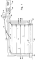
- FIG. 1 is a partially perspective and partially schematic view of a door operator system according to the invention.
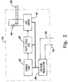
- FIG. 2 is block diagram of the coded light transmitter of FIG. 1.
- FIG. 3 is a block diagram of the light receiver of FIG. 1.
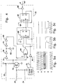
- FIG. 4 is a schematic diagram of the control signal detector of FIG. 1.
- FIG. 5a is an exemplary graph showing the interrelationship between the signals at indicated points in FIG. 4 when coded light is being received.
- FIG. 5b is an exemplary graph showing the interrelationship between the signals at indicated points in FIG. 4 when coded light is not being received or various error conditions exist.
- FIG. 5c is an exemplary graph showing the interrelationship between the signals at indicated points in FIG. 4 when various other error conditions exist.
- Referring to FIG. 1, a
door operator 12 is connected to adoor 14 by anarm 16. Theaim 16 is driven along atrack 18 by anelectric motor 20, resulting in thedoor 14 either opening or closing, depending the direction of travel of thearm 16. - A
control circuit 22 determines the direction of travel, if any, of thearm 16. - A coded
light transmitter 24 is located at one side of thedoor 14, near thethreshold 26. Alight receiver 28 is located at the opposite side of thedoor 14, near thethreshold 26. - The
transmitter 24 and thereceiver 28 are connected to acontrol signal detector 30 by asupply wire 32, and aground wire 34. In addition, thereceiver 28 is connected to thecontrol signal detector 30 by acontrol signal wire 36. - The
control circuit 22 and thecontrol circuit detector 30 are both located remotely from thethreshold 26. Thecontrol signal detector 30 may be advantageously housed commonly with thecontrol circuit 22 or located close by. - In the preferred embodiment, the
transmitter 24, thereceiver 28 and thecontrol signal detector 30, all receive power from thecontrol circuit 22 which may supply, for example, 24 volts d.c. Thetransmitter 24 and thereceiver 28 are supplied with power by thewires - Referring to FIG. 2, the
transmitter 24 includes avoltage regulator 38 connected to thesupply wire 32 and theground wire 34. Theregulator 38 provides regulated power (e.g. 12 volts d.c.) to power a duty-cycle oscillator 40, acoding oscillator 42 and anLED driver 44. - The
coding oscillator 42 provides a gating signal to the duty-cycle oscillator 40. The duty-cycle oscillator 40 provides a high frequency (e.g., 10 KHz) pulse train gated by the grating signal to theLED driver 44. TheLED driver 44 in turn drives aninfrared LED 46 to supply the coded light beam 88 (see FIG. 1). - The duty cycle of the pulses from the duty-
cycle oscillator 40 is chosen to allow maintenance of sufficient intensity of the codedlight beam 48 to overcome ambient light while keeping theLED driver 44 power dissipation below safe levels. For example, a duty cycle of 25% may be used. The high frequency of the pulses facilitates the reception of the codedlight beam 48. - The frequency and duty cycle of the
coding oscillator 42 is chosen to provide a suitable code for the codedlight beam 48. For example, a frequency of 50 Hz and a 50% duty cycle may be used. This results in the codedlight beam 48 being made up of 10 millesecond packets of 10 kHz light pulses followed by 10 milliseconds of no pulses, repeating 50 times per second. - Referring to FIG. 3, the
receiver 28 includes avoltage regulator 50 connected to thesupply wire 32 and theground wire 34. Theregulator 50 provides regulated power (e.g. 12 volts d.c.) to power abuffer 68, an integrated-circuit detector 52 and ahigh pass filter 54. - The coded
light beam 48 is focused by alens 58 on aninfrared photodiode 60. The coded light beam passes through aninfrared filter 56 that blocks the majority of ambient light (non-infrared), before contactingphotodiode 60. - The
high pass filter 54 is chosen so that the desired signal (e.g. 10 khz) will be passed, while most ambient light produced voltage (which has very little high frequency content) is blocked. - The signal from the
high pass filter 54 passes to the integrated-circuit detector 52. The integrated-circuit detector 52 contains anamplifier 62, afilter 64 and adetector 66 optimized to detect the envelope of a high frequency pulse train (e.g. a 10 kHz pulse train) and provide the envelope as an output, which in the present example would be a 50 Hz square wave. - The output of the integrated-
circuit detector 52 passes to the input of abuffer 68 where it is buffered and provided as a control signal on thecontrol signal wire 36. - The output of the integrated-
circuit detector 52 provides a visual indication that it is receiving the codedlight beam 48 by energizing avisible light LED 69. - Referring to FIG.4, the
control signal detector 30 is provided with a voltage V⁺ which may be advantageously obtained from the control circuit 22 (see FIG. 1). A clock signal 70 (e.g. 60 Hz) may be obtained also from thecontrol circuit 22 or generated locally. - The control signal from the
control signal wire 36 is buffered by the npn-transistor 72. The buffered control signal is applied to a delay circuit composed in this example of a series ofinverters capacitor 82 connected between theinverters inverter 80. The buffered control signal and the delayed control signal are applied to respective inputs of an "exclusive or"gate 84. - The output of the "exclusive or"
gate 84 is applied to the reset inputs "R" of a pair of flip-flops - The
clock signal 70 is inverted by aninverter 90 and applied to the clock pulse input "CP" of the flip-flop 86. - The inverted output "Q" of the flip-
flop 86 is applied to the "D" input of the flip-flop 86 and to the clock pulse input "CP" of the flip-flop 88. - The inverted output "Q" of the flip-
flop 88 is applied to the "D" input of the flip-flop 88. - The set terminals "S" of both flip-
flops - The output "Q" of the flip-
flop 88 is inverted by aninverter 89 to provide a "safe"/"unsafe"signal 92 to thecontrol circuit 22. - The flip-
flops gate 84 will reset them, resulting in a high output for the "safe"/"unsafe"signal 92. On the other hand, a low value from thegate 84 will result in clock pulses from theclock signal 70 rippling down through the flip-flops signal 92. - In normal operation, the
transmitter 24 transmits the codedlight beam 48 composed of packets of light pulses towards thereceiver 28. - If no obstruction prevents the coded
light beam 48 from reaching thereceiver 28, thereceiver 28 detects the envelope of the codedlight beam 48 and provides the resulting coded control signal in the form of a square wave to thecontrol signal detector 30 via thecontrol signal wire 36. - The control signal and a delayed version of the control signal are applied to the "exclusive or"
gate 84. The output of thegate 84 for these square wave inputs is a pulsed wave, the pulse duration being equal to the delay between the control signal and the delayed version of the control signal. This is shown in FIG. 5a for signal C, the output of thegate 84, (signal B being the control signal and signal A being the delayed control signal). The output of thegate 84 continuously resets the flip-flops flops signal 92 stays high (signal D), thus providing the control circuit 22 a "safe" signal. - In response to "safe" signals, the
control circuit 22 operates to raise and lower the door upon command. - If an obstruction prevents the coded
light beam 48 from reaching thereceiver 28, a control signal without coding is provided by thereceiver 28 to thecontrol signal detector 30. - Without the coding, the control signal is essentially constant with respect the
clock signal 70. As shown in FIG. 5b, the control signal B and the delayed control signal A are the same, thus the output of thegate 84 is a constant low value (signal C). This constant output of thegate 84 does not reset the flip-flops flops signal 92, thus providing thecontrol circuit 22 with an "unsafe" signal. - In response to "unsafe" signals, the
control circuit 22 reverses thedoor 14 if it is closing, continues opening thedoor 14 if it is opening, and prevents thedoor 14 from closing if it is up. - In addition, in the present invention, if the
signal wire 36 becomes disconnected or shorted to ground, the signals will also appear as in FIG. 5b. - Similarly, if the
signal wire 36 is shorted to the supply voltage (through a short to thesupply wire 32 or some other malfunction), the signals will appear as in FIG. 5c, where the output of the gate 84 (signal C) is still low and thus thecontrol circuit 22 will receive an "unsafe" signal. - Also, since the
receiver 28 has no internal source for the coded control signal (all coding being provided by the transmitter 24), if thereceiver 28 fails, its output can not be the coded control signal and hence either the case of FIG. 5b or FIG. 5c will result and an "unsafe" signal will be sent to the control circuit. - Of course, if the
transmitter 24 malfunctions, the effect will be the same as if an obstruction blocked thelight beam 48. - It should be noted that while an optical obstruction detector is described, it would also be possible to practice the invention with other wave based obstruction detectors, such as radio-wave or sound-wave obstruction detectors wherein the wave is coded to distinguish it from error conditions. Also, other means of coding or modulating the control signal could be employed, as long as detected signal could be distinguished from the signals produced in response to obstructions, wiring errors or malfunctions.
- While not the preferred embodiment, it would also be possible to utilize a coded signal with other obstruction detectors. For example, an edge detector with normally-closed switches in series could replace the wave path between the coded signal source and the receiver. This would effectively substitute the direct blocking of a wave by an obstruction for the indirect interruption of the coded signal by the physical operation of the switches. Because the transmitted signal would not be electrically isolated from the receiver, failure or fault detection would suffer, but most conditions would still be detected. In particular, shorts, opens or errors in the wiring between the coded signal source, the receiver and the control signal detector would be detected.
- It should be evident that this disclosure is by way of example and that various changes may be made by adding, modifying or eliminating details without departing from the fair scope of the teaching contained in this disclosure. The invention is therefore not limited to particular details of this disclosure except to the extent that the following claims are necessarily so limited.
Claims (12)
- A door operator system comprising:
control means for controlling the opening and closing of a door across a door threshold;
a coded wave transmitter for providing a coded wave;
a wave receiver for providing a coded control signal in response to receipt of said coded wave, the presence of an obstruction in said door threshold preventing said receipt; and
control signal detection means for detecting said coded control signal and providing an "unsafe" signal to said control means if no coded control signal is detected. - A door operator system according to claim 1, wherein said wave is an optical wave.
- A door operator system according to claim 1, wherein said wave is an infrared wave.
- A door operator system according to claim 1, wherein said coded wave comprises packets of wave pulses.
- A door operator system according to claim 1, wherein said control signal detection means comprises means to delay said coded control signal to provide a delayed signal and means to "exclusive or" said coded control signal and said delayed signal to provide said "unsafe" signal.
- A door operator system comprising:
control means for controlling the opening and closing of a door across a door threshold, said control means being adapted to be located remotely from said threshold;
source means for providing a coded signal, said source means being adapted to be located proximately to said threshold;
interruption means for interrupting said coded signal in the presence of an obstruction in said threshold;
receiver means for providing a coded control signal indicative of said interruption, said receiver means being adapted to be located proximately to said threshold; and
control signal detection means for detecting said coded control signal and providing an "unsafe" signal to said control means if said coded control signal is not detected, said detection means being adapted to be located proximately to said control means. - A door operator system according to claim 6, wherein said coded signal is a light beam and said interruption means comprises said obstruction blocking said light beam from said receiver means.
- A door operator system according to claim 6, wherein said coded signal is an infrared beam and said interruption means comprises said obstruction blocking said infrared beam from said receiver means.
- A door operator system according to claim 6, wherein said coded signal comprises packets of light pulses.
- A door operator system according to claim 6, further comprising a control housing containing both said control signal detection means and said control means.
- A door operator system according to claim 6, wherein said control signal detection means comprises means to delay said coded control signal to provide a delayed signal and means to "exclusive or" said coded control signal and said delayed signal to provide said "unsafe" signal.
- A door operator system comprising:
control means for controlling the opening and closing of a door across a door threshold, said control means being located remotely from said threshold;
a coded light beam transmitter located proximately to a first side of said threshold, said transmitter providing a light beam of packets of light pulses and being powered from said control means, said packets having a period;
a coded light beam receiver located proximately to a second side of said threshold, said receiver providing a control signal having said period when said coded light beam is received by said receiver and being powered from said control means, the presence of an obstruction preventing the receipt of said coded light beam;
control signal detection means having means to delay said control signal to provide a delayed signal and means to "exclusive or" said control signal and said delayed signal to provide an "unsafe" signal to said control means, said detection means being located proximately to said control means and said detection means, said transmitter and said receiver being powered from said control means.
Applications Claiming Priority (2)
| Application Number | Priority Date | Filing Date | Title |
|---|---|---|---|
| US66004291A | 1991-02-25 | 1991-02-25 | |
| US660042 | 1991-02-25 |
Publications (3)
| Publication Number | Publication Date |
|---|---|
| EP0501858A2 true EP0501858A2 (en) | 1992-09-02 |
| EP0501858A3 EP0501858A3 (en) | 1993-03-31 |
| EP0501858B1 EP0501858B1 (en) | 1996-11-13 |
Family
ID=24647887
Family Applications (1)
| Application Number | Title | Priority Date | Filing Date |
|---|---|---|---|
| EP92400458A Expired - Lifetime EP0501858B1 (en) | 1991-02-25 | 1992-02-21 | Fail safe obstruction detector for door openers |
Country Status (4)
| Country | Link |
|---|---|
| EP (1) | EP0501858B1 (en) |
| AT (1) | ATE145303T1 (en) |
| CA (1) | CA2057650C (en) |
| DE (1) | DE69215127T2 (en) |
Cited By (3)
| Publication number | Priority date | Publication date | Assignee | Title |
|---|---|---|---|---|
| EP0803632A1 (en) * | 1996-04-26 | 1997-10-29 | Nabco Limited | Door sensor with self-diagnosing function |
| EP0809163A3 (en) * | 1996-05-17 | 1999-07-28 | Nabco Limited | Automatic door system with self-diagnosing function |
| DE102012104750A1 (en) * | 2012-06-01 | 2013-12-05 | Ingo Reusch | Device for contact-free opening of door in public toilet, has sensor device generating signal during non-contact approach of human hand, where signal is provided to activate electrical motor for opening door for predetermined time interval |
Family Cites Families (2)
| Publication number | Priority date | Publication date | Assignee | Title |
|---|---|---|---|---|
| DE2007840C3 (en) * | 1970-02-20 | 1979-11-15 | Endl, Alfons, 8000 Muenchen | Light barrier |
| DE9006605U1 (en) * | 1990-06-12 | 1990-08-16 | Brinkmann, Heinz-Jürgen, 4322 Sprockhövel | Circuit monitoring on movable closing edges |
-
1991
- 1991-12-13 CA CA002057650A patent/CA2057650C/en not_active Expired - Lifetime
-
1992
- 1992-02-21 EP EP92400458A patent/EP0501858B1/en not_active Expired - Lifetime
- 1992-02-21 AT AT92400458T patent/ATE145303T1/en active
- 1992-02-21 DE DE69215127T patent/DE69215127T2/en not_active Expired - Lifetime
Cited By (4)
| Publication number | Priority date | Publication date | Assignee | Title |
|---|---|---|---|---|
| EP0803632A1 (en) * | 1996-04-26 | 1997-10-29 | Nabco Limited | Door sensor with self-diagnosing function |
| US5828302A (en) * | 1996-04-26 | 1998-10-27 | Tsutsumi; Koji | Door sensor with self-diagnosing function |
| EP0809163A3 (en) * | 1996-05-17 | 1999-07-28 | Nabco Limited | Automatic door system with self-diagnosing function |
| DE102012104750A1 (en) * | 2012-06-01 | 2013-12-05 | Ingo Reusch | Device for contact-free opening of door in public toilet, has sensor device generating signal during non-contact approach of human hand, where signal is provided to activate electrical motor for opening door for predetermined time interval |
Also Published As
| Publication number | Publication date |
|---|---|
| ATE145303T1 (en) | 1996-11-15 |
| DE69215127D1 (en) | 1996-12-19 |
| EP0501858B1 (en) | 1996-11-13 |
| EP0501858A3 (en) | 1993-03-31 |
| CA2057650C (en) | 1998-10-13 |
| DE69215127T2 (en) | 1997-05-22 |
| CA2057650A1 (en) | 1992-08-26 |
Similar Documents
| Publication | Publication Date | Title |
|---|---|---|
| US5428923A (en) | Fail safe obstruction detector for door operators and door operator system incorporating such detector | |
| US5191268A (en) | Continuously monitored supplemental obstruction detector for garage door operator | |
| US4821024A (en) | Door operator pre-warning system | |
| US5656900A (en) | Retro-reflective infrared safety sensor for garage door operators | |
| US4922168A (en) | Universal door safety system | |
| US5247232A (en) | Automatic garage door control device | |
| US5684372A (en) | Garage door operator safety apparatus | |
| US6169379B1 (en) | Power driven venting of a vehicle | |
| EP0557589B1 (en) | Light beam detector for door openers using fiber optics | |
| EP0803632B1 (en) | Door sensor with self-diagnosing function | |
| US4560912A (en) | Object sensing apparatus for an automatic door | |
| US5412297A (en) | Monitored radio frequency door edge sensor | |
| US20030154656A1 (en) | Barrier movement control safety method and apparatus | |
| US20010042820A1 (en) | Optoelectronic system for an automatic vehicle door closure | |
| CA2059802C (en) | Wiring error detector for door operator | |
| US5569910A (en) | Photodetector system for detecting obstacles in aisles between mobile shelving carriages | |
| MXPA02007362A (en) | Safety interlock for mechanically actuated closure device. | |
| EP0501858B1 (en) | Fail safe obstruction detector for door openers | |
| JPH07507116A (en) | Vehicle power-driven opening/closing device | |
| MXPA02004858A (en) | Integrated obstacle detection system. | |
| EP1248710A1 (en) | Safety system | |
| WO1994008120A1 (en) | Improved obstruction detection system for a vehicle window | |
| JPH0533552A (en) | Touch switch for automatic door |
Legal Events
| Date | Code | Title | Description |
|---|---|---|---|
| PUAI | Public reference made under article 153(3) epc to a published international application that has entered the european phase |
Free format text: ORIGINAL CODE: 0009012 |
|
| AK | Designated contracting states |
Kind code of ref document: A2 Designated state(s): AT DE FR GB IT |
|
| PUAL | Search report despatched |
Free format text: ORIGINAL CODE: 0009013 |
|
| AK | Designated contracting states |
Kind code of ref document: A3 Designated state(s): AT DE FR GB IT |
|
| 17P | Request for examination filed |
Effective date: 19930910 |
|
| 17Q | First examination report despatched |
Effective date: 19950210 |
|
| GRAG | Despatch of communication of intention to grant |
Free format text: ORIGINAL CODE: EPIDOS AGRA |
|
| GRAH | Despatch of communication of intention to grant a patent |
Free format text: ORIGINAL CODE: EPIDOS IGRA |
|
| GRAH | Despatch of communication of intention to grant a patent |
Free format text: ORIGINAL CODE: EPIDOS IGRA |
|
| GRAA | (expected) grant |
Free format text: ORIGINAL CODE: 0009210 |
|
| AK | Designated contracting states |
Kind code of ref document: B1 Designated state(s): AT DE FR GB IT |
|
| REF | Corresponds to: |
Ref document number: 145303 Country of ref document: AT Date of ref document: 19961115 Kind code of ref document: T |
|
| REF | Corresponds to: |
Ref document number: 69215127 Country of ref document: DE Date of ref document: 19961219 |
|
| ITF | It: translation for a ep patent filed | ||
| ET | Fr: translation filed | ||
| PLBE | No opposition filed within time limit |
Free format text: ORIGINAL CODE: 0009261 |
|
| STAA | Information on the status of an ep patent application or granted ep patent |
Free format text: STATUS: NO OPPOSITION FILED WITHIN TIME LIMIT |
|
| 26N | No opposition filed | ||
| REG | Reference to a national code |
Ref country code: GB Ref legal event code: IF02 |
|
| PG25 | Lapsed in a contracting state [announced via postgrant information from national office to epo] |
Ref country code: IT Free format text: LAPSE BECAUSE OF NON-PAYMENT OF DUE FEES Effective date: 20080221 |
|
| PGFP | Annual fee paid to national office [announced via postgrant information from national office to epo] |
Ref country code: DE Payment date: 20110228 Year of fee payment: 20 Ref country code: AT Payment date: 20110223 Year of fee payment: 20 Ref country code: FR Payment date: 20110302 Year of fee payment: 20 |
|
| PGFP | Annual fee paid to national office [announced via postgrant information from national office to epo] |
Ref country code: GB Payment date: 20110216 Year of fee payment: 20 Ref country code: IT Payment date: 20110228 Year of fee payment: 20 |
|
| PGRI | Patent reinstated in contracting state [announced from national office to epo] |
Ref country code: IT Effective date: 20110616 |
|
| REG | Reference to a national code |
Ref country code: DE Ref legal event code: R071 Ref document number: 69215127 Country of ref document: DE |
|
| REG | Reference to a national code |
Ref country code: DE Ref legal event code: R071 Ref document number: 69215127 Country of ref document: DE |
|
| REG | Reference to a national code |
Ref country code: GB Ref legal event code: PE20 Expiry date: 20120220 |
|
| PG25 | Lapsed in a contracting state [announced via postgrant information from national office to epo] |
Ref country code: DE Free format text: LAPSE BECAUSE OF EXPIRATION OF PROTECTION Effective date: 20120222 |
|
| PG25 | Lapsed in a contracting state [announced via postgrant information from national office to epo] |
Ref country code: GB Free format text: LAPSE BECAUSE OF EXPIRATION OF PROTECTION Effective date: 20120220 |
|
| REG | Reference to a national code |
Ref country code: AT Ref legal event code: MK07 Ref document number: 145303 Country of ref document: AT Kind code of ref document: T Effective date: 20120221 |