EP0501372B1 - Container holder - Google Patents
Container holder Download PDFInfo
- Publication number
- EP0501372B1 EP0501372B1 EP92103056A EP92103056A EP0501372B1 EP 0501372 B1 EP0501372 B1 EP 0501372B1 EP 92103056 A EP92103056 A EP 92103056A EP 92103056 A EP92103056 A EP 92103056A EP 0501372 B1 EP0501372 B1 EP 0501372B1
- Authority
- EP
- European Patent Office
- Prior art keywords
- container
- holder
- container holding
- holder body
- center
- Prior art date
- Legal status (The legal status is an assumption and is not a legal conclusion. Google has not performed a legal analysis and makes no representation as to the accuracy of the status listed.)
- Expired - Lifetime
Links
- 230000001788 irregular Effects 0.000 description 1
- 238000004519 manufacturing process Methods 0.000 description 1
- 239000011347 resin Substances 0.000 description 1
- 229920005989 resin Polymers 0.000 description 1
Images


Classifications
-
- B—PERFORMING OPERATIONS; TRANSPORTING
- B65—CONVEYING; PACKING; STORING; HANDLING THIN OR FILAMENTARY MATERIAL
- B65B—MACHINES, APPARATUS OR DEVICES FOR, OR METHODS OF, PACKAGING ARTICLES OR MATERIALS; UNPACKING
- B65B59/00—Arrangements to enable machines to handle articles of different sizes, to produce packages of different sizes, to vary the contents of packages, to handle different types of packaging material, or to give access for cleaning or maintenance purposes
- B65B59/003—Arrangements to enable adjustments related to the packaging material
-
- B—PERFORMING OPERATIONS; TRANSPORTING
- B65—CONVEYING; PACKING; STORING; HANDLING THIN OR FILAMENTARY MATERIAL
- B65G—TRANSPORT OR STORAGE DEVICES, e.g. CONVEYORS FOR LOADING OR TIPPING, SHOP CONVEYOR SYSTEMS OR PNEUMATIC TUBE CONVEYORS
- B65G17/00—Conveyors having an endless traction element, e.g. a chain, transmitting movement to a continuous or substantially-continuous load-carrying surface or to a series of individual load-carriers; Endless-chain conveyors in which the chains form the load-carrying surface
- B65G17/002—Conveyors having an endless traction element, e.g. a chain, transmitting movement to a continuous or substantially-continuous load-carrying surface or to a series of individual load-carriers; Endless-chain conveyors in which the chains form the load-carrying surface comprising load carriers resting on the traction element
-
- Y—GENERAL TAGGING OF NEW TECHNOLOGICAL DEVELOPMENTS; GENERAL TAGGING OF CROSS-SECTIONAL TECHNOLOGIES SPANNING OVER SEVERAL SECTIONS OF THE IPC; TECHNICAL SUBJECTS COVERED BY FORMER USPC CROSS-REFERENCE ART COLLECTIONS [XRACs] AND DIGESTS
- Y10—TECHNICAL SUBJECTS COVERED BY FORMER USPC
- Y10T—TECHNICAL SUBJECTS COVERED BY FORMER US CLASSIFICATION
- Y10T279/00—Chucks or sockets
- Y10T279/12—Chucks or sockets with fluid-pressure actuator
- Y10T279/1274—Radially reciprocating jaws
- Y10T279/1283—Fluid pressure directly moves jaws
-
- Y—GENERAL TAGGING OF NEW TECHNOLOGICAL DEVELOPMENTS; GENERAL TAGGING OF CROSS-SECTIONAL TECHNOLOGIES SPANNING OVER SEVERAL SECTIONS OF THE IPC; TECHNICAL SUBJECTS COVERED BY FORMER USPC CROSS-REFERENCE ART COLLECTIONS [XRACs] AND DIGESTS
- Y10—TECHNICAL SUBJECTS COVERED BY FORMER USPC
- Y10T—TECHNICAL SUBJECTS COVERED BY FORMER US CLASSIFICATION
- Y10T279/00—Chucks or sockets
- Y10T279/19—Radially reciprocating jaws
Definitions
- the invention relates to a container holder as may be used in a variety of container processing steps such as a filling operation or a capping operation, and in particular, to a container holder which is commonly referred to as "skirt", which is used to hold a container by a fitting engagement with a container in order to position such containers.
- such a container holder is generally formed as a body molded from a resin which is provided with a receiving opening conforming to the configuration of a specific container. Accordingly, a particular holder cannot be used with containers of a different kind. If a plurality of container receiving openings are formed in the body in a manner such that cross-sectional configurations of different containers cross each other, in actual practice, a single holder can be used with at most two kinds of containers.
- a container holder according to the preamble of Claim 1 is known from US-A-3248120.
- This known apparatus comprises a plurality of jaws reciprocally mounted within a holder body.
- the jaws are moved by means of control means to be positioned with respect to the container within the holder body such that they are all equidistant from the center of the holder body to securely fix the container in position.
- the jaws are spring-mounted to allow a minimal flexibility of their position with respect to the container and thus accommodate slight variances in tolerance and possible slight deformation in the shape of the container during processing while being held in the container holder.
- a prefered embodiment of the inventive container holder comprises a holder body which receives a container at the center of the holder body, four container holding members disposed within the holder body, one pair being oppositely disposed on one of orthogonal lines passing through the center of the holder body, advance means for individually advancing each container holding member toward the center of the holder body, stop means for stopping each container holding member independently as it has been advanced to a given position, and retraction means for retracting the container holding members toward the outside of the holder body.
- a tubular casing (holder body) 2 having a rectangular cross section and having a closed bottom are four container holding members 4a, 4b, 4c and 4d in a reciprocable manner.
- the casing 2 is substantially in the form of a square in section, and the four corners are cut off and replaced by arcs of a circle to present generally a substantially octagonal configuration.
- the receptacle 6 is formed with a pair of cylinder openings 6a, 6b which are disposed on the opposite sides of a bisector line Y, passing through the center O1 of the container holder and dividing the interior of the holder into two equal portions, and which extend from opposite or upper and lower sidewalls 2a, 2b of the casing toward and beyond the center in parallel relationship with the line Y.
- a pair of cylinder openings 6c, 6d are disposed on the opposite sides of a line X which is perpendicular to the line Y and extend from the opposite lateral sidewalls 2c, 2d of the casing toward and beyond the center of the casing in parallel relationship with the line X.
- Each of the four cylinder openings 6a, 6b, 6c and 6d extend beyond the center of the container receptacle 6, but each opposing pair runs parallel to each line X or Y on opposite sides thereof, and one pair is located at a different elevation from the other pair, so that they cannot intercept with each other within the receptacle.
- Pin cylinders 8a, 8b, 8c and 8d are slidably fitted in the cylinder openings 6a, 6b, 6c and 6d, respectively.
- the container holding members 4a, 4b, 4c and 4d are fixedly mounted on the respective pin cylinders 8a, 8b, 8c and 8d, respectively.
- Elongate slots 10a, 10b, 10c and 10d are formed in the receptacle 6 at respective locations above the associated cylinder openings 6a, 6b, 6c and 6d, respectively, and extend to the upper surface of the receptacle 6, whereby the container holding members 4a, 4b, 4c and 4d are reciprocable with the pin cylinders 8a, 8b, 8c and 8d, respectively, within an extent defined by these elongate slots 10a, 10b, 10c and 10d, respectively.
- O-rings 9a, 9b, 9c and 9d are fitted over the free end of the pin cylinders, 8a, 8b, 8c and 8d, respectively, and their friction is effective to prevent a movement of the associated pin cylinder when the latter is inoperative.
- a recess 2e is centrally formed in the upper surface of the bottom of the casing 2, and the container receptacle 6 is formed with air passages 12a, 12b, 12c and 12d (12a and 12b being not shown) which provide a communication between the recess 2e and the inner tip end of the respective cylinder openings 6a, 6b, 6c and 6d.
- the bottom of the casing 2 is formed with a supply port 2f through which the air is introduced into the recess 2e from the outside.
- container model or remodelling jig is inserted inside the four container holding members 4a, 4b, 4c and 4d, and four remodelling push pins 16 are inserted into the respective cylinder openings 6a, 6b, 6c and 6d, and the pin cylinders 8a, 8b, 8c and 8d are driven inward until the associated container holding members 4a, 4b, 4c and 4d move into abutment against the respective container models.
- Such movement of the container holding members 4a, 4b, 4c and 4d in conformity to the container model allows a container of any configuration to be held in a stable manner within the space defined by the four container holding members.
- a container holder comprises a holder body 20, and two pairs of fingers or container holding members 22, 24, the fingers of each pair being disposed in opposing relationship to each other on one of orthogonal lines X or Y which passes through the center O2 of the holder body 20.
- Each finger 22 or 24 is reciprocable on the associated line X or Y, and the opposing surfaces are formed with V-shaped recesses 22a, 24a.
- the rear surface of each finger 22, 24 is formed with a slot 22b or 24b (22b being not shown) (see Fig. 4) which receives a transversely elongate T-shaped jig 44 (see Fig. 3).
- each finger 22, 24 is formed with a number of teeth 22c, 24c, and ratchets 26, 28 are disposed laterally adjacent to the finger teeth 22c, 24c for meshing engagement with their teeth.
- Each ratchet 26, 28 is rotatable about a fulcrum pin 30, 32, but is urged by an associated spring 34 or 36 which engages their rear surface into meshing engagement with the associated finger teeth 22c or 24c.
- the meshing engagement between the finger teeth 22c, 24c and the ratchet 26, 28 prevents a movement of the finger teeth 22c, 24c toward the center of the holder 20, but the tooth configuration may be modified to provide a stop in either direction. As shown in Fig.
- the ratchet 26, 28 comprises a plurality of divided sections for the purpose of assuring a meshing engagement of teeth in any one of these sections with the finger teeth 22c, 24c as a result of slight differences in the sizes of the individual sections.
- Anti-rattling brakes 38, 40 (38 being not shown) are disposed intermediate the upper two and the lower two sections of the ratchets 26, 28, but may be dispensed with under certain instances.
- a top cover 42 is secured around the outer periphery of the holder body 20, and is formed with four circular holes 42a at locations directly above the ratchet 26, 28.
- the ratchets 26, 28 are formed with circular holes 26a, 28a of a reduced diameter at a position which is eccentric from the circular hole 42a when the ratchets are urged by the springs 34, 36 into meshing engagement with the finger teeth 22c, 24c.
- T-shaped jig 44 (see Fig. 3) is inserted through the transversely elongate slot 22b, 24b formed in the rear surface of each finger 22, 24 at the home station, and then is rotated to engage it with the inner surface of the opening 22b, 24b to allow the fingers 22, 24 to be pulled to return them to their start position (where the fingers 22, 24 have retracted through its full extent).
- a pin 46 having a tapered tip is inserted through the circular hole 42a in the top cover 42 and the hole 26a or 28a of a smaller diameter of either ratchet 26 or 28 which is disposed eccentric with respect to the circular hole 42a to disengage the ratchet 26 or 28 from the teeth 22c or 24c.
- a container model is disposed into the central portion of the holder body 20, and subsequently the fingers 22, 24 are driven toward the center until they contact the container model.
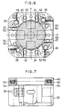
- Figs. 6 and 7 show a third embodiment of the invention.
- This embodiment includes fingers 22, 24 and ratchets 26, 28 which serve as stops for the fingers 22, 24, all of which are similar to those of the previous embodiment.
- this embodiment includes a mechanism for preventing any movement of the fingers 22, 24 upon impact.
- the top cover 42 houses springs 50, 52 at locations directly above the respective fingers 22, 24 and these springs act to urge the associated fingers 22, 24 against the bottom surface of the holder body 20 through abutments 54, 56.
- a remodelling operation of this embodiment takes place in the similar manner as in the second embodiment.
Landscapes
- Engineering & Computer Science (AREA)
- Mechanical Engineering (AREA)
- Filling Of Jars Or Cans And Processes For Cleaning And Sealing Jars (AREA)
- Supplying Of Containers To The Packaging Station (AREA)
Description
- The invention relates to a container holder as may be used in a variety of container processing steps such as a filling operation or a capping operation, and in particular, to a container holder which is commonly referred to as "skirt", which is used to hold a container by a fitting engagement with a container in order to position such containers.
- In a variety of processing operations such as a filling or a capping operation to be applied to containers having a varied cross sectional configuration such as an elliptical cross section, the orientation or centering of containers has been conducted by fitting containers in a container holder as mentioned above before they are placed on a processing line.
- However, such a container holder is generally formed as a body molded from a resin which is provided with a receiving opening conforming to the configuration of a specific container. Accordingly, a particular holder cannot be used with containers of a different kind. If a plurality of container receiving openings are formed in the body in a manner such that cross-sectional configurations of different containers cross each other, in actual practice, a single holder can be used with at most two kinds of containers.
- Where many varieties of containers are to be treated, a number of container holders must be manufactured if the prior practice is followed. In addition, a number of difficulties have been experienced with space for storage of the holders and their placement onto a processing line.
- A container holder according to the preamble of Claim 1 is known from US-A-3248120. This known apparatus comprises a plurality of jaws reciprocally mounted within a holder body. The jaws are moved by means of control means to be positioned with respect to the container within the holder body such that they are all equidistant from the center of the holder body to securely fix the container in position. Additionally, the jaws are spring-mounted to allow a minimal flexibility of their position with respect to the container and thus accommodate slight variances in tolerance and possible slight deformation in the shape of the container during processing while being held in the container holder.
- Accordingly, it is an object of the invention to provide a container holder which simple in structure and cheap to manufacture and simultaneously useable with a variety of regular or irregular shapes of containers in common.
- This object is solved according to the present invention by a container holder including the features of claim 1.
- A prefered embodiment of the inventive container holder comprises a holder body which receives a container at the center of the holder body, four container holding members disposed within the holder body, one pair being oppositely disposed on one of orthogonal lines passing through the center of the holder body, advance means for individually advancing each container holding member toward the center of the holder body, stop means for stopping each container holding member independently as it has been advanced to a given position, and retraction means for retracting the container holding members toward the outside of the holder body.
- Fig. 1 is a plan view of a container holder according to one embodiment of the invention;
- Fig. 2 is a longitudinal section of the container holder;
- Fig. 3 is a plan view of a container holder according to a second embodiment of the invention;
- Fig. 4 is a side elevation, partly in section, of the container holder of the second embodiment;
- Fig. 5 is an illustration of disengaging a ratchet;
- Fig. 6 is a plan view of a container holder according to a third embodiment of the invention; and
- Fig. 7 is a side elevation, partly in section, of the container holder of the third embodiment.
- Several embodiments of the invention will now be described with reference to the drawings. Disposed in a tubular casing (holder body) 2 having a rectangular cross section and having a closed bottom are four
container holding members - The
casing 2 is substantially in the form of a square in section, and the four corners are cut off and replaced by arcs of a circle to present generally a substantially octagonal configuration. Acontainer receptacle 6, having openings to be fitted by pin cylinder to be described later, an air passage or the like, is placed on and secured to the bottom. In its upper portion, thereceptacle 6 is formed with a pair ofcylinder openings lower sidewalls cylinder openings cylinder openings lateral sidewalls cylinder openings container receptacle 6, but each opposing pair runs parallel to each line X or Y on opposite sides thereof, and one pair is located at a different elevation from the other pair, so that they cannot intercept with each other within the receptacle.Pin cylinders cylinder openings container holding members respective pin cylinders slots receptacle 6 at respective locations above the associatedcylinder openings receptacle 6, whereby thecontainer holding members pin cylinders elongate slots rings 9a, 9b, 9c and 9d are fitted over the free end of the pin cylinders, 8a, 8b, 8c and 8d, respectively, and their friction is effective to prevent a movement of the associated pin cylinder when the latter is inoperative. - A
recess 2e is centrally formed in the upper surface of the bottom of thecasing 2, and thecontainer receptacle 6 is formed withair passages recess 2e and the inner tip end of therespective cylinder openings casing 2 is formed with asupply port 2f through which the air is introduced into therecess 2e from the outside. - A remodelling of the container holder, namely, an adjustment to be made to cause the holder to adapt to a different container configuration, will now be described. At a home station on a line on which the container holder is conveyed, an air coupler 14 (see Fig. 2) is inserted into the
air supply port 2f in the bottom surface of thecasing 2, and the air pressure is utilized to cause thepin cylinders cylinder openings container holding members sidewalls container holding members push pins 16 are inserted into therespective cylinder openings pin cylinders container holding members - Such movement of the
container holding members - Referring to Figs. 3 to 5, a second embodiment of the invention will now be described. In this instance, a container holder comprises a
holder body 20, and two pairs of fingers orcontainer holding members holder body 20. Eachfinger shaped recesses finger slot 22b or 24b (22b being not shown) (see Fig. 4) which receives a transversely elongate T-shaped jig 44 (see Fig. 3). - One lateral surface of each
finger teeth ratchets finger teeth ratchet fulcrum pin spring finger teeth finger teeth ratchet finger teeth holder 20, but the tooth configuration may be modified to provide a stop in either direction. As shown in Fig. 4, theratchet finger teeth ratchets - A
top cover 42 is secured around the outer periphery of theholder body 20, and is formed with fourcircular holes 42a at locations directly above theratchet ratchets circular holes circular hole 42a when the ratchets are urged by thesprings finger teeth - In operation, T-shaped jig 44(see Fig. 3) is inserted through the transversely
elongate slot 22b, 24b formed in the rear surface of eachfinger fingers fingers - At a remodelling station, a
pin 46 having a tapered tip (see Fig. 5) is inserted through thecircular hole 42a in thetop cover 42 and thehole ratchet circular hole 42a to disengage theratchet teeth holder body 20, and subsequently thefingers - Figs. 6 and 7 show a third embodiment of the invention. This embodiment includes
fingers ratchets fingers fingers top cover 42 houses springs 50, 52 at locations directly above therespective fingers fingers holder body 20 throughabutments
Claims (10)
- A container holder comprising a holder body (2, 20) for receiving a container at the center of the holder body, a plurality of container holding members (4, 22, 24) which are reciprocally actuatable towards and away from the center of the holder body (2, 20), advance means for advancing the container holding members (4, 22, 24) to a selected container holding position towards the center of the holder body (2, 20), and retraction means for retracting the container holding members from said holding position, wherein each container holding member (4, 22, 24) is provided with a separate stopping means (9, 26, 28) to maintain said holding members at a selected holding position with respect to the center of the holder body (2, 20), characterized in that the stopping means (9, 26, 28) of each container holding member (4, 22, 24) is selectively adjustable such that each container holding member is individually actuatable to stop at a different distance from the center of the holder body (2, 20) compared with the other holding members and that the advancing means and the retraction means each includes an opening (2f, 6, 22b, 24b, 26a, 28a, 42a) into which a means for effecting the actuation thereof is insertable.
- A container holder according to claim 1 in which two pairs of container holding members (4, 22, 24) are provided, the container holding members (4, 22, 24) being disposed in opposing relationship with each other, on one of two orthogonal lines passing through the center of the holder body (2, 20).
- A container holder according to claim 1 in which each container holding member (4, 22, 24) is mounted on a pin (8) which forms part of the actuating means and the retraction means and is slidably fitted in an opening (6) in the holder body (2, 20) into which the means for effecting actuation of the pin (8) is insertable.
- A container holder according to claim 3 in which each stopping means is an O-ring (9d) which is fitted on the respective pin (8).
- A container holder according to claim 3 in which the pin (8) is retracted under the influence of air which is introduced into the opening (6) in which the pin (8) is fitted.
- A container holder according to claim 1 in which each container holding member (4, 22, 24) is laterally formed with teeth (22a - 22d, 24a - 24d) which are in meshing engagement with a ratchet (26, 28) to form the respective stopping means.
- A container holder according to claim 6 in which the ratchet (26, 28) includes a plurality of vertically offset sections having slightly different sizes.
- A container holder according to claim 6 in which the ratchet (26, 28) is rotatable about a fulcrum (30, 32), and is urged by a spring (34, 36) into meshing engagement with the teeth (22a - 22d, 24a - 24d) formed on the container holding member (4, 22, 24).
- A container holder according to claim 6 in which the ratchet (26, 28) and the holder body (2, 20) are formed with openings (26a, 28a, 42a) into which the means for effecting actuation of the advancing means are insertable and which are eccentric with respect to each other, a tapered pin (46) being insertable into these openings (26a, 28a, 42a) to disengage the teeth (22a - 22d, 24a - 24d) on the container holding member (4, 22, 24) from the meshing engagement with the ratchet (26, 28).
- A container holder according to claim 6 in which a spring (50, 52) is provided for each container holder member (4, 22, 24) which urges the respective container holding member (4, 22, 24) against the bottom surface of the holder body (2, 20) to prevent any movement thereof upon impact.
Applications Claiming Priority (2)
| Application Number | Priority Date | Filing Date | Title |
|---|---|---|---|
| JP55837/91 | 1991-02-27 | ||
| JP03055837A JP3108113B2 (en) | 1991-02-27 | 1991-02-27 | Container holder |
Publications (3)
| Publication Number | Publication Date |
|---|---|
| EP0501372A2 EP0501372A2 (en) | 1992-09-02 |
| EP0501372A3 EP0501372A3 (en) | 1992-11-19 |
| EP0501372B1 true EP0501372B1 (en) | 1996-05-01 |
Family
ID=13010108
Family Applications (1)
| Application Number | Title | Priority Date | Filing Date |
|---|---|---|---|
| EP92103056A Expired - Lifetime EP0501372B1 (en) | 1991-02-27 | 1992-02-24 | Container holder |
Country Status (4)
| Country | Link |
|---|---|
| US (1) | US5248155A (en) |
| EP (1) | EP0501372B1 (en) |
| JP (1) | JP3108113B2 (en) |
| DE (2) | DE69210282T2 (en) |
Families Citing this family (6)
| Publication number | Priority date | Publication date | Assignee | Title |
|---|---|---|---|---|
| GB2494377B (en) * | 2011-08-08 | 2015-09-30 | Cpk Midlands Ltd | Carrier puck |
| EP3428079B1 (en) * | 2017-07-14 | 2019-12-25 | MULTIVAC Sepp Haggenmüller SE & Co. KG | Deep draw packaging machine with flexible package support |
| IT202100030905A1 (en) | 2021-12-09 | 2023-06-09 | Azionaria Costruzioni Acma Spa | Gripper for container holding and carrying crews, container holding and carrying crew, and method for holding and carrying containers |
| IT202100030899A1 (en) | 2021-12-09 | 2023-06-09 | Azionaria Costruzioni Acma Spa | Transport crew holding and carrying a container |
| IT202100030902A1 (en) | 2021-12-09 | 2023-06-09 | Azionaria Costruzioni Acma Spa | Handling system for container holding devices and transport crew for holding and transporting a container |
| DE102022207929A1 (en) * | 2022-08-01 | 2024-02-01 | Optima consumer GmbH | Transport carriage for transporting containers in a filling and/or packaging plant |
Citations (2)
| Publication number | Priority date | Publication date | Assignee | Title |
|---|---|---|---|---|
| FR1349724A (en) * | 1962-06-08 | 1964-01-17 | Hesser Ag Maschf | Packaging machine |
| EP0355971A2 (en) * | 1988-08-17 | 1990-02-28 | Shibuya Kogyo Co., Ltd | An article hand-off apparatus |
Family Cites Families (10)
| Publication number | Priority date | Publication date | Assignee | Title |
|---|---|---|---|---|
| US3248120A (en) * | 1963-10-23 | 1966-04-26 | Volpe Michael | Adjustable tube holder |
| US4159762A (en) * | 1976-09-10 | 1979-07-03 | Avon Products, Inc. | Article transferring apparatus |
| US4124112A (en) * | 1977-05-23 | 1978-11-07 | Owens-Illinois, Inc. | Odd-shaped container indexing starwheel |
| CH661233A5 (en) * | 1983-02-28 | 1987-07-15 | Agie Ag Ind Elektronik | WORKPIECE RANGE ON MACHINE TOOLS. |
| FR2552735B3 (en) * | 1983-09-29 | 1985-12-27 | Emsalem Michel Ange | LOCKING DEVICE, PARTICULARLY FOR PACKAGING AND TRANSPORT |
| US4669161A (en) * | 1985-08-22 | 1987-06-02 | Avco Corporation | Clamping system |
| US4787505A (en) * | 1986-11-18 | 1988-11-29 | Carl Strutz & Company | Workpiece carrier assembly |
| DE3705066A1 (en) * | 1987-02-18 | 1988-09-01 | Roland Man Druckmasch | ADJUSTABLE STORAGE CASSETTE FOR PRINTED PRODUCTS |
| US4911212A (en) * | 1987-07-06 | 1990-03-27 | Burton John W | Bottle filling device |
| US5060781A (en) * | 1988-06-27 | 1991-10-29 | Axis U.S.A., Inc. | Apparatus for the automatic adjustment of pallet workpiece support members |
-
1991
- 1991-02-27 JP JP03055837A patent/JP3108113B2/en not_active Expired - Fee Related
-
1992
- 1992-02-12 US US07/835,131 patent/US5248155A/en not_active Expired - Fee Related
- 1992-02-24 EP EP92103056A patent/EP0501372B1/en not_active Expired - Lifetime
- 1992-02-24 DE DE69210282T patent/DE69210282T2/en not_active Expired - Fee Related
- 1992-02-24 DE DE199292103056T patent/DE501372T1/en active Pending
Patent Citations (2)
| Publication number | Priority date | Publication date | Assignee | Title |
|---|---|---|---|---|
| FR1349724A (en) * | 1962-06-08 | 1964-01-17 | Hesser Ag Maschf | Packaging machine |
| EP0355971A2 (en) * | 1988-08-17 | 1990-02-28 | Shibuya Kogyo Co., Ltd | An article hand-off apparatus |
Also Published As
| Publication number | Publication date |
|---|---|
| JPH04279498A (en) | 1992-10-05 |
| JP3108113B2 (en) | 2000-11-13 |
| EP0501372A2 (en) | 1992-09-02 |
| EP0501372A3 (en) | 1992-11-19 |
| US5248155A (en) | 1993-09-28 |
| DE69210282D1 (en) | 1996-06-05 |
| DE69210282T2 (en) | 1996-10-02 |
| DE501372T1 (en) | 1993-04-08 |
Similar Documents
| Publication | Publication Date | Title |
|---|---|---|
| EP0504845B1 (en) | Apparatus for remodelling multi-purpose container holder | |
| US3891128A (en) | Actuator for aerosol can valve | |
| US5014868A (en) | Holding device for containers | |
| US6733224B1 (en) | Feeder for a tube-filling machine | |
| EP0117557B1 (en) | Workpiece pallet for machine tools | |
| US4715636A (en) | Gripper including an exchangeable gripping jaw | |
| GB2218407B (en) | Process for providing packages,especially those with parallelepiped form like cartons,or patterns for packages with a handle | |
| US5224628A (en) | Dispensing apparatus for use with twin cartridges | |
| US5248155A (en) | Container holder | |
| EP0598223A3 (en) | Dispenser cap for a fluid substance container, with a movable dispensing nozzle. | |
| US3817429A (en) | Actuator for aerosol can valve | |
| EP3112313B1 (en) | Supporting and gripping device in particular for container filling and/or capping lines | |
| DE102021122384A1 (en) | Packaging device, packaging unit and method for producing packaging units | |
| US4696143A (en) | Container capping apparatus | |
| CA2023849A1 (en) | Ball-lock tie application tool & method of use | |
| US10246269B2 (en) | Bottle retaining assembly with quick release for a bottle filler | |
| US3389654A (en) | Article-lifting and stamping apparatus | |
| EP0838284B1 (en) | Fastening device for applying fastening elements to a structure | |
| US7273144B2 (en) | Rotary conveyor | |
| US4274187A (en) | Spring installation tool for article loading machine | |
| US11292705B2 (en) | Capping chuck assembly for a filler, a capper and a filler having a capping chuck assembly | |
| RU2376096C2 (en) | Device to selectively and successively fix metal containers | |
| EP0150944B1 (en) | Applicator device for applying carrier cartons to grouped articles | |
| US4230328A (en) | Device for connecting an ejection pin of an injection molding tool or the like to an ejector device | |
| JP2508513Y2 (en) | Filling machine |
Legal Events
| Date | Code | Title | Description |
|---|---|---|---|
| PUAI | Public reference made under article 153(3) epc to a published international application that has entered the european phase |
Free format text: ORIGINAL CODE: 0009012 |
|
| AK | Designated contracting states |
Kind code of ref document: A2 Designated state(s): DE FR GB IT |
|
| PUAL | Search report despatched |
Free format text: ORIGINAL CODE: 0009013 |
|
| AK | Designated contracting states |
Kind code of ref document: A3 Designated state(s): DE FR GB IT |
|
| ITCL | It: translation for ep claims filed |
Representative=s name: ING. A. GIAMBROCONO & C. S.R.L. |
|
| EL | Fr: translation of claims filed | ||
| 17P | Request for examination filed |
Effective date: 19921229 |
|
| REG | Reference to a national code |
Ref country code: DE Ref legal event code: 8580 Free format text: DER ANMELDER LAUTET RICHTIG: SHIBUYA KOGYO CO., LTD., KANAZAWA, ISHIKAWA, JP |
|
| DET | De: translation of patent claims | ||
| 17Q | First examination report despatched |
Effective date: 19940415 |
|
| GRAA | (expected) grant |
Free format text: ORIGINAL CODE: 0009210 |
|
| AK | Designated contracting states |
Kind code of ref document: B1 Designated state(s): DE FR GB IT |
|
| ITF | It: translation for a ep patent filed | ||
| REF | Corresponds to: |
Ref document number: 69210282 Country of ref document: DE Date of ref document: 19960605 |
|
| ET | Fr: translation filed | ||
| GRAH | Despatch of communication of intention to grant a patent |
Free format text: ORIGINAL CODE: EPIDOS IGRA |
|
| PLBE | No opposition filed within time limit |
Free format text: ORIGINAL CODE: 0009261 |
|
| STAA | Information on the status of an ep patent application or granted ep patent |
Free format text: STATUS: NO OPPOSITION FILED WITHIN TIME LIMIT |
|
| 26N | No opposition filed | ||
| REG | Reference to a national code |
Ref country code: GB Ref legal event code: IF02 |
|
| PGFP | Annual fee paid to national office [announced via postgrant information from national office to epo] |
Ref country code: FR Payment date: 20020212 Year of fee payment: 11 |
|
| PGFP | Annual fee paid to national office [announced via postgrant information from national office to epo] |
Ref country code: GB Payment date: 20020227 Year of fee payment: 11 |
|
| PGFP | Annual fee paid to national office [announced via postgrant information from national office to epo] |
Ref country code: DE Payment date: 20020314 Year of fee payment: 11 |
|
| PG25 | Lapsed in a contracting state [announced via postgrant information from national office to epo] |
Ref country code: GB Free format text: LAPSE BECAUSE OF NON-PAYMENT OF DUE FEES Effective date: 20030224 |
|
| PG25 | Lapsed in a contracting state [announced via postgrant information from national office to epo] |
Ref country code: DE Free format text: LAPSE BECAUSE OF NON-PAYMENT OF DUE FEES Effective date: 20030902 |
|
| GBPC | Gb: european patent ceased through non-payment of renewal fee | ||
| PG25 | Lapsed in a contracting state [announced via postgrant information from national office to epo] |
Ref country code: FR Free format text: LAPSE BECAUSE OF NON-PAYMENT OF DUE FEES Effective date: 20031031 |
|
| REG | Reference to a national code |
Ref country code: FR Ref legal event code: ST |
|
| PG25 | Lapsed in a contracting state [announced via postgrant information from national office to epo] |
Ref country code: IT Free format text: LAPSE BECAUSE OF NON-PAYMENT OF DUE FEES Effective date: 20050224 |