EP0501351A2 - Load cell - Google Patents
Load cell Download PDFInfo
- Publication number
- EP0501351A2 EP0501351A2 EP92102993A EP92102993A EP0501351A2 EP 0501351 A2 EP0501351 A2 EP 0501351A2 EP 92102993 A EP92102993 A EP 92102993A EP 92102993 A EP92102993 A EP 92102993A EP 0501351 A2 EP0501351 A2 EP 0501351A2
- Authority
- EP
- European Patent Office
- Prior art keywords
- yokes
- load cell
- force
- plane
- base
- Prior art date
- Legal status (The legal status is an assumption and is not a legal conclusion. Google has not performed a legal analysis and makes no representation as to the accuracy of the status listed.)
- Granted
Links
Images
Classifications
-
- G—PHYSICS
- G01—MEASURING; TESTING
- G01L—MEASURING FORCE, STRESS, TORQUE, WORK, MECHANICAL POWER, MECHANICAL EFFICIENCY, OR FLUID PRESSURE
- G01L5/00—Apparatus for, or methods of, measuring force, work, mechanical power, or torque, specially adapted for specific purposes
- G01L5/04—Apparatus for, or methods of, measuring force, work, mechanical power, or torque, specially adapted for specific purposes for measuring tension in flexible members, e.g. ropes, cables, wires, threads, belts or bands
- G01L5/10—Apparatus for, or methods of, measuring force, work, mechanical power, or torque, specially adapted for specific purposes for measuring tension in flexible members, e.g. ropes, cables, wires, threads, belts or bands using electrical means
- G01L5/106—Apparatus for, or methods of, measuring force, work, mechanical power, or torque, specially adapted for specific purposes for measuring tension in flexible members, e.g. ropes, cables, wires, threads, belts or bands using electrical means for measuring a reaction force applied on a cantilever beam
-
- G—PHYSICS
- G01—MEASURING; TESTING
- G01L—MEASURING FORCE, STRESS, TORQUE, WORK, MECHANICAL POWER, MECHANICAL EFFICIENCY, OR FLUID PRESSURE
- G01L1/00—Measuring force or stress, in general
- G01L1/20—Measuring force or stress, in general by measuring variations in ohmic resistance of solid materials or of electrically-conductive fluids; by making use of electrokinetic cells, i.e. liquid-containing cells wherein an electrical potential is produced or varied upon the application of stress
- G01L1/22—Measuring force or stress, in general by measuring variations in ohmic resistance of solid materials or of electrically-conductive fluids; by making use of electrokinetic cells, i.e. liquid-containing cells wherein an electrical potential is produced or varied upon the application of stress using resistance strain gauges
- G01L1/2206—Special supports with preselected places to mount the resistance strain gauges; Mounting of supports
- G01L1/2243—Special supports with preselected places to mount the resistance strain gauges; Mounting of supports the supports being parallelogram-shaped
-
- G—PHYSICS
- G01—MEASURING; TESTING
- G01L—MEASURING FORCE, STRESS, TORQUE, WORK, MECHANICAL POWER, MECHANICAL EFFICIENCY, OR FLUID PRESSURE
- G01L1/00—Measuring force or stress, in general
- G01L1/26—Auxiliary measures taken, or devices used, in connection with the measurement of force, e.g. for preventing influence of transverse components of force, for preventing overload
-
- G—PHYSICS
- G01—MEASURING; TESTING
- G01L—MEASURING FORCE, STRESS, TORQUE, WORK, MECHANICAL POWER, MECHANICAL EFFICIENCY, OR FLUID PRESSURE
- G01L5/00—Apparatus for, or methods of, measuring force, work, mechanical power, or torque, specially adapted for specific purposes
- G01L5/0009—Force sensors associated with a bearing
-
- G—PHYSICS
- G01—MEASURING; TESTING
- G01L—MEASURING FORCE, STRESS, TORQUE, WORK, MECHANICAL POWER, MECHANICAL EFFICIENCY, OR FLUID PRESSURE
- G01L5/00—Apparatus for, or methods of, measuring force, work, mechanical power, or torque, specially adapted for specific purposes
- G01L5/04—Apparatus for, or methods of, measuring force, work, mechanical power, or torque, specially adapted for specific purposes for measuring tension in flexible members, e.g. ropes, cables, wires, threads, belts or bands
- G01L5/10—Apparatus for, or methods of, measuring force, work, mechanical power, or torque, specially adapted for specific purposes for measuring tension in flexible members, e.g. ropes, cables, wires, threads, belts or bands using electrical means
-
- G—PHYSICS
- G01—MEASURING; TESTING
- G01N—INVESTIGATING OR ANALYSING MATERIALS BY DETERMINING THEIR CHEMICAL OR PHYSICAL PROPERTIES
- G01N3/00—Investigating strength properties of solid materials by application of mechanical stress
- G01N3/08—Investigating strength properties of solid materials by application of mechanical stress by applying steady tensile or compressive forces
-
- G—PHYSICS
- G01—MEASURING; TESTING
- G01N—INVESTIGATING OR ANALYSING MATERIALS BY DETERMINING THEIR CHEMICAL OR PHYSICAL PROPERTIES
- G01N2203/00—Investigating strength properties of solid materials by application of mechanical stress
- G01N2203/02—Details not specific for a particular testing method
- G01N2203/026—Specifications of the specimen
- G01N2203/0262—Shape of the specimen
- G01N2203/0278—Thin specimens
- G01N2203/0282—Two dimensional, e.g. tapes, webs, sheets, strips, disks or membranes
Definitions
- the invention relates to a load cell housing according to the precharacterising part of claim 1.
- the tensile force and/or the tensile stress in the continuous material web or strip are often measured to indicate, monitor or control the manufacturing process.
- the measurement is normally performed in such a way that the continuous web is allowed to pass through a deflector roll.
- load cells each comprising a load cell housing with a built-in transducer of preferably magnetoelastic type.
- the invention relates to a special design of the housing to avoid internal bending moments and stresses in the housing because of the attachment to both the base and the bearing of the deflector roll.
- the deflector roll is journalled in a conventional manner in a bearing housing. Between the bearing housing and the base, the latter being formed by some kind of foundation, the load cell housing is placed.
- the yokes are connected together by a number of membranes and a transducer in such a way as to make possible a certain movability in the longitudinal direction of the yokes.
- the transducers are oriented such that only the force F r in the direction of movement, that is, normally in a horizontal direction, is measured.
- the tensile force F d in the continuous web can be calculated in a simple manner.
- the cross section area of the continuous web in question also the tensile stress in the web can thus be determined.
- the attachment of the load cell housing to the bearing housing and to the base, respectively, is often carried out using screws which from the side of the bearing housing and the base, respectively, are screwed into threaded holes in the yokes.
- screws which from the side of the bearing housing and the base, respectively, are screwed into threaded holes in the yokes.
- the plane surfaces of the yokes are provided with narrow grooves parallel to the shaft of the deflector roll and placed on respective sides of the threaded holes.
- Such grooves are shown, inter alia, in figures in the ABB pamphlet Pillow-Block tensiometer, A07-7505 E. Otherwise, this pamphlet shows the construction of a complete load cell and how this is integrated into a production plant for continuous web where the tensile force or the tensile stress in the web need to be measured.
- the transducer used in this case consists of a magnetoelastic transducer which, by a suitable location of holes for an excitation and measuring winding, only measures the force in the longitudinal direction of the yokes.
- symmetrical counter-support By symmetrical counter-support is meant here that if the contact surface around each screw hole is conceived to consist of a large number of surface elements, then the sum of the "surface moments" of the surface elements, that is, the respective surface element area multiplied by its surface pressure and the distance to the screw centre, should be zero. Since neither the design solution with plane-parallel outer yoke sides, nor outer yoke sides with grooves exhibits a symmetrical counter-support, there will always be internal bending moments and associated mechanical stresses in the yokes.
- the invention aims at developing a load cell housing with means for connection of the load cell housing to the surface of a force-introducing device and a force-absorbing base, respectively, which connection means do not give rise to internal bending moments and associated mechanical stresses in the yokes of the load cell housing.
- the invention suggests a load cell housing according to the introductory part of claim 1, which is characterized by the features of the characterizing part of claim 1.
- the invention constitutes a constructive design of the area around the screw holes of the yokes which practically allows symmetrical counter-supports for all screw connections between the yokes and the bearing housing and the abase, respectively. This means that the influence on the measurement of tensile force and tensile stress in the continuous web exerted by the attachment of the yokes, that is, internal bending moments and mechanical stresses in the yokes, is practically eliminated.
- the screw holes may either be threaded along the whole length or be threaded from the outer plane surfaces of the yokes only to such an extent into the yokes as is needed to ensure, with a certain margin, sufficient prestress in the screws.
- the outwardly-facing plane surface of one tubular body thus formed around the screw holes lies somewhat outside the otherwise outer plane surfaces of the yokes.
- the cross section area of the body may be in the form of a polygon or be circular.
- the yokes are normally provided with four screw holes which are placed, in pairs, parallel to and near the end plates of the yokes. This means that the two yokes of the load cell housing will have, as contact surface with the bearing housing and the base, respectively, four plane surfaces centered around the screw holes.
- tubular bodies which now form coupling elements between the yokes and the bearing housing and the base, respectively, may be compressed axially and expand outwards during the mounting, counting from the centre line of the screw hole, practically independently of the adjacent parts of the yokes, only a minimum deformation caused by internal moments and mechanical stresses will arise in the yokes.
- the external dimensions of the tubular bodies must be chosen in such a way that the stresses from the contact pressure between the plane surfaces and the bearing housing and the base, respectively, is well within the allowable limits.
- the two screw attachments which are located at the end plates of the yokes, to be located as far out towards the longitudinal sides of the yokes as possible. Since, of course, equilibrium of moments must prevail between the force-absorbing contact surfaces of the yokes and the lateral load, the load on the coupling elements will be lower as the distance increases. In the design using grooves, however, there is a contact surface between the screws which is of no use.
- the tubular bodies may be provided with one or more waists, thus reducing the flexural rigidity of the bodies.
- the waists By the waists the bending moment, which arises in the bodies in the case of an uneven base, will be reduced.
- An advantage of the reduced bending moment is that the effect on the yokes in the form of internal stresses and moments in the yokes will be reduced.
- the waists may be produced in different ways by reducing the material in the tube wall.
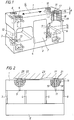
- FIG. 1 A preferred embodiment of the invention is shown in the Figures which show a complete load cell comprising a load cell housing and a built-in load transducer.
- the load cell housing consists of two substantially parallelepipedic yokes 1 and 2 interconnected by the membranes 3, 4, 5 and 6. Behind the cover plate 7 and parallel to the membranes a force transducer (not shown) is mounted and applied in such a way that only the force in the longitudinal direction of the yokes is measured.
- the longitudinal direction of the yokes is indicated by the arrow B in Figure 1.
- both yokes are provided at their end plates with two screw holes 8 to 15 for attachment against a force-introducing device (not shown) in the form of a bearing housing and a base, respectively.
- annular, outwardly-facing plane surfaces 17 of the circular tubular bodies shown in the example, which are cut out by the circular gaps 16, extend somewhat outside the remaining outer plane surfaces of the yokes.
- the contact surface of the two yokes with the bearing housing and the base, respectively, will therefore consist of four plane surfaces 17 arranged annularly around the screw holes.
- each tubular body consists of a separate body, which is provided with threads both internally and, at least to a certain extent, externally. Holes are therefore provided in the yokes which are provided with threads corresponding to the external threads of the tubular bodies. To obtain the desired gap 17, that portion of the hole in the yoke which is nearest to the outer plane surfaces of the yokes is made with a correspondingly larger diameter.
- the outer periphery of a cross section of the tubular body may, besides being formed circular as mentioned above, be formed in a plurality of different ways which as far as possible satisfy the requirements for symmetrical counter-supports.
- the periphery of the cross section of the body may, for example, be formed as a polygon, a curve different from a circle, or as parts of a circle or other curve and one or more chords. The latter will be the case if the centre of the screw holes is located so close to the longitudinal sides and the end plates of the yokes that the radius of the tubular body is larger than the distance between the centre of the screw hole and the longitudinal sides and the end plates, respectively.
- the yokes can also be made more adaptable to a possible level difference or irregularity of the base and the bearing housing, respectively, close to the contact surfaces of the screw pairs by providing the tubular bodies with one or more waists.
- the waists are formed, as will be clear from the example shown in Figure 1 and 2, by providing, on both longitudinal sides, at a distance from the outer plane surfaces of the yokes and symmetrically in relation to the centre line of the screw hole, for each screw hole two straight inwardly-directed cylindrical recesses 18 and 19 which may preferably be of circular cross section.
- the recesses are so dimensioned that those generatrices of the recesses which are located furthest away from the centre line of the screw hole at least touch the outer periphery of the holes which surround the tubular bodies.
- Figure 2 shows how the waists allow an adaptation of the end surfaces 17 and 20 of the tubular bodies 21 and 22 to a bearing housing 23 with an uneven surface facing the yoke 1.
- the uneveness of surface has been enlarged for the sake of clarity.
- each one of the bodies may be provided with only one waist.
- the waists may also be made as holes extending from the end plates of the yokes towards the bodies.
Landscapes
- Physics & Mathematics (AREA)
- General Physics & Mathematics (AREA)
- Chemical & Material Sciences (AREA)
- Analytical Chemistry (AREA)
- Health & Medical Sciences (AREA)
- Life Sciences & Earth Sciences (AREA)
- Biochemistry (AREA)
- General Health & Medical Sciences (AREA)
- Immunology (AREA)
- Pathology (AREA)
- Force Measurement Appropriate To Specific Purposes (AREA)
- Prostheses (AREA)
Abstract
Description
- The invention relates to a load cell housing according to the precharacterising part of claim 1.
- Within, inter alia, the paper, plastics, textile and metal industries, the tensile force and/or the tensile stress in the continuous material web or strip are often measured to indicate, monitor or control the manufacturing process. The measurement is normally performed in such a way that the continuous web is allowed to pass through a deflector roll. Between the bearing of the deflector roll and the base there are arranged load cells each comprising a load cell housing with a built-in transducer of preferably magnetoelastic type. The invention relates to a special design of the housing to avoid internal bending moments and stresses in the housing because of the attachment to both the base and the bearing of the deflector roll.
- To understand the importance of a good constructive design of the load cell housing, a short description of the measurement of tensile force and/or tensile stress in a moving continuous web will first be given. The deflector roll is journalled in a conventional manner in a bearing housing. Between the bearing housing and the base, the latter being formed by some kind of foundation, the load cell housing is placed. This substantially consists of two relatively stiff parallelepipedic yokes, one of which makes contact with the bearing housing and the other makes contact with the base. The yokes are connected together by a number of membranes and a transducer in such a way as to make possible a certain movability in the longitudinal direction of the yokes. The transducers are oriented such that only the force Fr in the direction of movement, that is, normally in a horizontal direction, is measured. With knowledge of the angle of entry and the angle of departure of the continuous web at the deflector roll in relation to the direction of movement mentioned, the tensile force Fd in the continuous web can be calculated in a simple manner. With knowledge of the cross section area of the continuous web in question, also the tensile stress in the web can thus be determined.
- The insertion of a transducer parallel to the above mentioned membranes between the two yokes can normally be performed in such a way that no measurable forces arise in a direction parallel to the two yokes. Nor are there any major problems from the manufacturing point of view in making the outer plane sides of the two yokes plane-parallel.
- An additional condition for obtaining a good accuracy is that the side of the bearing housing which faces the yoke of the load cell housing has a plane surface. The same demands are also placed on that surface of the base which faces the other yoke of the load cell housing. To be able to meet the given accuracy data, specified planeness requirements are often indicated.
- It is also very important always to mount the load cell at an angle of exactly 90° with the deflector roll to prevent any lateral forces from getting into the direction of measurement.
- The attachment of the load cell housing to the bearing housing and to the base, respectively, is often carried out using screws which from the side of the bearing housing and the base, respectively, are screwed into threaded holes in the yokes. Although normally specified tightening moments are prescribed for the screwing, it has proved that the attachment of the load cell housing often influences the accuracy of measurement in a very negative way because internal bending moments and forces of no inconsiderable magnitude may then arise in the load cell housing. This manifests itself in such a way that a load cell senses a tensile force in a direction parallel to the yokes without there being any continuous web on the deflector roll. Various designs of the yokes have been presented in order to reduce the above-mentioned problem. Instead of allowing the outer plane-parallel surfaces of the yokes to make close contact with the bearing housing and the base, respectively, it is possible to provide the plane surfaces of the yokes with narrow grooves parallel to the shaft of the deflector roll and placed on respective sides of the threaded holes. Such grooves are shown, inter alia, in figures in the ABB pamphlet Pillow-Block tensiometer, A07-7505 E. Otherwise, this pamphlet shows the construction of a complete load cell and how this is integrated into a production plant for continuous web where the tensile force or the tensile stress in the web need to be measured. The transducer used in this case consists of a magnetoelastic transducer which, by a suitable location of holes for an excitation and measuring winding, only measures the force in the longitudinal direction of the yokes.
- Although the introduction of the above-mentioned grooves has entailed improvements in relation to the plane-parallel outer yoke sides, the problems have not disappeared entirely. The basic reason for these problems arising is, as mentioned above, that the tightening of the screws gives rise to internal bending moments and stresses in the yokes which may result in the load cell sensing a tensile force in a direction parallel to the yokes without there being any continuous web on the deflector roll. The technical explanation of the occurence of bending moments in the yokes is that the contact surface around each screw hole in the present designs does not provide a symmetrical counter-support. By symmetrical counter-support is meant here that if the contact surface around each screw hole is conceived to consist of a large number of surface elements, then the sum of the "surface moments" of the surface elements, that is, the respective surface element area multiplied by its surface pressure and the distance to the screw centre, should be zero. Since neither the design solution with plane-parallel outer yoke sides, nor outer yoke sides with grooves exhibits a symmetrical counter-support, there will always be internal bending moments and associated mechanical stresses in the yokes.
- The invention aims at developing a load cell housing with means for connection of the load cell housing to the surface of a force-introducing device and a force-absorbing base, respectively, which connection means do not give rise to internal bending moments and associated mechanical stresses in the yokes of the load cell housing.
- To achieve this aim the invention suggests a load cell housing according to the introductory part of claim 1, which is characterized by the features of the characterizing part of claim 1.
- Further developments of the invention are characterized by the features of the additional claims.
- The invention constitutes a constructive design of the area around the screw holes of the yokes which practically allows symmetrical counter-supports for all screw connections between the yokes and the bearing housing and the abase, respectively. This means that the influence on the measurement of tensile force and tensile stress in the continuous web exerted by the attachment of the yokes, that is, internal bending moments and mechanical stresses in the yokes, is practically eliminated.
- The screw holes may either be threaded along the whole length or be threaded from the outer plane surfaces of the yokes only to such an extent into the yokes as is needed to ensure, with a certain margin, sufficient prestress in the screws. From the outer, outwardly-facing plane of the yokes there is provided, at each screw hole, a gap with a depth into the yoke which is sufficient to reduce the effect of stresses arising from the mounting of the load cell to a level permissible for each particular case. Normally, this means that the depth is larger than one-fourth of the screw hole diameter. The outwardly-facing plane surface of one tubular body thus formed around the screw holes lies somewhat outside the otherwise outer plane surfaces of the yokes. The cross section area of the body, for example as regards the outer periphery towards the gap, may be in the form of a polygon or be circular. The yokes are normally provided with four screw holes which are placed, in pairs, parallel to and near the end plates of the yokes. This means that the two yokes of the load cell housing will have, as contact surface with the bearing housing and the base, respectively, four plane surfaces centered around the screw holes. Because the tubular bodies, which now form coupling elements between the yokes and the bearing housing and the base, respectively, may be compressed axially and expand outwards during the mounting, counting from the centre line of the screw hole, practically independently of the adjacent parts of the yokes, only a minimum deformation caused by internal moments and mechanical stresses will arise in the yokes.
- The external dimensions of the tubular bodies must be chosen in such a way that the stresses from the contact pressure between the plane surfaces and the bearing housing and the base, respectively, is well within the allowable limits.
- Generally, however, it is desirable to minimize the contact surface of the load cell housing with the surroundings. This reduces the risk of foreign particles or irregularities of the base giving rise to internal bending moments or mechanical stresses in the yokes. A similar idea was behind the introduction of the grooves, described above under "Background art, The problem". However, this did not afford the advantage of the symmetrical counter-supports, provided by the tubes.
- From the point of view of lateral load, it is desirable for the two screw attachments, which are located at the end plates of the yokes, to be located as far out towards the longitudinal sides of the yokes as possible. Since, of course, equilibrium of moments must prevail between the force-absorbing contact surfaces of the yokes and the lateral load, the load on the coupling elements will be lower as the distance increases. In the design using grooves, however, there is a contact surface between the screws which is of no use.
- To render the yokes still more adaptable to, inter alia, a possible level difference or irregularity of the base and the bearing housing, respectively, at the contact surfaces of the screw pairs, the tubular bodies may be provided with one or more waists, thus reducing the flexural rigidity of the bodies. This will be clarified in the description of the different embodiments. By the waists the bending moment, which arises in the bodies in the case of an uneven base, will be reduced. An advantage of the reduced bending moment is that the effect on the yokes in the form of internal stresses and moments in the yokes will be reduced. The waists may be produced in different ways by reducing the material in the tube wall.
- By way of example, the invention will now be described in greater detail with reference to the accompanying drawings showing in
- Figure 1
- a load cell according to one embodiment of the invention,
- Figure 2
- how the waists facilitate the adaption of the tubular bodies to an uneven base.
- A preferred embodiment of the invention is shown in the Figures which show a complete load cell comprising a load cell housing and a built-in load transducer. The load cell housing consists of two substantially
parallelepipedic yokes 1 and 2 interconnected by themembranes screw holes 8 to 15 for attachment against a force-introducing device (not shown) in the form of a bearing housing and a base, respectively. All the screw holes and the surrounding part of the yokes are formed in the same way as illustrated by the sectional view at thescrew hole 11. As will be clear, viewed from the plane outer surfaces of the yokes, the screw holes are threaded along distance A. Each screw hole is surrounded by agap 16. In a preferred embodiment according to the example shown in Figure 1, the gaps are formed circularly concentrically with the threaded holes with a depth somewhat larger than that of the threaded depth. In order not to overload Figure 1 with too many reference numerals, reference is only made in Figure 1 to thegap 16 around thescrew hole 11. As will also be clear, the annular, outwardly-facing plane surfaces 17 of the circular tubular bodies shown in the example, which are cut out by thecircular gaps 16, extend somewhat outside the remaining outer plane surfaces of the yokes. The contact surface of the two yokes with the bearing housing and the base, respectively, will therefore consist of fourplane surfaces 17 arranged annularly around the screw holes. - In an alternative embodiment of the invention, each tubular body consists of a separate body, which is provided with threads both internally and, at least to a certain extent, externally. Holes are therefore provided in the yokes which are provided with threads corresponding to the external threads of the tubular bodies. To obtain the desired
gap 17, that portion of the hole in the yoke which is nearest to the outer plane surfaces of the yokes is made with a correspondingly larger diameter. - Within the scope of the invention, the outer periphery of a cross section of the tubular body may, besides being formed circular as mentioned above, be formed in a plurality of different ways which as far as possible satisfy the requirements for symmetrical counter-supports. The periphery of the cross section of the body may, for example, be formed as a polygon, a curve different from a circle, or as parts of a circle or other curve and one or more chords. The latter will be the case if the centre of the screw holes is located so close to the longitudinal sides and the end plates of the yokes that the radius of the tubular body is larger than the distance between the centre of the screw hole and the longitudinal sides and the end plates, respectively.
- As described above, the yokes can also be made more adaptable to a possible level difference or irregularity of the base and the bearing housing, respectively, close to the contact surfaces of the screw pairs by providing the tubular bodies with one or more waists. In a preferred embodiment, the waists are formed, as will be clear from the example shown in Figure 1 and 2, by providing, on both longitudinal sides, at a distance from the outer plane surfaces of the yokes and symmetrically in relation to the centre line of the screw hole, for each screw hole two straight inwardly-directed
cylindrical recesses - Figure 2 shows how the waists allow an adaptation of the end surfaces 17 and 20 of the
tubular bodies housing 23 with an uneven surface facing the yoke 1. The uneveness of surface has been enlarged for the sake of clarity. - The scope of the invention allows for several alternative embodiments and locations of the waists. As already indicated, each one of the bodies may be provided with only one waist. The waists may also be made as holes extending from the end plates of the yokes towards the bodies. Although it is advantageous, from the point of view of manufacturing, with a circular cylindrical embodiment of the waists, also other embodiments may be used.
Claims (4)
- Load cell housing with a built-in force transducer together forming a load cell with two parallelepipedic yokes (1, 2), one of which facing a force-introducing device and the other a force-absorbing base, the force transducer together with membranes (3,4,5,6) being arranged between the yokes to connect the yokes together, the force transducer being adapted to measure only the force applied to the load cell in the longitudinal direction of the yokes, and with screw holes (8 to 15) being arranged at the end plates of the yokes to attach the yokes to the force-introducing device and the base, respectively, characterized in that a gap (16) is provided around each screw hole so that a tubular body (20, 21) is formed around the screw holes and that the plane, outwardly-facing surfaces (17) of the tubular bodies are plane-parallel and extend outside the otherwise plane outwardly-facing surfaces of the yokes.
- Load cell housing according to claim 1, characterized in that the gaps (16) are arranged so that the cross section of the tubular bodies has the external shape of a polygon, a circle or another curve.
- Load cell housing according to claim 1, characterized in that the gaps are arranged so that the cross section of the tubular bodies has the external shape of parts of a circle or another curve and one or more chords.
- Load cell housing according to any of the preceding claims, characterized in that the tubular bodies are provided with one or more waists (18, 19).
Applications Claiming Priority (2)
| Application Number | Priority Date | Filing Date | Title |
|---|---|---|---|
| SE9100537 | 1991-02-25 | ||
| SE9100537A SE468023B (en) | 1991-02-25 | 1991-02-25 | LOAD CELL HOUSE WITH BUILT-IN POWER |
Publications (3)
| Publication Number | Publication Date |
|---|---|
| EP0501351A2 true EP0501351A2 (en) | 1992-09-02 |
| EP0501351A3 EP0501351A3 (en) | 1993-06-16 |
| EP0501351B1 EP0501351B1 (en) | 1996-09-11 |
Family
ID=20381972
Family Applications (1)
| Application Number | Title | Priority Date | Filing Date |
|---|---|---|---|
| EP92102993A Expired - Lifetime EP0501351B1 (en) | 1991-02-25 | 1992-02-22 | Load cell |
Country Status (6)
| Country | Link |
|---|---|
| US (1) | US5250762A (en) |
| EP (1) | EP0501351B1 (en) |
| JP (1) | JP3174378B2 (en) |
| CA (1) | CA2061751C (en) |
| DE (1) | DE69213506T2 (en) |
| SE (1) | SE468023B (en) |
Cited By (1)
| Publication number | Priority date | Publication date | Assignee | Title |
|---|---|---|---|---|
| EP1530035A1 (en) * | 2003-11-06 | 2005-05-11 | Mettler-Toledo GmbH | Force measuring cell with fastening decoupling by raised surfaces and short incisions |
Families Citing this family (16)
| Publication number | Priority date | Publication date | Assignee | Title |
|---|---|---|---|---|
| US5646376A (en) * | 1994-06-09 | 1997-07-08 | Intercomp Company | Aircraft weighing scale with improved base, platform and load cell mounting assembly |
| DE4427088C2 (en) * | 1994-07-30 | 1996-07-11 | Sartorius Gmbh | Upper pan scale with one-piece parallel guidance |
| US5604336A (en) * | 1995-03-08 | 1997-02-18 | Weigh-Tronix, Inc. | Load cell with composite end beams having portions with different elastic modulus |
| AU2002332462A1 (en) * | 2001-08-06 | 2003-02-24 | Measurement Specialties, Inc. | Weighing scale with level compensating foot assembly |
| JP2003065834A (en) * | 2001-08-29 | 2003-03-05 | Shimadzu Corp | Electronic balance |
| US7151232B2 (en) | 2002-08-06 | 2006-12-19 | Measurement Ltd. | Weighing scale with level compensating foot assembly |
| JP3670648B2 (en) * | 2003-02-07 | 2005-07-13 | 新光電子株式会社 | Load measuring mechanism |
| JP4152403B2 (en) * | 2005-06-30 | 2008-09-17 | 本田技研工業株式会社 | Seat weight sensor |
| PL2153185T3 (en) * | 2007-06-01 | 2017-09-29 | Mettler-Toledo Gmbh | Adjustable parallel guide for compact gravimetric measuring instruments |
| KR100972117B1 (en) * | 2008-05-09 | 2010-07-23 | (주)인벤티오 | Elastic body for load measurement and non-contact load measuring device using the same |
| DE102010003504A1 (en) | 2010-03-31 | 2011-10-06 | Voith Patent Gmbh | A web or strip gauge, use of such a web or strip gauge and method of determining web tension |
| EP2434265B1 (en) * | 2010-09-22 | 2014-03-05 | Wipotec Wiege- und Positioniersysteme GmbH | Weighing device with thermal decoupling |
| US9400207B2 (en) * | 2013-03-15 | 2016-07-26 | Illinois Tool Works Inc. | Sensor mounting bracket |
| US9709436B2 (en) * | 2013-03-15 | 2017-07-18 | Illinois Tool Works Inc. | Load cell that is symmetrical about a central vertical axis |
| US9494459B2 (en) * | 2014-11-30 | 2016-11-15 | Portal 724, LLC | Self-leveling scale |
| DE102017129486A1 (en) * | 2017-12-11 | 2019-06-13 | Otto Bock Healthcare Products Gmbh | Linear force measuring device and hydraulic actuator |
Family Cites Families (13)
| Publication number | Priority date | Publication date | Assignee | Title |
|---|---|---|---|---|
| US3495453A (en) * | 1967-03-16 | 1970-02-17 | Asea Ab | Pillow block tensiometer |
| SE391032B (en) * | 1974-12-03 | 1977-01-31 | Asea Ab | TRANSFORMATIVE POWER SENSOR |
| DE2510913A1 (en) * | 1975-03-13 | 1976-09-30 | Maschf Augsburg Nuernberg Ag | STORAGE OF ROLLERS IN ROTARY PRINTING MACHINES USED FOR PAPER TRAIN TENSION MEASUREMENT |
| GB2101753B (en) * | 1981-07-13 | 1985-08-07 | Defiant Weighing Limited | Load cell. |
| US4554987A (en) * | 1983-08-29 | 1985-11-26 | Dillon Benny N | Self-aligning scale assembly and method |
| US4549701A (en) * | 1983-12-16 | 1985-10-29 | Beloit Corporation | Web tension load cell |
| DE3562110D1 (en) * | 1984-05-18 | 1988-05-11 | Pietzsch Ludwig Gmbh & Co | Wheel load measuring device |
| EP0195875B1 (en) * | 1985-03-25 | 1989-02-01 | K-TRON Patent AG | Mass-and-force measuring device |
| US4653599A (en) * | 1985-06-07 | 1987-03-31 | Johnson Michael K | Load cells with overload protection and moment adjustment means |
| US4606421A (en) * | 1985-08-09 | 1986-08-19 | Hobart Corporation | Shift-error adjustment for load cell support |
| US4775018A (en) * | 1987-02-03 | 1988-10-04 | Kroll William P | Load cell assembly |
| US4765423A (en) * | 1987-11-05 | 1988-08-23 | Karpa Michael J | Load cell adaptor |
| US4804053B1 (en) * | 1987-11-10 | 1996-09-03 | Flintab Ab | Rocker pin load cell |
-
1991
- 1991-02-25 SE SE9100537A patent/SE468023B/en not_active IP Right Cessation
-
1992
- 1992-01-07 US US07/817,492 patent/US5250762A/en not_active Expired - Lifetime
- 1992-02-22 DE DE69213506T patent/DE69213506T2/en not_active Expired - Fee Related
- 1992-02-22 EP EP92102993A patent/EP0501351B1/en not_active Expired - Lifetime
- 1992-02-24 CA CA002061751A patent/CA2061751C/en not_active Expired - Fee Related
- 1992-02-24 JP JP03649792A patent/JP3174378B2/en not_active Expired - Fee Related
Cited By (3)
| Publication number | Priority date | Publication date | Assignee | Title |
|---|---|---|---|---|
| EP1530035A1 (en) * | 2003-11-06 | 2005-05-11 | Mettler-Toledo GmbH | Force measuring cell with fastening decoupling by raised surfaces and short incisions |
| US7220924B2 (en) | 2003-11-06 | 2007-05-22 | Mettler-Toledo Ag | Fastening arrangement of a force-transmitting device |
| US7365276B2 (en) | 2003-11-06 | 2008-04-29 | Mettler-Toledo Ag | Force-transmitting device |
Also Published As
| Publication number | Publication date |
|---|---|
| SE468023B (en) | 1992-10-19 |
| EP0501351A3 (en) | 1993-06-16 |
| DE69213506D1 (en) | 1996-10-17 |
| JPH04324332A (en) | 1992-11-13 |
| SE9100537D0 (en) | 1991-02-25 |
| DE69213506T2 (en) | 1997-04-24 |
| JP3174378B2 (en) | 2001-06-11 |
| CA2061751A1 (en) | 1992-08-26 |
| SE9100537L (en) | 1992-08-26 |
| EP0501351B1 (en) | 1996-09-11 |
| CA2061751C (en) | 1997-06-03 |
| US5250762A (en) | 1993-10-05 |
Similar Documents
| Publication | Publication Date | Title |
|---|---|---|
| EP0501351B1 (en) | Load cell | |
| US6122978A (en) | Web tension cantilever transducer apparatus | |
| US5756943A (en) | Load cell | |
| CA1307408C (en) | Web tension transducer | |
| US6898989B2 (en) | Load cell | |
| CN210322103U (en) | Small-torque flange type torque sensor | |
| US4811610A (en) | Weighing cell | |
| CN210426836U (en) | Novel strain type cylindrical force transducer | |
| EP0814328B1 (en) | A device for measuring compressive forces | |
| US4520679A (en) | Load converter | |
| US5537878A (en) | Strip flatness measuring device | |
| EP1528382B1 (en) | Combination of bearing housing and load measuring plate | |
| JP3128065U7 (en) | ||
| CN120445323A (en) | A force and acceleration composite sensor and adjustment method | |
| CN219178787U (en) | Three-dimensional force sensor of wide range | |
| GB2052078A (en) | Load Cell | |
| DE19640717A1 (en) | Torque moment measuring hub | |
| JPH07507386A (en) | Exchanger beam and beam assembly | |
| WO2017130448A1 (en) | Load detector | |
| CN207923333U (en) | A kind of Cantilevered tension force sensor | |
| CN222912862U (en) | A new type of twist ring sensor and combined module | |
| JPH0510836A (en) | Tension detector | |
| CN219161516U (en) | High-precision six-dimensional force sensor | |
| CN216899154U (en) | Connection structure of strain type weighing sensor | |
| US3421132A (en) | Shear load cell |
Legal Events
| Date | Code | Title | Description |
|---|---|---|---|
| PUAI | Public reference made under article 153(3) epc to a published international application that has entered the european phase |
Free format text: ORIGINAL CODE: 0009012 |
|
| AK | Designated contracting states |
Kind code of ref document: A2 Designated state(s): DE FR GB IT |
|
| PUAL | Search report despatched |
Free format text: ORIGINAL CODE: 0009013 |
|
| RHK1 | Main classification (correction) |
Ipc: G01L 5/10 |
|
| AK | Designated contracting states |
Kind code of ref document: A3 Designated state(s): DE FR GB IT |
|
| 17P | Request for examination filed |
Effective date: 19930918 |
|
| 17Q | First examination report despatched |
Effective date: 19950206 |
|
| GRAH | Despatch of communication of intention to grant a patent |
Free format text: ORIGINAL CODE: EPIDOS IGRA |
|
| GRAH | Despatch of communication of intention to grant a patent |
Free format text: ORIGINAL CODE: EPIDOS IGRA |
|
| GRAA | (expected) grant |
Free format text: ORIGINAL CODE: 0009210 |
|
| AK | Designated contracting states |
Kind code of ref document: B1 Designated state(s): DE FR GB IT |
|
| REF | Corresponds to: |
Ref document number: 69213506 Country of ref document: DE Date of ref document: 19961017 |
|
| ITF | It: translation for a ep patent filed | ||
| ET | Fr: translation filed | ||
| PLBE | No opposition filed within time limit |
Free format text: ORIGINAL CODE: 0009261 |
|
| STAA | Information on the status of an ep patent application or granted ep patent |
Free format text: STATUS: NO OPPOSITION FILED WITHIN TIME LIMIT |
|
| 26N | No opposition filed | ||
| REG | Reference to a national code |
Ref country code: GB Ref legal event code: IF02 |
|
| PGFP | Annual fee paid to national office [announced via postgrant information from national office to epo] |
Ref country code: FR Payment date: 20050208 Year of fee payment: 14 |
|
| PGFP | Annual fee paid to national office [announced via postgrant information from national office to epo] |
Ref country code: GB Payment date: 20050216 Year of fee payment: 14 |
|
| PGFP | Annual fee paid to national office [announced via postgrant information from national office to epo] |
Ref country code: DE Payment date: 20050217 Year of fee payment: 14 |
|
| PG25 | Lapsed in a contracting state [announced via postgrant information from national office to epo] |
Ref country code: GB Free format text: LAPSE BECAUSE OF NON-PAYMENT OF DUE FEES Effective date: 20060222 |
|
| PGFP | Annual fee paid to national office [announced via postgrant information from national office to epo] |
Ref country code: IT Payment date: 20060228 Year of fee payment: 15 |
|
| PG25 | Lapsed in a contracting state [announced via postgrant information from national office to epo] |
Ref country code: DE Free format text: LAPSE BECAUSE OF NON-PAYMENT OF DUE FEES Effective date: 20060901 |
|
| GBPC | Gb: european patent ceased through non-payment of renewal fee |
Effective date: 20060222 |
|
| REG | Reference to a national code |
Ref country code: FR Ref legal event code: ST Effective date: 20061031 |
|
| PG25 | Lapsed in a contracting state [announced via postgrant information from national office to epo] |
Ref country code: FR Free format text: LAPSE BECAUSE OF NON-PAYMENT OF DUE FEES Effective date: 20060228 |
|
| PG25 | Lapsed in a contracting state [announced via postgrant information from national office to epo] |
Ref country code: IT Free format text: LAPSE BECAUSE OF NON-PAYMENT OF DUE FEES Effective date: 20070222 |