EP0500606B1 - Producing prostheses - Google Patents
Producing prostheses Download PDFInfo
- Publication number
- EP0500606B1 EP0500606B1 EP90916123A EP90916123A EP0500606B1 EP 0500606 B1 EP0500606 B1 EP 0500606B1 EP 90916123 A EP90916123 A EP 90916123A EP 90916123 A EP90916123 A EP 90916123A EP 0500606 B1 EP0500606 B1 EP 0500606B1
- Authority
- EP
- European Patent Office
- Prior art keywords
- blank
- article
- resist
- etching
- shape
- Prior art date
- Legal status (The legal status is an assumption and is not a legal conclusion. Google has not performed a legal analysis and makes no representation as to the accuracy of the status listed.)
- Expired - Lifetime
Links
- 238000000034 method Methods 0.000 claims abstract description 42
- 238000005530 etching Methods 0.000 claims abstract description 28
- 239000000463 material Substances 0.000 claims abstract description 28
- 238000004519 manufacturing process Methods 0.000 claims abstract description 21
- 238000005452 bending Methods 0.000 claims abstract description 13
- 230000008569 process Effects 0.000 claims abstract description 10
- 238000012545 processing Methods 0.000 claims abstract description 9
- 229910052751 metal Inorganic materials 0.000 claims description 22
- 239000002184 metal Substances 0.000 claims description 22
- 239000011248 coating agent Substances 0.000 claims description 6
- 238000000576 coating method Methods 0.000 claims description 6
- 239000003792 electrolyte Substances 0.000 claims description 6
- 239000002253 acid Substances 0.000 claims description 3
- 238000010923 batch production Methods 0.000 claims description 3
- 238000005498 polishing Methods 0.000 claims description 3
- 238000011960 computer-aided design Methods 0.000 claims description 2
- XLYOFNOQVPJJNP-UHFFFAOYSA-M hydroxide Chemical compound [OH-] XLYOFNOQVPJJNP-UHFFFAOYSA-M 0.000 claims description 2
- 239000012266 salt solution Substances 0.000 claims 1
- 208000010392 Bone Fractures Diseases 0.000 abstract description 9
- 238000001356 surgical procedure Methods 0.000 abstract description 6
- 208000014674 injury Diseases 0.000 abstract description 4
- 208000006670 Multiple fractures Diseases 0.000 abstract description 3
- 230000008733 trauma Effects 0.000 abstract description 2
- 210000000988 bone and bone Anatomy 0.000 description 14
- 238000003754 machining Methods 0.000 description 7
- 206010017076 Fracture Diseases 0.000 description 6
- 239000004033 plastic Substances 0.000 description 5
- 229920003023 plastic Polymers 0.000 description 5
- 230000001097 osteosynthetic effect Effects 0.000 description 4
- 230000008468 bone growth Effects 0.000 description 3
- 239000003153 chemical reaction reagent Substances 0.000 description 3
- 150000002739 metals Chemical class 0.000 description 3
- 239000002985 plastic film Substances 0.000 description 3
- 239000002904 solvent Substances 0.000 description 3
- 239000010935 stainless steel Substances 0.000 description 3
- 229910001220 stainless steel Inorganic materials 0.000 description 3
- 206010028980 Neoplasm Diseases 0.000 description 2
- 208000027418 Wounds and injury Diseases 0.000 description 2
- 238000013459 approach Methods 0.000 description 2
- 230000008901 benefit Effects 0.000 description 2
- 230000006378 damage Effects 0.000 description 2
- 238000011161 development Methods 0.000 description 2
- 230000001815 facial effect Effects 0.000 description 2
- 238000002513 implantation Methods 0.000 description 2
- 230000001939 inductive effect Effects 0.000 description 2
- 238000012986 modification Methods 0.000 description 2
- 230000004048 modification Effects 0.000 description 2
- 230000008439 repair process Effects 0.000 description 2
- 239000000126 substance Substances 0.000 description 2
- RTAQQCXQSZGOHL-UHFFFAOYSA-N Titanium Chemical compound [Ti] RTAQQCXQSZGOHL-UHFFFAOYSA-N 0.000 description 1
- 239000002313 adhesive film Substances 0.000 description 1
- 229910045601 alloy Inorganic materials 0.000 description 1
- 239000000956 alloy Substances 0.000 description 1
- 238000004458 analytical method Methods 0.000 description 1
- 201000011510 cancer Diseases 0.000 description 1
- 238000007796 conventional method Methods 0.000 description 1
- 238000002316 cosmetic surgery Methods 0.000 description 1
- 230000000994 depressogenic effect Effects 0.000 description 1
- 230000000694 effects Effects 0.000 description 1
- 239000008151 electrolyte solution Substances 0.000 description 1
- 230000003628 erosive effect Effects 0.000 description 1
- 238000009501 film coating Methods 0.000 description 1
- 239000012634 fragment Substances 0.000 description 1
- 238000005286 illumination Methods 0.000 description 1
- 239000007943 implant Substances 0.000 description 1
- 238000005304 joining Methods 0.000 description 1
- 238000011068 loading method Methods 0.000 description 1
- 238000012423 maintenance Methods 0.000 description 1
- 229910021645 metal ion Inorganic materials 0.000 description 1
- 229910001000 nickel titanium Inorganic materials 0.000 description 1
- 230000001575 pathological effect Effects 0.000 description 1
- 229920006255 plastic film Polymers 0.000 description 1
- 238000009417 prefabrication Methods 0.000 description 1
- 238000002360 preparation method Methods 0.000 description 1
- 238000010791 quenching Methods 0.000 description 1
- 230000000171 quenching effect Effects 0.000 description 1
- 230000005855 radiation Effects 0.000 description 1
- 230000009467 reduction Effects 0.000 description 1
- 150000003839 salts Chemical class 0.000 description 1
- 239000007787 solid Substances 0.000 description 1
- 210000001562 sternum Anatomy 0.000 description 1
- 239000010936 titanium Substances 0.000 description 1
- 229910052719 titanium Inorganic materials 0.000 description 1
- 238000013519 translation Methods 0.000 description 1
- 238000009834 vaporization Methods 0.000 description 1
Images



Classifications
-
- A—HUMAN NECESSITIES
- A61—MEDICAL OR VETERINARY SCIENCE; HYGIENE
- A61B—DIAGNOSIS; SURGERY; IDENTIFICATION
- A61B17/00—Surgical instruments, devices or methods
- A61B17/56—Surgical instruments or methods for treatment of bones or joints; Devices specially adapted therefor
- A61B17/58—Surgical instruments or methods for treatment of bones or joints; Devices specially adapted therefor for osteosynthesis, e.g. bone plates, screws or setting implements
- A61B17/88—Osteosynthesis instruments; Methods or means for implanting or extracting internal or external fixation devices
- A61B17/8863—Apparatus for shaping or cutting osteosynthesis equipment by medical personnel
-
- A—HUMAN NECESSITIES
- A61—MEDICAL OR VETERINARY SCIENCE; HYGIENE
- A61B—DIAGNOSIS; SURGERY; IDENTIFICATION
- A61B17/00—Surgical instruments, devices or methods
- A61B17/56—Surgical instruments or methods for treatment of bones or joints; Devices specially adapted therefor
- A61B17/58—Surgical instruments or methods for treatment of bones or joints; Devices specially adapted therefor for osteosynthesis, e.g. bone plates, screws or setting implements
- A61B17/68—Internal fixation devices, including fasteners and spinal fixators, even if a part thereof projects from the skin
- A61B17/80—Cortical plates, i.e. bone plates; Instruments for holding or positioning cortical plates, or for compressing bones attached to cortical plates
-
- A—HUMAN NECESSITIES
- A61—MEDICAL OR VETERINARY SCIENCE; HYGIENE
- A61F—FILTERS IMPLANTABLE INTO BLOOD VESSELS; PROSTHESES; DEVICES PROVIDING PATENCY TO, OR PREVENTING COLLAPSING OF, TUBULAR STRUCTURES OF THE BODY, e.g. STENTS; ORTHOPAEDIC, NURSING OR CONTRACEPTIVE DEVICES; FOMENTATION; TREATMENT OR PROTECTION OF EYES OR EARS; BANDAGES, DRESSINGS OR ABSORBENT PADS; FIRST-AID KITS
- A61F2/00—Filters implantable into blood vessels; Prostheses, i.e. artificial substitutes or replacements for parts of the body; Appliances for connecting them with the body; Devices providing patency to, or preventing collapsing of, tubular structures of the body, e.g. stents
- A61F2/02—Prostheses implantable into the body
- A61F2/30—Joints
- A61F2/3094—Designing or manufacturing processes
- A61F2/30942—Designing or manufacturing processes for designing or making customized prostheses, e.g. using templates, CT or NMR scans, finite-element analysis or CAD-CAM techniques
-
- B—PERFORMING OPERATIONS; TRANSPORTING
- B29—WORKING OF PLASTICS; WORKING OF SUBSTANCES IN A PLASTIC STATE IN GENERAL
- B29C—SHAPING OR JOINING OF PLASTICS; SHAPING OF MATERIAL IN A PLASTIC STATE, NOT OTHERWISE PROVIDED FOR; AFTER-TREATMENT OF THE SHAPED PRODUCTS, e.g. REPAIRING
- B29C53/00—Shaping by bending, folding, twisting, straightening or flattening; Apparatus therefor
- B29C53/02—Bending or folding
- B29C53/04—Bending or folding of plates or sheets
- B29C53/06—Forming folding lines by pressing or scoring
- B29C53/063—Forming folding lines by pressing or scoring combined with folding
-
- A—HUMAN NECESSITIES
- A61—MEDICAL OR VETERINARY SCIENCE; HYGIENE
- A61F—FILTERS IMPLANTABLE INTO BLOOD VESSELS; PROSTHESES; DEVICES PROVIDING PATENCY TO, OR PREVENTING COLLAPSING OF, TUBULAR STRUCTURES OF THE BODY, e.g. STENTS; ORTHOPAEDIC, NURSING OR CONTRACEPTIVE DEVICES; FOMENTATION; TREATMENT OR PROTECTION OF EYES OR EARS; BANDAGES, DRESSINGS OR ABSORBENT PADS; FIRST-AID KITS
- A61F2/00—Filters implantable into blood vessels; Prostheses, i.e. artificial substitutes or replacements for parts of the body; Appliances for connecting them with the body; Devices providing patency to, or preventing collapsing of, tubular structures of the body, e.g. stents
- A61F2/02—Prostheses implantable into the body
- A61F2/30—Joints
- A61F2/3094—Designing or manufacturing processes
- A61F2/30942—Designing or manufacturing processes for designing or making customized prostheses, e.g. using templates, CT or NMR scans, finite-element analysis or CAD-CAM techniques
- A61F2002/30952—Designing or manufacturing processes for designing or making customized prostheses, e.g. using templates, CT or NMR scans, finite-element analysis or CAD-CAM techniques using CAD-CAM techniques or NC-techniques
-
- B—PERFORMING OPERATIONS; TRANSPORTING
- B29—WORKING OF PLASTICS; WORKING OF SUBSTANCES IN A PLASTIC STATE IN GENERAL
- B29C—SHAPING OR JOINING OF PLASTICS; SHAPING OF MATERIAL IN A PLASTIC STATE, NOT OTHERWISE PROVIDED FOR; AFTER-TREATMENT OF THE SHAPED PRODUCTS, e.g. REPAIRING
- B29C37/00—Component parts, details, accessories or auxiliary operations, not covered by group B29C33/00 or B29C35/00
- B29C37/0053—Moulding articles characterised by the shape of the surface, e.g. ribs, high polish
- B29C37/0057—Moulding single grooves or ribs, e.g. tear lines
Definitions
- This invention relates to the production of prostheses such as are used in orthopaedic and trauma surgery for pinning broken bones.
- such prostheses are selected by the surgeon from a set or kit of standard sizes and shapes of plate or strip having pre-drilled holes for screws. These may be capable of some limited bending and/or cropping to adapt a specific size of strip or shape to more closely suit the circumferences of any particular fracture.
- the type of pinning possible using these conventional prostheses is limited in scope because of their 2-dimensional configuration which is often unsatisfactory from both a surgical and mechanical strength point of view.
- a wider range of prosthetic shapes would facilitate different and better pinning techniques, but the prefabrication of a complete range would be a near-impossible task and the maintenance of a comprehensive inventory to cover all eventualities prohibitively expensive, to say nothing of the difficulty of selecting a shape and size from such a plethora of possibilities.
- the present invention provides methods and apparatus for the production of articles that inter alia facilitate the rapid, on-site production of medically supervised custom-made prostheses.
- the invention comprises a method for the rapid, one-off or small batch production of a shaped article such as a surgical prosthesis characterised by comprising the steps of
- the material will be 18/8 type stainless steel, but the development of other medically suitable materials such as titanium or plastics cannot be ruled out.
- the blank may be prepared with fold lines which may be made by etching or, more rapidly, by electrochemical machining (ECM).
- fold lines may also be etched such for example as apertures as for screws and pins and the required perimeter of the prosthesis.
- the acid resist layer which may comprise a wax, collodial gel or plastic or rubber adhesive film coating, may be removed mechanically as by a blade, a rotary tool or an ultrasonic tool, or by vaporisation as by an electric discharge or laser.
- the resist layer may also be removed by selectively applying a chemical reagent or solvent as by an airbrush or jet printer. Resist may also, of course, be selectively applied, rather than applied overall and then removed selectively.
- the blank may be etched concurrently on both faces, especially for the production of screw and/or pin apertures and the perimeter, but also for producing oppositely-directed curved regions. Etching of such features can leave sharp ridges or burrs, which can be removed by electropolishing. Screw and/or pin apertures or holes may also be produced by a drill or punch or other purely mechanical means where convenient.
- the blank may be processed using numerically-controlled tool means, such as a blade or rotary tool, laser or an airbrush or jet printer applying a reagent or solvent, and may be prepared, for example on an X-Y table or CAD type plotter, according to instructions derived from a programmed computer supplied with data specifying the shape of the prosthesis required.
- the computer may control the blank preparation and the CAD facility may involve the use of X-ray photographs of the prosthesis site.
- Another technique involves interposing an apertured non-conducting layer e.g. of plastic sheet between the electrode and the workpiece.
- the apertures may be made by a rotating tool, a laser, and ultrasonic cutter or in any other convenient manner.
- the invention also comprises apparatus for the production of shaped articles such as a surgical prosthesis from preformed blanks comprising blank processing means predetermining the shape of article required and processing the blank by removing material therefrom to leave an article of the predetermined shape or a processed blank from which an article of the predetermined shape may be made by bending the blank, characterised by etching (which may be electrochemical machining) means to remove material from the blank using a resist, and computer aided resist removal means.
- blank processing means predetermining the shape of article required and processing the blank by removing material therefrom to leave an article of the predetermined shape or a processed blank from which an article of the predetermined shape may be made by bending the blank, characterised by etching (which may be electrochemical machining) means to remove material from the blank using a resist, and computer aided resist removal means.
- Figures 1 to 13 illustrate the production of prostheses 11 such as are used in surgery for pinning broken bones.
- the prostheses may take various general shapes, sizes and thicknesses according to the purpose for which they are being implanted.
- Photographic techniques may of course be developed in the future which will reduce the time and cost. Meanwhile, however, etched or electrochemically machined (ECM) plates can be produced by other methods which do not suffer the disadvantages of the current photographic techniques.
- ECM electrochemically machined
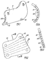
- Figure 1 illustrates a typical plate 11 which can readily be produced as herein described. It is designed to fit partially around sections of broken bone and be secured thereto by screws or pins for which matching holes 12 are provided.
- the conventional techniques for joining bones have involved connecting the bones by flat plates using angled screws which, on tightening up, draw the broken ends into tight engagement. It is now thought to be better in fact to leave the ends separated by a small gap, for example a millimetre or less, which will eventually be bridged by new bone growth. This is well-nigh impossible using the conventional flat plate or strip, but is easily achieved using a 3-dimensional prosthesis as illustrated which has a degree of mechanical strength to support the bone structure.
- the prosthesis 11 of Figure 1 is made by plastic deformation of a blank 21 comprising a flat plate as shown in Figures 2 and 3 which has been etched or electrochemically machined with fold lines 22.
- a blank 21 comprising a flat plate as shown in Figures 2 and 3 which has been etched or electrochemically machined with fold lines 22.
- fold lines 22 Using suitably-positioned such fold lines, quite complicated shapes can be produced by deforming stainless steel plates - this can be done by hand or with the aid of a simple bending jig - the fold lines determining the extent to which the metal can be bent, and thus determining the final shape of the article with a high degree of precision.
- Figure 4 shows in cross-section the blank 21 after bending on the fold lines.
- the fold lines are U-shaped grooves with angled sides and essentially the plate will fold easily along the line of the grooves until their corners come together and no further.
- the obtuse angle of the bend is determined by the width of the groove which is accurately prepared prior to etching or ECM.
- a groove width equal to the material thickness will result in a near 90° included angle bend. It is therefore practical to provide a multi-faced polygon which approximates closely to a circular or elliptical curve by the number and width of parallel or diverging grooves. It will, of course, be possible for the surgeon to make small adjustments to the final shape, depending on the precise configuration of the fold lines and the material of which the plate is made.
- Figures 5A and 5B show a sheet material plate 51 marked out on front (5A) and reverse (5B) faces for the production of the blank 21 of Figures 2 and 3.
- the plate 51 can, in a surgical situation, be selected from a range of sizes supplied as a set or kit for the purpose, once the overall dimensions of the prosthesis have been determined.
- the face (5A) is marked with perimeter lines 52 and screwhole areas or outlines 53 relative to datum holes 50 predrilled in the prepared sheet, while the reverse is also marked with perimeter lines 54 precisely underneath the perimeter lines 52 and a mirror image using the identical datum holes 50.
- Screwhole areas or outlines 55 are marked on the reverse to a smaller diameter than the areas or outlines 53 to provide a countersink feature. For angled screws, the areas or outlines 55 can be offset as compared to the areas or outlines 53.
- the reverse is also marked with the fold lines 22. If curvature were required in opposite directions, so that parts of one face were convex while other parts were concave, fold lines would, of course, be produced on both faces.
- marking is meant, of course, the removal or modification of a resist, which may be a wax coating or a rubber or plastic film adhered to the metal surface to allow the etchant or ECM electrolyte access to the metal at the marked places.
- the blank 21 looks, in cross-section, as shown in Figure 6, where the trims 61 are shown, however, as still in position. In practice, these will fall or be broken off.
- the etching or ECM process leaves sharp burrs 62 here, however, which need to be removed. This is conveniently achieved by electro-polishing, in which an electric potential is applied to the blank while in an etchant which effects rapid erosion of sharp features by comparison with flat regions, to leave the blank looking, in cross-section, as shown in Figure 7.
- Holes may be drilled or punched into the blank if the etching or ECM process is not double-sided, so as to speed up the process.
- FIGS 8 to 13 illustrate diagrammatically the sequence of operations involved in one method of producing the prosthesis 11 of Figure 1.
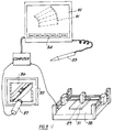
- Figure 8 illustrates a CAD/CAM arrangement in which the required prosthesis is modelled on an image 81 on a screen 82 using suitable CAD techniques which might for example involve a light, magnetic or inductive pen 83 to select features from a screen-displayed menu 84, and draw and dimension the skeletonized image 81.
- Available image-processing software can perform operations on the image 81 such as rotation, translation, stretching, reversing, scaling and so on.
- a light-box 85 is provided to illuminate an X-ray photograph 86 which can be viewed with a CCD camera 87 to produce an image on the screen 82 around which the prosthesis can be sketched using the light, magnetic or inductive pen 83.
- Software can, however, also be provided to analyse X-ray images taken from different angles to provide information from which a three-dimensional representation of the fracture site can be computed and from which, in turn, the required prosthesis shape can also be worked out according to algorithms, which might be compiled initially using an expert system, for example.
- Software can also be provided then to calculate the size of blank required and to specify the fold lines and other features required to be marked to prepare the blank for etching or ECM so that it will deform into the required shape.
- the computer can then control the operation of an X-Y plotter 88 equipped with a tool 89 for marking the plate 51 to produce the blank 21.
- the tool 89 can be a blade or a rotary tool, for example a miniature air driven router, or a laser or electric discharge device to melt or vaporize a resist, or a pen or jet printer or air brush applying a reagent or solvent.
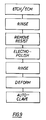
- the marked blank is then subject to the sequence of operations indicated in Figure 9, namely it is first of all etched or electrochemically machined, then rinsed, then the remaining resist is removed, following which it is re-etched or electro polished to remove sharp burrs left by the etching process, after which it is again rinsed.
- the thus prepared blank is now plastically deformed, by hand or bending tool on the fold lines, to its final shape as dictated by the fold lines, following which it is autoclaved to sterilize it ready for use.
- FIG 10 shows diagramatically a method of electrochemical machining (ECM).
- ECM electrochemical machining
- the said metal blank 93 and metal electrode 91 are connected to a source of direct current. Arcing is prevented by circulating an electrolyte 96, for example an hydroxide or ionised salt, or a conductive acid such as nitric or sulphuric, between the electrodes. Metal ions are taken into the electrolyte from the blank where the resist layer has been removed creating an etching 98 of the required dimensions.
- an electrolyte 96 for example an hydroxide or ionised salt, or a conductive acid such as nitric or sulphuric
- Figures 11 and 12 A different approach is shown in Figures 11 and 12.
- the metal blank 93 anode
- the resist coating 94 with marked etching pattern 95 is located on the solid metal electrode 91 (cathode).
- a current passes between the two electrodes as an electrolytic solution 96 flows there-between to create an etching 98 in the metal blank 93.
- Figure 12 shows a further different approach, in which a non-conducting plastic sheet 92 is interposed between the blank 93 and the electrode 91, close to the blank.
- the sheet 92 is apertured as would be a resist by routing, laser or otherwise.
- the starting blank if it does not require bending, may be nevertheless processed by metal removal techniques as discussed above, and plate stock need not then be used.
- profiled rods or tubes may be designed and produced on-site by a CAD/CAM system from cylindrical or tubular metal stock, material being removed therefrom by ECM techniques for example to produce a final osteosynthetic prosthesis.
- plastics materials for example, they may be selectively modified as by UV illumination, low power laser, ultrasonic horn or isotope radiation so as to cause shrinkage along lines on one face or the other that would bring about the required deformation.
- etching and ECM processes are especially useful in handling sheet materials which are not amenable to conventional machining or press work, for example, metals which workharden rapidly, full hardened metals used in thin springs, the glossy-amorphous alloys produced by super quenching, and the NiTi range of memory metals.
Landscapes
- Health & Medical Sciences (AREA)
- Orthopedic Medicine & Surgery (AREA)
- Life Sciences & Earth Sciences (AREA)
- Engineering & Computer Science (AREA)
- Surgery (AREA)
- Veterinary Medicine (AREA)
- Public Health (AREA)
- General Health & Medical Sciences (AREA)
- Animal Behavior & Ethology (AREA)
- Biomedical Technology (AREA)
- Heart & Thoracic Surgery (AREA)
- Molecular Biology (AREA)
- Nuclear Medicine, Radiotherapy & Molecular Imaging (AREA)
- Medical Informatics (AREA)
- Manufacturing & Machinery (AREA)
- Physics & Mathematics (AREA)
- Vascular Medicine (AREA)
- Neurology (AREA)
- Oral & Maxillofacial Surgery (AREA)
- Geometry (AREA)
- Transplantation (AREA)
- Cardiology (AREA)
- Mechanical Engineering (AREA)
- Prostheses (AREA)
- Materials For Medical Uses (AREA)
- Saccharide Compounds (AREA)
- Laminated Bodies (AREA)
- Heat Treatment Of Sheet Steel (AREA)
Abstract
Description
- This invention relates to the production of prostheses such as are used in orthopaedic and trauma surgery for pinning broken bones.
- Conventionally, such prostheses are selected by the surgeon from a set or kit of standard sizes and shapes of plate or strip having pre-drilled holes for screws. These may be capable of some limited bending and/or cropping to adapt a specific size of strip or shape to more closely suit the circumferences of any particular fracture. Generally speaking, however, the type of pinning possible using these conventional prostheses is limited in scope because of their 2-dimensional configuration which is often unsatisfactory from both a surgical and mechanical strength point of view.
- The difficulties involved in bending have led to proposals for mechanical aids to bending so-called osteosynthetic plates during surgery, such proposals being contained in DE-A-37 24 479 and DE-A-29 20 223. However, these aids do not facilitate anything like the full range of prosthetic shapes necessary and even so require still a considerable inventory of shapes and sizes of osteosynthetic plates.
- A wider range of prosthetic shapes would facilitate different and better pinning techniques, but the prefabrication of a complete range would be a near-impossible task and the maintenance of a comprehensive inventory to cover all eventualities prohibitively expensive, to say nothing of the difficulty of selecting a shape and size from such a plethora of possibilities.
- The custom-production of prostheses precisely adapted to a particular fracture has to date been substantially ruled out because of the time required to produce such prostheses by conventional production techniques and the lack, in any event, of workshop facilities close to the operating theatre.
- The present invention provides methods and apparatus for the production of articles that inter alia facilitate the rapid, on-site production of medically supervised custom-made prostheses.
- The invention comprises a method for the rapid, one-off or small batch production of a shaped article such as a surgical prosthesis characterised by comprising the steps of
- a) predetermining the 3-dimensional shape of the article required,
- b) selecting a sheet material blank from which the article may be formed,
- c) processing the blank by removing material therefrom to leave an article of the predetermined shape or a processed blank from which an article of the predetermined shape may be made by bending the blank,
- d) the material being removed using an etching (which may be an electrochemical machining) process in which resist is removed by a computer aided design/manufacturing method.
- Usually, the material will be 18/8 type stainless steel, but the development of other medically suitable materials such as titanium or plastics cannot be ruled out.
- The blank may be prepared with fold lines which may be made by etching or, more rapidly, by electrochemical machining (ECM). Features other than fold lines may also be etched such for example as apertures as for screws and pins and the required perimeter of the prosthesis.
- Although removing the resist layer could be done by the usual photographic methods, these are seen as unacceptably slow, as currently practised. So the acid resist layer, which may comprise a wax, collodial gel or plastic or rubber adhesive film coating, may be removed mechanically as by a blade, a rotary tool or an ultrasonic tool, or by vaporisation as by an electric discharge or laser. The resist layer may also be removed by selectively applying a chemical reagent or solvent as by an airbrush or jet printer. Resist may also, of course, be selectively applied, rather than applied overall and then removed selectively.
- The blank may be etched concurrently on both faces, especially for the production of screw and/or pin apertures and the perimeter, but also for producing oppositely-directed curved regions. Etching of such features can leave sharp ridges or burrs, which can be removed by electropolishing. Screw and/or pin apertures or holes may also be produced by a drill or punch or other purely mechanical means where convenient.
- The blank may be processed using numerically-controlled tool means, such as a blade or rotary tool, laser or an airbrush or jet printer applying a reagent or solvent, and may be prepared, for example on an X-Y table or CAD type plotter, according to instructions derived from a programmed computer supplied with data specifying the shape of the prosthesis required. The computer may control the blank preparation and the CAD facility may involve the use of X-ray photographs of the prosthesis site.
- Various improvements may be made on conventional ECM techniques which usually require a pre-shaped three dimensional tool to remove metal from a surface. Thus applying a resist layer to the workpiece as for normal etching techniques ensures that only the exposed metal areas are removed. Instead of applying the resist to the workpiece, however, the resist may be on the tool, and removed therefrom according to the desired pattern. The workpiece will be eroded more or less as if it had carried the resist, but there is no longer any need to remove the resist from the workpiece after the ECM operation, which cuts down the manufacturing time significantly.
- Another technique involves interposing an apertured non-conducting layer e.g. of plastic sheet between the electrode and the workpiece. The apertures may be made by a rotating tool, a laser, and ultrasonic cutter or in any other convenient manner. Here, again, there is no adhered resist layer to remove after the ECM.
- The invention also comprises apparatus for the production of shaped articles such as a surgical prosthesis from preformed blanks comprising blank processing means predetermining the shape of article required and processing the blank by removing material therefrom to leave an article of the predetermined shape or a processed blank from which an article of the predetermined shape may be made by bending the blank, characterised by etching (which may be electrochemical machining) means to remove material from the blank using a resist, and computer aided resist removal means.
- Embodiments of apparatus and methods for the production of prostheses according to the invention will now be described with reference to the accompanying drawings, in which: -
- Figure 1
- is a perspective view of a typical curved 3-dimensional shaped prosthesis,
- Figure 2
- is a developed plan view of a sheet material plate prepared for plastic deformation to the prosthesis of Figure 1,
- Figure 3
- is a section on the line III-III of Figure 2 showing etched grooves and perpendicular hole areas,
- Figure 4
- is a section like Figure 3 after deformation to the required shape,
- Figure 5A
- is one face of a blank marked from predrilled datum centres comprising a sheet metal plate prepared for etching to make the developed plate of Figures 2 and 3,
- Figure 5B
- is the reverse face of the sheet metal plate of Figure 5A marked from the same datum centres,
- Figure 6
- is a section on the line VI-VI of Figure 5A, after etching or ECM,
- Figure 7
- is the section of Figure 6, after electropolishing,
- Figure 8
- is a diagrammatic illustration of a CAD/CAM system for producing a prepared blank ready for etching or ECM,
- Figure 9
- is a diagrammatic representation of the production, by etching or by ECM using the method illustrated in Figure 10, of a prosthesis, ready for implantation, from the prepared blank,
- Figures 10, 11 and 12
- are diagrammatic illustrations of electro-chemical machining techniques,
- Figure 13
- is a diagrammatic representation of the production of a prosthesis, ready for implantation, from the prepared blank using the electro-chemical machining techniques of Figures 11 and 12.
- Figures 1 to 13 illustrate the production of
prostheses 11 such as are used in surgery for pinning broken bones. The prostheses may take various general shapes, sizes and thicknesses according to the purpose for which they are being implanted. - Besides the commonly encountered fractures of the main bones of the arms and legs where the currently available predrilled strip prostheses are generally quite satisfactory, there are many other types of bone fracture repairs that would benefit from customised 3-dimensional curved plate protheses :-
- (1) Spinal - where the many small vital vertebrae need fine and particular support
- (2) Pelvic - a common injury in motor accidents, where the complex shape of the bone and the radiating nature of the fracture paths need large plates rather than several strips to be really effective
- (3) Periarticulate - that is to say close to the main joints where several or all of the adjacent bones are broken close to their sockets, a common sporting injury for which repair often needs special plates because of the confined access
- (4) Pathological - where large parts of bones have to be surgically removed because of tumours, cancer or incorrect bone growth, requiring the bones to be bridged until new bone growth knits the separated ends together
- (5) Internal and temporary fixation - where individual specially tailored long plates are needed for instance for rejoining and pinning of the sternum after open heart surgery.
- (6) Facial - where jaw, cheek or brow bone structure is broken and depressed - a common result in motor accidents with impact on to the steering wheel or facia. Thin curved platelets to restore the original facial contours would aid cosmetic surgery.
- (7) Mutiple fractures - caused by bomb blast or bullets - need enveloping plates to support the various bone fragments, allowing them to knit correctly and ensuring true limb orientation.
- In these seven examples of major surgical areas it is often difficult or impossible to pre-determine the required implant configuration until very shortly before the prosthesis is needed - it is often not until surgery is actually in progress that the required shape can be decided upon. What the surgeon really requires is a custom-made plate produced in a very short time within the hospital itself to a shape and size specified shortly before or actually during the operation.
- The production of shaped articles from stainless steel plates by etching fold lines and other features is already known, but as currently practised does not lend itself to rapid custom production. The resists in common use are photographic and the etching pattern is produced by photographing a master drawing, usually involving a reduction of scale so that high accuracy can be achieved. It is not economical to use this process to produce articles on a one-off basis and it would in any event be difficult to complete a 15 x 5 cm component from concept to finished state in less than five hours, even if the production were to be given priority and undivided attention. Normally, two or three days at least are required if the procedure is to fit within any ordered, commercial production schedule.
- Photographic techniques may of course be developed in the future which will reduce the time and cost. Meanwhile, however, etched or electrochemically machined (ECM) plates can be produced by other methods which do not suffer the disadvantages of the current photographic techniques.
- Figure 1 illustrates a
typical plate 11 which can readily be produced as herein described. It is designed to fit partially around sections of broken bone and be secured thereto by screws or pins for which matching holes 12 are provided. - The conventional techniques for joining bones have involved connecting the bones by flat plates using angled screws which, on tightening up, draw the broken ends into tight engagement. It is now thought to be better in fact to leave the ends separated by a small gap, for example a millimetre or less, which will eventually be bridged by new bone growth. This is well-nigh impossible using the conventional flat plate or strip, but is easily achieved using a 3-dimensional prosthesis as illustrated which has a degree of mechanical strength to support the bone structure.
- The
prosthesis 11 of Figure 1 is made by plastic deformation of a blank 21 comprising a flat plate as shown in Figures 2 and 3 which has been etched or electrochemically machined with fold lines 22. Using suitably-positioned such fold lines, quite complicated shapes can be produced by deforming stainless steel plates - this can be done by hand or with the aid of a simple bending jig - the fold lines determining the extent to which the metal can be bent, and thus determining the final shape of the article with a high degree of precision. - Figure 4 shows in cross-section the blank 21 after bending on the fold lines. As will be seen from the cross-section of Figure 3, the fold lines are U-shaped grooves with angled sides and essentially the plate will fold easily along the line of the grooves until their corners come together and no further. The obtuse angle of the bend is determined by the width of the groove which is accurately prepared prior to etching or ECM. For example, a groove width equal to the material thickness will result in a near 90° included angle bend. It is therefore practical to provide a multi-faced polygon which approximates closely to a circular or elliptical curve by the number and width of parallel or diverging grooves. It will, of course, be possible for the surgeon to make small adjustments to the final shape, depending on the precise configuration of the fold lines and the material of which the plate is made.
- Figures 5A and 5B show a
sheet material plate 51 marked out on front (5A) and reverse (5B) faces for the production of the blank 21 of Figures 2 and 3. Theplate 51 can, in a surgical situation, be selected from a range of sizes supplied as a set or kit for the purpose, once the overall dimensions of the prosthesis have been determined. - The face (5A) is marked with
perimeter lines 52 and screwhole areas or outlines 53 relative to datumholes 50 predrilled in the prepared sheet, while the reverse is also marked withperimeter lines 54 precisely underneath the perimeter lines 52 and a mirror image using the identical datum holes 50. Screwhole areas or outlines 55 are marked on the reverse to a smaller diameter than the areas or outlines 53 to provide a countersink feature. For angled screws, the areas or outlines 55 can be offset as compared to the areas or outlines 53. The reverse is also marked with the fold lines 22. If curvature were required in opposite directions, so that parts of one face were convex while other parts were concave, fold lines would, of course, be produced on both faces. - By "marking" is meant, of course, the removal or modification of a resist, which may be a wax coating or a rubber or plastic film adhered to the metal surface to allow the etchant or ECM electrolyte access to the metal at the marked places.
- After etching or ECM, the blank 21 looks, in cross-section, as shown in Figure 6, where the
trims 61 are shown, however, as still in position. In practice, these will fall or be broken off. The etching or ECM process leavessharp burrs 62 here, however, which need to be removed. This is conveniently achieved by electro-polishing, in which an electric potential is applied to the blank while in an etchant which effects rapid erosion of sharp features by comparison with flat regions, to leave the blank looking, in cross-section, as shown in Figure 7. - Holes may be drilled or punched into the blank if the etching or ECM process is not double-sided, so as to speed up the process.
- Figures 8 to 13 illustrate diagrammatically the sequence of operations involved in one method of producing the
prosthesis 11 of Figure 1. - Figure 8 illustrates a CAD/CAM arrangement in which the required prosthesis is modelled on an
image 81 on ascreen 82 using suitable CAD techniques which might for example involve a light, magnetic orinductive pen 83 to select features from a screen-displayedmenu 84, and draw and dimension theskeletonized image 81. Available image-processing software can perform operations on theimage 81 such as rotation, translation, stretching, reversing, scaling and so on. A light-box 85 is provided to illuminate anX-ray photograph 86 which can be viewed with aCCD camera 87 to produce an image on thescreen 82 around which the prosthesis can be sketched using the light, magnetic orinductive pen 83. Software can, however, also be provided to analyse X-ray images taken from different angles to provide information from which a three-dimensional representation of the fracture site can be computed and from which, in turn, the required prosthesis shape can also be worked out according to algorithms, which might be compiled initially using an expert system, for example. - Software can also be provided then to calculate the size of blank required and to specify the fold lines and other features required to be marked to prepare the blank for etching or ECM so that it will deform into the required shape.
- The computer can then control the operation of an
X-Y plotter 88 equipped with atool 89 for marking theplate 51 to produce the blank 21. - The
tool 89 can be a blade or a rotary tool, for example a miniature air driven router, or a laser or electric discharge device to melt or vaporize a resist, or a pen or jet printer or air brush applying a reagent or solvent. - The marked blank is then subject to the sequence of operations indicated in Figure 9, namely it is first of all etched or electrochemically machined, then rinsed, then the remaining resist is removed, following which it is re-etched or electro polished to remove sharp burrs left by the etching process, after which it is again rinsed. The thus prepared blank is now plastically deformed, by hand or bending tool on the fold lines, to its final shape as dictated by the fold lines, following which it is autoclaved to sterilize it ready for use.
- Figure 10 shows diagramatically a method of electrochemical machining (ECM). A flat metal electrode 91 (cathode) is aligned opposite the metal blank 93 (anode) which has the resist
coating 94 with sections removed as at 95. - The said
metal blank 93 andmetal electrode 91 are connected to a source of direct current. Arcing is prevented by circulating anelectrolyte 96, for example an hydroxide or ionised salt, or a conductive acid such as nitric or sulphuric, between the electrodes. Metal ions are taken into the electrolyte from the blank where the resist layer has been removed creating anetching 98 of the required dimensions. - Thereafter the
metal blank 93 is rinsed and the remaining resistcoating 94 is removed before electropolishing and the other steps shown in Figure 9 to achieve a complete prosthesis. - A different approach is shown in Figures 11 and 12. In Figure 11 the metal blank 93 (anode) has no resist coating whatsoever. In fact the resist
coating 94 with markedetching pattern 95 is located on the solid metal electrode 91 (cathode). As described with reference to Figure 10, a current passes between the two electrodes as anelectrolytic solution 96 flows there-between to create anetching 98 in themetal blank 93. - Figure 12 shows a further different approach, in which a
non-conducting plastic sheet 92 is interposed between the blank 93 and theelectrode 91, close to the blank. Thesheet 92 is apertured as would be a resist by routing, laser or otherwise. - It may not always be necessary to circulate the electrolyte using this technique.
- An advantage of the improved methods described with reference to Figures 11 and 12, which is made clear in Figure 13, is further time saving, since the metal blank is not coated in resist, therefore the time-consuming step of resist removal after etching is avoided.
- Whilst it has been suggested in the literature - see DE-OS-2 920 223 - that point or spot loadings of an osteosynthetic plate against a bone should be avoided in favour of contact along the maximum possible surface area, it is now thought that when surrounding or partially surrounding a bone with a prosthesis as is proposed herein it is desirable not to contact the bone over large surface areas, rather by line contact as will follow from the polygonal cross-section of the prostheses naturally produced by the methods herein described so as not to completely occlude the bone.
- Although numerous alternative procedures have been described within the context of the invention it is clear that yet further variations and modifications could be adopted which would remain within the overall concept.
- The starting blank, if it does not require bending, may be nevertheless processed by metal removal techniques as discussed above, and plate stock need not then be used. For example, profiled rods or tubes may be designed and produced on-site by a CAD/CAM system from cylindrical or tubular metal stock, material being removed therefrom by ECM techniques for example to produce a final osteosynthetic prosthesis.
- If other materials are used, plastics materials for example, they may be selectively modified as by UV illumination, low power laser, ultrasonic horn or isotope radiation so as to cause shrinkage along lines on one face or the other that would bring about the required deformation.
- And although the invention has been described with particular reference to surgical prostheses, it is clearly capable of producing shaped articles for other purposes where rapid, one-off or small batch production is called for, for example, in prototype development. The etching and ECM processes are especially useful in handling sheet materials which are not amenable to conventional machining or press work, for example, metals which workharden rapidly, full hardened metals used in thin springs, the glossy-amorphous alloys produced by super quenching, and the NiTi range of memory metals.
Claims (15)
- A method for the rapid, one-off or small batch production of a shaped article such as a surgical prosthesis, characterised by comprising the steps ofa) predetermining the 3-dimensional shape of the article required,b) selecting a sheet material blank from which the article may be formed,c) processing the blank by removing material therefrom to leave an article of the predetermined shape or a processed blank from which an article of the predetermined shape may be made by bending the blank,d) the material being removed using an etching process in which resist is removed by a computer aided design/manufacturing method.
- A method according to claim 1, characterised in that the processed blank is plastically deformed to the required shape.
- A method according to claim 1 and 2, characterised in that the blank is prepared with fold lines.
- A method according to any one of claims 1 to 3, characterised in that the blank is prepared with apertures.
- A method according to any one of claims 1 to 4, used for making a prosthesis, characterised in that X-ray photographs of the prosthesis site are used in a CAD facility.
- Apparatus for the production of shaped articles such as surgical prosthesis from preformed blanks comprising blank processing means predetermining the shape of article required and processing the blank by removing material therefrom to leave an article of the predetermined shape or a processed blank from which an article of the predetermined shape may be made by bending the blank, characterised by etching means to remove material from the blank using a resist, and computer aided resist removal means.
- Apparatus according to claim 6, characterised in that the etching means are adapted to remove material to leave fold lines on the blank.
- Apparatus according to claim 6, characterised by comprising ECM means comprising a cathode and a bath containing an electrolyte.
- Apparatus according to any one of claims 6 to 8, characterised in that the blank is resist coated and marked for material removal.
- Apparatus according to any one of claims 6 to 8, characterised in that the cathode is resist coated and marked for removal of metal from the blank.
- Apparatus according to any one of claims 6 to 8, characterised in that an apertured non-conducting layer is interposed between anode and cathode in lieu of a resist layer on either.
- Apparatus according to any one of claims 6 to 11, characterised in that the electrolyte is an hydroxide, an ionising salt solution or an acid.
- Apparatus according to any one of claims 6 to 12, characterised by comprising a resist coating removal means for removing resist from the blank after an etching or ECM operation.
- Apparatus according to any one of claims 6 to 13, characterised by comprising electro polishing means for removing sharp edges and polishing the processed blank.
- Apparatus according to any one of claims 6 to 14, characterised by comprising numerically controlled tool means for marking a resist or non-conducting layer or for removing material from the blank by mechanical means.
Applications Claiming Priority (3)
| Application Number | Priority Date | Filing Date | Title |
|---|---|---|---|
| GB8925380 | 1989-11-09 | ||
| GB898925380A GB8925380D0 (en) | 1989-11-09 | 1989-11-09 | Producing prostheses |
| PCT/GB1990/001622 WO1991007139A1 (en) | 1989-11-09 | 1990-10-23 | Producing prostheses |
Publications (2)
| Publication Number | Publication Date |
|---|---|
| EP0500606A1 EP0500606A1 (en) | 1992-09-02 |
| EP0500606B1 true EP0500606B1 (en) | 1994-09-21 |
Family
ID=10666037
Family Applications (1)
| Application Number | Title | Priority Date | Filing Date |
|---|---|---|---|
| EP90916123A Expired - Lifetime EP0500606B1 (en) | 1989-11-09 | 1990-10-23 | Producing prostheses |
Country Status (8)
| Country | Link |
|---|---|
| US (1) | US5298115A (en) |
| EP (1) | EP0500606B1 (en) |
| JP (1) | JPH05501819A (en) |
| AT (1) | ATE111714T1 (en) |
| AU (1) | AU6618390A (en) |
| DE (1) | DE69012832T2 (en) |
| GB (1) | GB8925380D0 (en) |
| WO (1) | WO1991007139A1 (en) |
Families Citing this family (137)
| Publication number | Priority date | Publication date | Assignee | Title |
|---|---|---|---|---|
| US6107004A (en) * | 1991-09-05 | 2000-08-22 | Intra Therapeutics, Inc. | Method for making a tubular stent for use in medical applications |
| US6027863A (en) * | 1991-09-05 | 2000-02-22 | Intratherapeutics, Inc. | Method for manufacturing a tubular medical device |
| CA2380683C (en) * | 1991-10-28 | 2006-08-08 | Advanced Cardiovascular Systems, Inc. | Expandable stents and method for making same |
| US5365996A (en) * | 1992-06-10 | 1994-11-22 | Amei Technologies Inc. | Method and apparatus for making customized fixation devices |
| AU5542594A (en) * | 1993-02-16 | 1994-09-14 | W.E. Michael Mikhail | Orthopaedic reconstruction plate |
| US5454383A (en) * | 1993-07-02 | 1995-10-03 | Smith & Nephew Donjoy, Inc. | Method for prefitting an orthotic member to the body |
| GB2318058B (en) * | 1996-09-25 | 2001-03-21 | Ninian Spenceley Peckitt | Improvements relating to prosthetic implants |
| US6165195A (en) | 1997-08-13 | 2000-12-26 | Advanced Cardiovascylar Systems, Inc. | Stent and catheter assembly and method for treating bifurcations |
| US5894373A (en) * | 1997-09-24 | 1999-04-13 | Jaesent Inc. | Method for fabricating mirror systems |
| US6459927B1 (en) | 1999-07-06 | 2002-10-01 | Neutar, Llc | Customizable fixture for patient positioning |
| US6327491B1 (en) * | 1998-07-06 | 2001-12-04 | Neutar, Llc | Customized surgical fixture |
| US6599322B1 (en) * | 2001-01-25 | 2003-07-29 | Tecomet, Inc. | Method for producing undercut micro recesses in a surface, a surgical implant made thereby, and method for fixing an implant to bone |
| US6620332B2 (en) * | 2001-01-25 | 2003-09-16 | Tecomet, Inc. | Method for making a mesh-and-plate surgical implant |
| US7018418B2 (en) * | 2001-01-25 | 2006-03-28 | Tecomet, Inc. | Textured surface having undercut micro recesses in a surface |
| SG142164A1 (en) * | 2001-03-06 | 2008-05-28 | Univ Johns Hopkins | Simulation method for designing customized medical devices |
| US7201940B1 (en) | 2001-06-12 | 2007-04-10 | Advanced Cardiovascular Systems, Inc. | Method and apparatus for thermal spray processing of medical devices |
| JP4399263B2 (en) | 2001-10-19 | 2010-01-13 | ベイラー・カレツジ・オブ・メデイシン | Bone pressurizing device and system and method of contouring and use thereof |
| US8801720B2 (en) * | 2002-05-15 | 2014-08-12 | Otismed Corporation | Total joint arthroplasty system |
| DE60300277T2 (en) | 2002-11-08 | 2006-01-12 | Howmedica Osteonics Corp. | Laser generated porous surface |
| US6899729B1 (en) | 2002-12-18 | 2005-05-31 | Advanced Cardiovascular Systems, Inc. | Stent for treating vulnerable plaque |
| EP1430852A3 (en) * | 2002-12-19 | 2004-11-10 | Biogénie Projectos Ltda. | Method for computer controlled machining of customized medico-dental parts and blank for manufacturing prosthetic components |
| US7316710B1 (en) | 2002-12-30 | 2008-01-08 | Advanced Cardiovascular Systems, Inc. | Flexible stent |
| US6896697B1 (en) | 2002-12-30 | 2005-05-24 | Advanced Cardiovascular Systems, Inc. | Intravascular stent |
| US20050049595A1 (en) | 2003-09-03 | 2005-03-03 | Suh Sean S. | Track-plate carriage system |
| US7909860B2 (en) | 2003-09-03 | 2011-03-22 | Synthes Usa, Llc | Bone plate with captive clips |
| US7258697B1 (en) | 2003-12-22 | 2007-08-21 | Advanced Cardiovascular Systems, Inc. | Stent with anchors to prevent vulnerable plaque rupture during deployment |
| US20050165394A1 (en) * | 2004-01-23 | 2005-07-28 | Joseph Boyce | Bone fixation system and method |
| US20060082015A1 (en) * | 2004-09-30 | 2006-04-20 | Inion Ltd. | Surgical implant shaping instrument, surgical system and method |
| US7947207B2 (en) | 2005-04-12 | 2011-05-24 | Abbott Cardiovascular Systems Inc. | Method for retaining a vascular stent on a catheter |
| US7763198B2 (en) | 2005-04-12 | 2010-07-27 | Abbott Cardiovascular Systems Inc. | Method for retaining a vascular stent on a catheter |
| US8728387B2 (en) | 2005-12-06 | 2014-05-20 | Howmedica Osteonics Corp. | Laser-produced porous surface |
| EP1803513B1 (en) * | 2005-12-30 | 2017-03-29 | Howmedica Osteonics Corp. | Method of manufacturing implants using laser |
| CA2642615A1 (en) * | 2006-02-15 | 2007-08-30 | Otismed Corp | Arthroplasty jigs and related methods |
| US9808262B2 (en) | 2006-02-15 | 2017-11-07 | Howmedica Osteonics Corporation | Arthroplasty devices and related methods |
| US7415858B2 (en) | 2006-02-21 | 2008-08-26 | Tyco Healthcare Group Lp | Grindless surgical needle manufacture |
| US9173661B2 (en) | 2006-02-27 | 2015-11-03 | Biomet Manufacturing, Llc | Patient specific alignment guide with cutting surface and laser indicator |
| US9907659B2 (en) | 2007-04-17 | 2018-03-06 | Biomet Manufacturing, Llc | Method and apparatus for manufacturing an implant |
| US8864769B2 (en) | 2006-02-27 | 2014-10-21 | Biomet Manufacturing, Llc | Alignment guides with patient-specific anchoring elements |
| US8377066B2 (en) | 2006-02-27 | 2013-02-19 | Biomet Manufacturing Corp. | Patient-specific elbow guides and associated methods |
| US8608748B2 (en) | 2006-02-27 | 2013-12-17 | Biomet Manufacturing, Llc | Patient specific guides |
| US10278711B2 (en) | 2006-02-27 | 2019-05-07 | Biomet Manufacturing, Llc | Patient-specific femoral guide |
| US20080257363A1 (en) * | 2007-04-17 | 2008-10-23 | Biomet Manufacturing Corp. | Method And Apparatus For Manufacturing An Implant |
| US9345548B2 (en) | 2006-02-27 | 2016-05-24 | Biomet Manufacturing, Llc | Patient-specific pre-operative planning |
| US8092465B2 (en) | 2006-06-09 | 2012-01-10 | Biomet Manufacturing Corp. | Patient specific knee alignment guide and associated method |
| US8858561B2 (en) | 2006-06-09 | 2014-10-14 | Blomet Manufacturing, LLC | Patient-specific alignment guide |
| US8407067B2 (en) | 2007-04-17 | 2013-03-26 | Biomet Manufacturing Corp. | Method and apparatus for manufacturing an implant |
| US8133234B2 (en) | 2006-02-27 | 2012-03-13 | Biomet Manufacturing Corp. | Patient specific acetabular guide and method |
| US9289253B2 (en) | 2006-02-27 | 2016-03-22 | Biomet Manufacturing, Llc | Patient-specific shoulder guide |
| US9113971B2 (en) | 2006-02-27 | 2015-08-25 | Biomet Manufacturing, Llc | Femoral acetabular impingement guide |
| US20150335438A1 (en) | 2006-02-27 | 2015-11-26 | Biomet Manufacturing, Llc. | Patient-specific augments |
| US8608749B2 (en) | 2006-02-27 | 2013-12-17 | Biomet Manufacturing, Llc | Patient-specific acetabular guides and associated instruments |
| US7967868B2 (en) | 2007-04-17 | 2011-06-28 | Biomet Manufacturing Corp. | Patient-modified implant and associated method |
| US9339278B2 (en) | 2006-02-27 | 2016-05-17 | Biomet Manufacturing, Llc | Patient-specific acetabular guides and associated instruments |
| US8535387B2 (en) | 2006-02-27 | 2013-09-17 | Biomet Manufacturing, Llc | Patient-specific tools and implants |
| US8568487B2 (en) | 2006-02-27 | 2013-10-29 | Biomet Manufacturing, Llc | Patient-specific hip joint devices |
| US8603180B2 (en) | 2006-02-27 | 2013-12-10 | Biomet Manufacturing, Llc | Patient-specific acetabular alignment guides |
| US8591516B2 (en) | 2006-02-27 | 2013-11-26 | Biomet Manufacturing, Llc | Patient-specific orthopedic instruments |
| US9918740B2 (en) | 2006-02-27 | 2018-03-20 | Biomet Manufacturing, Llc | Backup surgical instrument system and method |
| US9795399B2 (en) | 2006-06-09 | 2017-10-24 | Biomet Manufacturing, Llc | Patient-specific knee alignment guide and associated method |
| US8460302B2 (en) | 2006-12-18 | 2013-06-11 | Otismed Corporation | Arthroplasty devices and related methods |
| US9364586B2 (en) | 2007-05-31 | 2016-06-14 | Abbott Cardiovascular Systems Inc. | Method and apparatus for improving delivery of an agent to a kidney |
| US9149610B2 (en) | 2007-05-31 | 2015-10-06 | Abbott Cardiovascular Systems Inc. | Method and apparatus for improving delivery of an agent to a kidney |
| US9144509B2 (en) | 2007-05-31 | 2015-09-29 | Abbott Cardiovascular Systems Inc. | Method and apparatus for delivering an agent to a kidney |
| US8216209B2 (en) | 2007-05-31 | 2012-07-10 | Abbott Cardiovascular Systems Inc. | Method and apparatus for delivering an agent to a kidney |
| US8265949B2 (en) | 2007-09-27 | 2012-09-11 | Depuy Products, Inc. | Customized patient surgical plan |
| EP2957243A1 (en) | 2007-09-30 | 2015-12-23 | DePuy Products, Inc. | Customized patient-specific orthopaedic surgical instrumentation |
| US8357111B2 (en) | 2007-09-30 | 2013-01-22 | Depuy Products, Inc. | Method and system for designing patient-specific orthopaedic surgical instruments |
| WO2009047767A1 (en) * | 2007-10-11 | 2009-04-16 | Tavor [I.T.N] Ltd. | Ligament and tendon prosthesis |
| USD642263S1 (en) | 2007-10-25 | 2011-07-26 | Otismed Corporation | Arthroplasty jig blank |
| US8460303B2 (en) * | 2007-10-25 | 2013-06-11 | Otismed Corporation | Arthroplasty systems and devices, and related methods |
| US10582934B2 (en) * | 2007-11-27 | 2020-03-10 | Howmedica Osteonics Corporation | Generating MRI images usable for the creation of 3D bone models employed to make customized arthroplasty jigs |
| US8311306B2 (en) | 2008-04-30 | 2012-11-13 | Otismed Corporation | System and method for image segmentation in generating computer models of a joint to undergo arthroplasty |
| US8617171B2 (en) | 2007-12-18 | 2013-12-31 | Otismed Corporation | Preoperatively planning an arthroplasty procedure and generating a corresponding patient specific arthroplasty resection guide |
| US8737700B2 (en) * | 2007-12-18 | 2014-05-27 | Otismed Corporation | Preoperatively planning an arthroplasty procedure and generating a corresponding patient specific arthroplasty resection guide |
| US8545509B2 (en) | 2007-12-18 | 2013-10-01 | Otismed Corporation | Arthroplasty system and related methods |
| US8160345B2 (en) | 2008-04-30 | 2012-04-17 | Otismed Corporation | System and method for image segmentation in generating computer models of a joint to undergo arthroplasty |
| US8777875B2 (en) | 2008-07-23 | 2014-07-15 | Otismed Corporation | System and method for manufacturing arthroplasty jigs having improved mating accuracy |
| US8221430B2 (en) * | 2007-12-18 | 2012-07-17 | Otismed Corporation | System and method for manufacturing arthroplasty jigs |
| US8715291B2 (en) * | 2007-12-18 | 2014-05-06 | Otismed Corporation | Arthroplasty system and related methods |
| US8480679B2 (en) | 2008-04-29 | 2013-07-09 | Otismed Corporation | Generation of a computerized bone model representative of a pre-degenerated state and useable in the design and manufacture of arthroplasty devices |
| US20090204213A1 (en) * | 2008-02-13 | 2009-08-13 | Depuy Products, Inc. | Metallic implants |
| US8734455B2 (en) * | 2008-02-29 | 2014-05-27 | Otismed Corporation | Hip resurfacing surgical guide tool |
| US8617175B2 (en) * | 2008-12-16 | 2013-12-31 | Otismed Corporation | Unicompartmental customized arthroplasty cutting jigs and methods of making the same |
| JP5302595B2 (en) * | 2008-08-06 | 2013-10-02 | 株式会社日立ハイテクノロジーズ | Inclination observation method and observation apparatus |
| US9375221B2 (en) * | 2008-12-29 | 2016-06-28 | Depuy (Ireland) | Orthopaedic cutting block having a chemically etched metal insert |
| DE102009028503B4 (en) | 2009-08-13 | 2013-11-14 | Biomet Manufacturing Corp. | Resection template for the resection of bones, method for producing such a resection template and operation set for performing knee joint surgery |
| US8632547B2 (en) | 2010-02-26 | 2014-01-21 | Biomet Sports Medicine, Llc | Patient-specific osteotomy devices and methods |
| US9066727B2 (en) | 2010-03-04 | 2015-06-30 | Materialise Nv | Patient-specific computed tomography guides |
| US9271744B2 (en) | 2010-09-29 | 2016-03-01 | Biomet Manufacturing, Llc | Patient-specific guide for partial acetabular socket replacement |
| US9968376B2 (en) | 2010-11-29 | 2018-05-15 | Biomet Manufacturing, Llc | Patient-specific orthopedic instruments |
| US9241745B2 (en) | 2011-03-07 | 2016-01-26 | Biomet Manufacturing, Llc | Patient-specific femoral version guide |
| US8715289B2 (en) | 2011-04-15 | 2014-05-06 | Biomet Manufacturing, Llc | Patient-specific numerically controlled instrument |
| US9675400B2 (en) | 2011-04-19 | 2017-06-13 | Biomet Manufacturing, Llc | Patient-specific fracture fixation instrumentation and method |
| US8668700B2 (en) | 2011-04-29 | 2014-03-11 | Biomet Manufacturing, Llc | Patient-specific convertible guides |
| US8956364B2 (en) | 2011-04-29 | 2015-02-17 | Biomet Manufacturing, Llc | Patient-specific partial knee guides and other instruments |
| US8532807B2 (en) | 2011-06-06 | 2013-09-10 | Biomet Manufacturing, Llc | Pre-operative planning and manufacturing method for orthopedic procedure |
| US9084618B2 (en) | 2011-06-13 | 2015-07-21 | Biomet Manufacturing, Llc | Drill guides for confirming alignment of patient-specific alignment guides |
| US20130001121A1 (en) | 2011-07-01 | 2013-01-03 | Biomet Manufacturing Corp. | Backup kit for a patient-specific arthroplasty kit assembly |
| US8764760B2 (en) | 2011-07-01 | 2014-07-01 | Biomet Manufacturing, Llc | Patient-specific bone-cutting guidance instruments and methods |
| US8597365B2 (en) | 2011-08-04 | 2013-12-03 | Biomet Manufacturing, Llc | Patient-specific pelvic implants for acetabular reconstruction |
| US9295497B2 (en) | 2011-08-31 | 2016-03-29 | Biomet Manufacturing, Llc | Patient-specific sacroiliac and pedicle guides |
| US9066734B2 (en) | 2011-08-31 | 2015-06-30 | Biomet Manufacturing, Llc | Patient-specific sacroiliac guides and associated methods |
| US9386993B2 (en) | 2011-09-29 | 2016-07-12 | Biomet Manufacturing, Llc | Patient-specific femoroacetabular impingement instruments and methods |
| ES2635542T3 (en) | 2011-10-27 | 2017-10-04 | Biomet Manufacturing, Llc | Glenoid guides specific to the patient |
| KR20130046336A (en) | 2011-10-27 | 2013-05-07 | 삼성전자주식회사 | Multi-view device of display apparatus and contol method thereof, and display system |
| US9301812B2 (en) | 2011-10-27 | 2016-04-05 | Biomet Manufacturing, Llc | Methods for patient-specific shoulder arthroplasty |
| US9554910B2 (en) | 2011-10-27 | 2017-01-31 | Biomet Manufacturing, Llc | Patient-specific glenoid guide and implants |
| US9451973B2 (en) | 2011-10-27 | 2016-09-27 | Biomet Manufacturing, Llc | Patient specific glenoid guide |
| US9237950B2 (en) | 2012-02-02 | 2016-01-19 | Biomet Manufacturing, Llc | Implant with patient-specific porous structure |
| US20150025548A1 (en) | 2012-03-08 | 2015-01-22 | Neutar, Llc | Patient and Procedure Customized Fixation and Targeting Devices for Stereotactic Frames |
| US9180010B2 (en) | 2012-04-06 | 2015-11-10 | Howmedica Osteonics Corp. | Surface modified unit cell lattice structures for optimized secure freeform fabrication |
| US9402637B2 (en) | 2012-10-11 | 2016-08-02 | Howmedica Osteonics Corporation | Customized arthroplasty cutting guides and surgical methods using the same |
| US9204977B2 (en) | 2012-12-11 | 2015-12-08 | Biomet Manufacturing, Llc | Patient-specific acetabular guide for anterior approach |
| US9060788B2 (en) | 2012-12-11 | 2015-06-23 | Biomet Manufacturing, Llc | Patient-specific acetabular guide for anterior approach |
| US9839438B2 (en) | 2013-03-11 | 2017-12-12 | Biomet Manufacturing, Llc | Patient-specific glenoid guide with a reusable guide holder |
| US9579107B2 (en) | 2013-03-12 | 2017-02-28 | Biomet Manufacturing, Llc | Multi-point fit for patient specific guide |
| US9826981B2 (en) | 2013-03-13 | 2017-11-28 | Biomet Manufacturing, Llc | Tangential fit of patient-specific guides |
| US9498233B2 (en) | 2013-03-13 | 2016-11-22 | Biomet Manufacturing, Llc. | Universal acetabular guide and associated hardware |
| US9517145B2 (en) | 2013-03-15 | 2016-12-13 | Biomet Manufacturing, Llc | Guide alignment system and method |
| US20150112349A1 (en) | 2013-10-21 | 2015-04-23 | Biomet Manufacturing, Llc | Ligament Guide Registration |
| US10282488B2 (en) | 2014-04-25 | 2019-05-07 | Biomet Manufacturing, Llc | HTO guide with optional guided ACL/PCL tunnels |
| US9408616B2 (en) | 2014-05-12 | 2016-08-09 | Biomet Manufacturing, Llc | Humeral cut guide |
| US9561040B2 (en) | 2014-06-03 | 2017-02-07 | Biomet Manufacturing, Llc | Patient-specific glenoid depth control |
| US9839436B2 (en) | 2014-06-03 | 2017-12-12 | Biomet Manufacturing, Llc | Patient-specific glenoid depth control |
| US9826994B2 (en) | 2014-09-29 | 2017-11-28 | Biomet Manufacturing, Llc | Adjustable glenoid pin insertion guide |
| US9833245B2 (en) | 2014-09-29 | 2017-12-05 | Biomet Sports Medicine, Llc | Tibial tubercule osteotomy |
| US9820868B2 (en) | 2015-03-30 | 2017-11-21 | Biomet Manufacturing, Llc | Method and apparatus for a pin apparatus |
| US10568647B2 (en) | 2015-06-25 | 2020-02-25 | Biomet Manufacturing, Llc | Patient-specific humeral guide designs |
| US10226262B2 (en) | 2015-06-25 | 2019-03-12 | Biomet Manufacturing, Llc | Patient-specific humeral guide designs |
| EP3195891B1 (en) * | 2016-01-25 | 2021-10-06 | Roche Diabetes Care GmbH | Medical device and process for manufacturing |
| US10130465B2 (en) | 2016-02-23 | 2018-11-20 | Abbott Cardiovascular Systems Inc. | Bifurcated tubular graft for treating tricuspid regurgitation |
| CN105832396A (en) * | 2016-04-27 | 2016-08-10 | 广州雄俊智能科技有限公司 | Personalized bone fracture plate and manufacturing method thereof |
| US10722310B2 (en) | 2017-03-13 | 2020-07-28 | Zimmer Biomet CMF and Thoracic, LLC | Virtual surgery planning system and method |
| AU2018203479B2 (en) | 2017-05-18 | 2024-04-18 | Howmedica Osteonics Corp. | High fatigue strength porous structure |
| WO2019204443A1 (en) | 2018-04-17 | 2019-10-24 | Stryker European Holdings I, Llc | On-demand implant customization in a surgical setting |
| US11051829B2 (en) | 2018-06-26 | 2021-07-06 | DePuy Synthes Products, Inc. | Customized patient-specific orthopaedic surgical instrument |
| DE102019105268A1 (en) | 2019-03-01 | 2020-09-03 | Aesculap Ag | Medical instrument and method for manufacturing a medical instrument |
Family Cites Families (11)
| Publication number | Priority date | Publication date | Assignee | Title |
|---|---|---|---|---|
| US3325319A (en) * | 1963-12-18 | 1967-06-13 | Buckbee Mears Co | Process for etching arcuately shaped metal sheets |
| US3420142A (en) * | 1966-09-15 | 1969-01-07 | Lockformer Co The | Machine for cutting formations of different shapes in fiberboard |
| US3508108A (en) * | 1967-01-16 | 1970-04-21 | Varian Associates | Comb-shaped ceramic supports for helix derived slow wave circuits |
| DE2920223A1 (en) * | 1979-05-18 | 1980-11-27 | Maschf Augsburg Nuernberg Ag | Osteo-synthesis plate shaping process - involves storage of unhardened plate for shaping and hardening after precise diagnosis of injuries |
| US4466858A (en) * | 1981-07-29 | 1984-08-21 | Lynell Medical Technology Inc. | Intraocular and extraocular lens construction and method of making the same |
| FR2574009B1 (en) * | 1984-11-30 | 1991-02-22 | Telemecanique Electrique | SYSTEM FOR ASSISTING THE CREATION AND INDUSTRIALIZATION OF OBJECTS OBTAINED BY CUTTING AND DEFORMING FROM SHEET METALS |
| SE8500034L (en) * | 1985-01-04 | 1986-07-05 | Bertil Hansson | SOCIETY FOR DIFFERENT FIELD PENDANT |
| DE3516862A1 (en) * | 1985-05-10 | 1986-11-13 | Resopal Werk H. Römmler GmbH, 6800 Mannheim | METHOD FOR PRODUCING COMPONENTS |
| DE3855423T2 (en) * | 1987-04-07 | 1997-01-23 | Richard Allison Pollock | Process for the production of anatomically preformed bone plates |
| JPS63289990A (en) * | 1987-05-22 | 1988-11-28 | Mitsubishi Electric Corp | Manufacture of printed wiring board |
| DE3724479A1 (en) * | 1987-07-24 | 1989-02-02 | Jansson Volkmar Dipl Ing Dr Me | Bending device for the individual pre-bending of osteosynthesis plates during surgery |
-
1989
- 1989-11-09 GB GB898925380A patent/GB8925380D0/en active Pending
-
1990
- 1990-10-23 WO PCT/GB1990/001622 patent/WO1991007139A1/en not_active Ceased
- 1990-10-23 US US07/856,029 patent/US5298115A/en not_active Expired - Fee Related
- 1990-10-23 AT AT90916123T patent/ATE111714T1/en not_active IP Right Cessation
- 1990-10-23 JP JP2514823A patent/JPH05501819A/en active Pending
- 1990-10-23 DE DE69012832T patent/DE69012832T2/en not_active Expired - Fee Related
- 1990-10-23 AU AU66183/90A patent/AU6618390A/en not_active Abandoned
- 1990-10-23 EP EP90916123A patent/EP0500606B1/en not_active Expired - Lifetime
Also Published As
| Publication number | Publication date |
|---|---|
| JPH05501819A (en) | 1993-04-08 |
| WO1991007139A1 (en) | 1991-05-30 |
| US5298115A (en) | 1994-03-29 |
| DE69012832T2 (en) | 1995-05-11 |
| EP0500606A1 (en) | 1992-09-02 |
| AU6618390A (en) | 1991-06-13 |
| DE69012832D1 (en) | 1994-10-27 |
| GB8925380D0 (en) | 1989-12-28 |
| ATE111714T1 (en) | 1994-10-15 |
Similar Documents
| Publication | Publication Date | Title |
|---|---|---|
| US5298115A (en) | Producing prostheses | |
| US6663765B2 (en) | Method and device for the manufacture of the medical expanding stents | |
| EP2792333B1 (en) | Cost-effective method for manufacturing metal cranial prostheses | |
| EP1229147A1 (en) | Method for producing undercut recesses in a surface, a surgical implant made thereby and a method for fixing an implant to bone | |
| EP3166537A1 (en) | Surgical kit for cartilage repair comprising implant and a set of tools | |
| WO2013055203A1 (en) | Method to provide at least one patient specific device to be used for bone correction, a treatment kit, a method of operating a data-processing system, a computer program, and a correction and fixation device and a cutting assisting device for bone correction. | |
| KR20190045923A (en) | Apparatus and method for manufacturing artificial solid bone | |
| Kumar et al. | Application of incremental sheet forming (ISF) toward biomedical and medical implants | |
| Stoodley et al. | Titanium cranioplasty using 3-D computer modelling of skull defects | |
| WO1992006654A1 (en) | Prostheses and methods and apparatus for making same | |
| JP2001001229A (en) | Working method for replica | |
| EP4514275A1 (en) | Bendable titanium-alloy implants | |
| Garriga-Majo et al. | Optimisation of the superplastic forming of a dental implant for bone augmentation using finite element simulations | |
| US20230347013A1 (en) | Bendable Titanium-Alloy Implants, And Related Systems And Methods | |
| US20210062347A1 (en) | Composition and method for creating nanoscale surface geometry on a cobalt chromium implantable device | |
| JP2014161520A (en) | Implant and manufacturing method thereof | |
| EP1229871B1 (en) | An element intended to be implanted in body tissue, and a device for manufacturing such an element | |
| Mamros et al. | Investigation using single point incremental forming (SPIF) to fabricate patient-specific, titanium orbital floor implants | |
| Chrzan et al. | Individually fitted hearing aid device manufactured using rapid prototyping based on ear CT: a case report | |
| KR20250103322A (en) | Method and system for manufacturing patient specific surgical metal plates using screw hole information based on surgical planning | |
| CN120938634A (en) | Orthodontic brackets and their manufacturing methods | |
| Bhoyar et al. | Application of single point incremental forming for biomedical implants: a review | |
| Dundas | EDM for the Long Run | |
| Yang et al. | Wire EDM for Metallic Biomaterial Rapid Manufacturing | |
| WO2006083955A2 (en) | Method for the texturing of surfaces by aqueous plasma electrolysis |
Legal Events
| Date | Code | Title | Description |
|---|---|---|---|
| PUAI | Public reference made under article 153(3) epc to a published international application that has entered the european phase |
Free format text: ORIGINAL CODE: 0009012 |
|
| 17P | Request for examination filed |
Effective date: 19920608 |
|
| AK | Designated contracting states |
Kind code of ref document: A1 Designated state(s): AT BE CH DE DK ES FR GB IT LI LU NL SE |
|
| 17Q | First examination report despatched |
Effective date: 19931213 |
|
| GRAA | (expected) grant |
Free format text: ORIGINAL CODE: 0009210 |
|
| AK | Designated contracting states |
Kind code of ref document: B1 Designated state(s): AT BE CH DE DK ES FR GB IT LI LU NL SE |
|
| PG25 | Lapsed in a contracting state [announced via postgrant information from national office to epo] |
Ref country code: AT Effective date: 19940921 Ref country code: IT Free format text: LAPSE BECAUSE OF FAILURE TO SUBMIT A TRANSLATION OF THE DESCRIPTION OR TO PAY THE FEE WITHIN THE PRESCRIBED TIME-LIMIT;WARNING: LAPSES OF ITALIAN PATENTS WITH EFFECTIVE DATE BEFORE 2007 MAY HAVE OCCURRED AT ANY TIME BEFORE 2007. THE CORRECT EFFECTIVE DATE MAY BE DIFFERENT FROM THE ONE RECORDED. Effective date: 19940921 Ref country code: BE Effective date: 19940921 Ref country code: DK Effective date: 19940921 Ref country code: ES Free format text: THE PATENT HAS BEEN ANNULLED BY A DECISION OF A NATIONAL AUTHORITY Effective date: 19940921 Ref country code: LI Effective date: 19940921 Ref country code: NL Effective date: 19940921 Ref country code: CH Effective date: 19940921 |
|
| REF | Corresponds to: |
Ref document number: 111714 Country of ref document: AT Date of ref document: 19941015 Kind code of ref document: T |
|
| PGFP | Annual fee paid to national office [announced via postgrant information from national office to epo] |
Ref country code: FR Payment date: 19941007 Year of fee payment: 5 |
|
| PGFP | Annual fee paid to national office [announced via postgrant information from national office to epo] |
Ref country code: GB Payment date: 19941014 Year of fee payment: 5 |
|
| PGFP | Annual fee paid to national office [announced via postgrant information from national office to epo] |
Ref country code: DE Payment date: 19941024 Year of fee payment: 5 |
|
| REF | Corresponds to: |
Ref document number: 69012832 Country of ref document: DE Date of ref document: 19941027 |
|
| PG25 | Lapsed in a contracting state [announced via postgrant information from national office to epo] |
Ref country code: LU Free format text: LAPSE BECAUSE OF NON-PAYMENT OF DUE FEES Effective date: 19941031 |
|
| PG25 | Lapsed in a contracting state [announced via postgrant information from national office to epo] |
Ref country code: SE Effective date: 19941221 |
|
| REG | Reference to a national code |
Ref country code: CH Ref legal event code: PL |
|
| ET | Fr: translation filed | ||
| NLV1 | Nl: lapsed or annulled due to failure to fulfill the requirements of art. 29p and 29m of the patents act | ||
| PLBE | No opposition filed within time limit |
Free format text: ORIGINAL CODE: 0009261 |
|
| STAA | Information on the status of an ep patent application or granted ep patent |
Free format text: STATUS: NO OPPOSITION FILED WITHIN TIME LIMIT |
|
| 26N | No opposition filed | ||
| PG25 | Lapsed in a contracting state [announced via postgrant information from national office to epo] |
Ref country code: GB Effective date: 19951023 |
|
| GBPC | Gb: european patent ceased through non-payment of renewal fee |
Effective date: 19951023 |
|
| PG25 | Lapsed in a contracting state [announced via postgrant information from national office to epo] |
Ref country code: FR Effective date: 19960628 |
|
| PG25 | Lapsed in a contracting state [announced via postgrant information from national office to epo] |
Ref country code: DE Effective date: 19960702 |
|
| REG | Reference to a national code |
Ref country code: FR Ref legal event code: ST |