EP0500501A1 - Füllkopf zum Füllen flexibler Beutel unter sterilen Bedingungen - Google Patents
Füllkopf zum Füllen flexibler Beutel unter sterilen Bedingungen Download PDFInfo
- Publication number
- EP0500501A1 EP0500501A1 EP92830007A EP92830007A EP0500501A1 EP 0500501 A1 EP0500501 A1 EP 0500501A1 EP 92830007 A EP92830007 A EP 92830007A EP 92830007 A EP92830007 A EP 92830007A EP 0500501 A1 EP0500501 A1 EP 0500501A1
- Authority
- EP
- European Patent Office
- Prior art keywords
- header
- chamber
- mouth
- filling
- bell
- Prior art date
- Legal status (The legal status is an assumption and is not a legal conclusion. Google has not performed a legal analysis and makes no representation as to the accuracy of the status listed.)
- Withdrawn
Links
Images

Classifications
-
- B—PERFORMING OPERATIONS; TRANSPORTING
- B65—CONVEYING; PACKING; STORING; HANDLING THIN OR FILAMENTARY MATERIAL
- B65B—MACHINES, APPARATUS OR DEVICES FOR, OR METHODS OF, PACKAGING ARTICLES OR MATERIALS; UNPACKING
- B65B55/00—Preserving, protecting or purifying packages or package contents in association with packaging
- B65B55/02—Sterilising, e.g. of complete packages
- B65B55/022—Sterilising, e.g. of complete packages of flexible containers having a filling and dispensing spout, e.g. containers of the "bag-in-box"-type
Definitions
- the object of the invention is a header in a filler machine for flexible bags under sterile conditions.
- Such headers are part of filling plants aimed at working with bags of different types and dimensions.
- Bag-type containers housed in appropriate outer containers, are generally positioned on pallets and transported to below the header on a system of rollers.
- the mouth of the said bags are usually made of rigid plastic material and are heat-welded to the flexible bag.
- a further drawback is represented by the fact that it is necessary to have an operator to lift the bag from the outer container in such a way that the product can be completely distributed over the bottom of the bag and thus the formation of "dead zones" in the bag can be avoided.
- Aim of the present invention is that of eliminating the above-described drawbacks and in particular of realising a header with filler valve capable of operating both with vertical and horizontal axis.
- a further aim is that of permitting of rapid and simple adaptation of the header to mouths of different form, and of avoiding dripping from the header.
- a further aim is that of permitting of a complete and automatic filling of the bags, avoiding the necessity for the presence of an operator.
- the header flexible bag filler in sterile conditions, object of the present invention, comprising a filler valve which is inserted into a vertically mobile sterile chamber into which chamber, inferiorly and through an aperture, the mouth of a bag to be filled is introduced, characterised by the fact that is comprises means able to permit of an approximately 90° rotation of the said header at the end of which rotation the said header is positioned with the wall cantaining the aperture of the sterile chamber disposed vertically, and with the filling axis substantially horizontal.
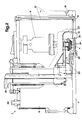
- 1 denotes in its entirety a header of the type used for filling, under sterile conditions, flexible bags 5 equipped with mouths 4.
- header can be used also for containers which have not been previously sterilised for filling in normal conditions.
- the header 1 comprises a sterile chamber 6 having either square or circular transversal section and inferiorly equipped with an aperture 3 through which the mouth 4 of a container is inserted.
- the chamber 6 may slide vertically between guides 16 by means of a couple of pistons 17, possibly substituted by a single piston.
- a cylindrical tubular element 18 is sealedly inserted which houses a filler valve 2 equipped with a central stem 10.
- a sort of bell 11 is fixed to the part of the tubular element 18 which is internal to the chamber 6, into which bell 11 a product feeder conduit 21 is laterally inserted.
- a union 9 is fixed by means of screws 19 to the said bell 11, which union 9 is interchangeable in cases where changes of mouth-shapes are made.
- the stem 10, too, is inferiorly equipped with an interchangeable union (8).
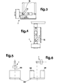
- a sealed joint 14 permits of the rotation of the header 1 and the filler valve 2 with respect to an external product feeder conduit 15.
- the said rotation is of about 90° and is such to allow the wall 7 of the chamber 6 having the aperture 3 for the introduction of the mouth to be disposed in a substantially vertical position, so that the filler axis is horizontal.
- the joint 14 constitutes a means to permit of a 90° rotation of the header, illustrated in figures 3 to 6.
- 12 denotes an aspirating tube for the liquid accumulated in a collecting groove 13, positioned in proximity to the edges of the chamber 6.
- the aspirating tube 12 can be external to the chamber 6 so that it is easily removable.
- the aspirating tube 12 is in this case inserted into a sleeve 31 which connects it to a suction conduit in the collecting groove 13.
- the tube 12 and the groove 13 constitute aspirating and discharging means for the condensation or liquid collected in the chamber 6.
- Said means are particularly important in that in this way dripping of the vapour or sterilising fluid is avoided, and thus corrosion of the metallic outer containers in which the bags 5 are normally housed is also avoided, as is the fouling of the bags 5 themselves.
- the chamber 6 houses also a second bell 22, which bell 22 is turn houses internally gripping means 32 for the extraction of the stopper from the mouth; said bell 22 permits of effecting sterilisation in a smaller space 37 with respect to the entire chamber 6.
- the bell 22 through means which permit of its lifting and rotation, can be raised up to a position indicated by a dotted line in figure 2, and can be moved into another position internally to the chamber 6 to allow the first bell 11 to be lowered.
- the space 37 of considerably smaller volume than the entire chamber can be sterilised by means of the immission of steam or other sterilising fluid.
- the steam or sterilising fluid enters into the bell 22 through a conduit 33 which finishes in a plurality of nozzles 34 arranged on an interchangeable ring 35.
- Figures 5 and 6 illustrate respectively, the cases of a single large bag of about 1000kg of product housed in a container and transported on a pallet 23 to below the header 1, and of four containers 38 on pallets (of which only two are illustrated) each of which containers 38 houses a bag which bag can contain up to 200-250 kg of product.
- the particular position of the joint 14, that is, the centre of rotation of the header 1 is such that when the header 1 has its filling axis vertical it is able to fill the 1000 kg bag, whereas when it is turned so that its filling axis is horizontal, it is able to fill the four 200-250 bags automatically.
- the support pallet 23 performs 90° rotations between consecitive fillings in such a way that it brings each bag in turn into the correct filling position below the header 1.
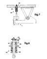
- 24 denotes a suspension device for the header 1 with its filling axis substantially horizontal, applicable in the case of bags able to contain up to 200-250 kg of product.
- the device 24 comprises a piston 25, connected inferiorly to the header 1 and slidable internally to a cylindrical body 27, in which it is kept elastically pressed upwards by a spring 26.
- a threaded closing element 28 is inferiorly screwed into the body 27, which closing element 28 regulates the spring 26 loading.
- the header 1 is held upwards to permit the bag to remain partially raised from the bottom of the container in which it is inserted.
- the device 24 makes uniform and complete filling of the bags possible, without the need for the intervention of an operator to keep the bag raised at the beginning with respect to its container.
Landscapes
- Engineering & Computer Science (AREA)
- Mechanical Engineering (AREA)
- Basic Packing Technique (AREA)
- Filling Of Jars Or Cans And Processes For Cleaning And Sealing Jars (AREA)
Applications Claiming Priority (2)
| Application Number | Priority Date | Filing Date | Title |
|---|---|---|---|
| ITPR910007A IT1249122B (it) | 1991-02-19 | 1991-02-19 | Testata operatrice, in macchina riempitrice di sacchi flessibili in ambiente asettico. |
| ITPR910007 | 1991-02-19 |
Publications (1)
| Publication Number | Publication Date |
|---|---|
| EP0500501A1 true EP0500501A1 (de) | 1992-08-26 |
Family
ID=11395617
Family Applications (1)
| Application Number | Title | Priority Date | Filing Date |
|---|---|---|---|
| EP92830007A Withdrawn EP0500501A1 (de) | 1991-02-19 | 1992-01-10 | Füllkopf zum Füllen flexibler Beutel unter sterilen Bedingungen |
Country Status (3)
| Country | Link |
|---|---|
| EP (1) | EP0500501A1 (de) |
| CA (1) | CA2060706A1 (de) |
| IT (1) | IT1249122B (de) |
Cited By (1)
| Publication number | Priority date | Publication date | Assignee | Title |
|---|---|---|---|---|
| DE19526510A1 (de) * | 1995-07-20 | 1997-02-06 | Waldner Gmbh & Co Hermann | Automatisches Transfersystem |
Citations (4)
| Publication number | Priority date | Publication date | Assignee | Title |
|---|---|---|---|---|
| EP0088735A1 (de) * | 1982-03-10 | 1983-09-14 | EL.PO S.r.L. | Abfüllapparat für Behälter mit flüssigen/pastösen Substanzen unter sterilen Bedingungen |
| EP0115963A1 (de) * | 1983-02-04 | 1984-08-15 | Scholle Corporation | Füllvorrichtung für Behälter |
| US4524563A (en) * | 1981-12-10 | 1985-06-25 | Tito Manzini & Figli S.P.A. | Process and plant for aseptic filling of pre-sterilized, non-rigid containers |
| US4893733A (en) * | 1988-11-22 | 1990-01-16 | Thomsen Peter N | Filling head with quick-change nozzle |
-
1991
- 1991-02-19 IT ITPR910007A patent/IT1249122B/it active IP Right Grant
-
1992
- 1992-01-10 EP EP92830007A patent/EP0500501A1/de not_active Withdrawn
- 1992-02-05 CA CA002060706A patent/CA2060706A1/en not_active Abandoned
Patent Citations (4)
| Publication number | Priority date | Publication date | Assignee | Title |
|---|---|---|---|---|
| US4524563A (en) * | 1981-12-10 | 1985-06-25 | Tito Manzini & Figli S.P.A. | Process and plant for aseptic filling of pre-sterilized, non-rigid containers |
| EP0088735A1 (de) * | 1982-03-10 | 1983-09-14 | EL.PO S.r.L. | Abfüllapparat für Behälter mit flüssigen/pastösen Substanzen unter sterilen Bedingungen |
| EP0115963A1 (de) * | 1983-02-04 | 1984-08-15 | Scholle Corporation | Füllvorrichtung für Behälter |
| US4893733A (en) * | 1988-11-22 | 1990-01-16 | Thomsen Peter N | Filling head with quick-change nozzle |
Cited By (1)
| Publication number | Priority date | Publication date | Assignee | Title |
|---|---|---|---|---|
| DE19526510A1 (de) * | 1995-07-20 | 1997-02-06 | Waldner Gmbh & Co Hermann | Automatisches Transfersystem |
Also Published As
| Publication number | Publication date |
|---|---|
| IT1249122B (it) | 1995-02-11 |
| CA2060706A1 (en) | 1992-08-20 |
| ITPR910007A0 (it) | 1991-02-19 |
| ITPR910007A1 (it) | 1992-08-19 |
Similar Documents
| Publication | Publication Date | Title |
|---|---|---|
| EP0955240B1 (de) | Vorrichtung zum aseptischen Füllen mit hoher Geschwindigkeit | |
| US9540123B2 (en) | Packaging machine and method for filling bags | |
| EP2569217B1 (de) | Verfahren und vorrichtung zum befüllen von behältern | |
| RU2244666C2 (ru) | Способ одновременного наполнения контейнеров (варианты) | |
| US4648233A (en) | Apparatus for handling liquid filled flexible plastic bags | |
| EP3125953B1 (de) | Sterilisiermaschine für lose produkte | |
| EP0758624A1 (de) | Anlage zum sterilen Füllen von Flaschen im Durchlaufverfahren | |
| JPH02159277A (ja) | 無菌充填装置および方法 | |
| CN102015456A (zh) | 用于接收容器和盖及用于封闭容器的抓取装置 | |
| CN210974703U (zh) | 细胞批量自动化生产设备 | |
| US6736172B1 (en) | Filling machine comprising having at least one chamber enclosure with a controlled atmosphere | |
| EP1431182B1 (de) | System für Höhenverstellung einer Förderstation die Artikeln zu einer Verpackungsmaschine fördert | |
| US6817969B2 (en) | Carton puller vacuum head and method | |
| EP0207647A2 (de) | Verfahren und Vorrichtung zur Ausführung von Handlungen auf einer Behälterhülse | |
| US5533550A (en) | Tank venting apparatus for a packaging machine | |
| CN214420801U (zh) | 一种茶叶充氮保鲜装置 | |
| EP3757025A1 (de) | Anlage zum behandeln von behältern, die dafür ausgelegt sind, ein fliessfähiges produkt zu enthalten | |
| CN207826685U (zh) | 一种平板培养基灌装线的开盖装置 | |
| EP0648676B1 (de) | Verstellbare Behälterrückführung für ein Hebesystem mit veränderlichem Hub in einer Verpackungsmaschine | |
| WO1991015401A1 (en) | Method and apparatus for filling a container in a sterile fashion | |
| EP2695847A1 (de) | Maschine zur automatischen und hygienischen leerung von trommeln | |
| GB2069060A (en) | Dispensing viscous substances | |
| CN222408789U (zh) | 一种灌装机夹持机构 | |
| RU97107010A (ru) | Вентилирование резервуара упаковочной машины | |
| EP0515077B1 (de) | Zusammenstellung von Füllstutzen und Ventil |
Legal Events
| Date | Code | Title | Description |
|---|---|---|---|
| PUAI | Public reference made under article 153(3) epc to a published international application that has entered the european phase |
Free format text: ORIGINAL CODE: 0009012 |
|
| AK | Designated contracting states |
Kind code of ref document: A1 Designated state(s): CH DE ES FR GR LI NL PT |
|
| DX | Miscellaneous (deleted) | ||
| 17P | Request for examination filed |
Effective date: 19921223 |
|
| 17Q | First examination report despatched |
Effective date: 19940228 |
|
| 18D | Application deemed to be withdrawn |
Effective date: 19940712 |