EP0499900B1 - Two-stage high flow purge valve - Google Patents
Two-stage high flow purge valve Download PDFInfo
- Publication number
- EP0499900B1 EP0499900B1 EP92102033A EP92102033A EP0499900B1 EP 0499900 B1 EP0499900 B1 EP 0499900B1 EP 92102033 A EP92102033 A EP 92102033A EP 92102033 A EP92102033 A EP 92102033A EP 0499900 B1 EP0499900 B1 EP 0499900B1
- Authority
- EP
- European Patent Office
- Prior art keywords
- valve
- high flow
- outlet port
- flow orifice
- flow
- Prior art date
- Legal status (The legal status is an assumption and is not a legal conclusion. Google has not performed a legal analysis and makes no representation as to the accuracy of the status listed.)
- Expired - Lifetime
Links
Images



Classifications
-
- F—MECHANICAL ENGINEERING; LIGHTING; HEATING; WEAPONS; BLASTING
- F02—COMBUSTION ENGINES; HOT-GAS OR COMBUSTION-PRODUCT ENGINE PLANTS
- F02M—SUPPLYING COMBUSTION ENGINES IN GENERAL WITH COMBUSTIBLE MIXTURES OR CONSTITUENTS THEREOF
- F02M25/00—Engine-pertinent apparatus for adding non-fuel substances or small quantities of secondary fuel to combustion-air, main fuel or fuel-air mixture
- F02M25/08—Engine-pertinent apparatus for adding non-fuel substances or small quantities of secondary fuel to combustion-air, main fuel or fuel-air mixture adding fuel vapours drawn from engine fuel reservoir
- F02M25/0836—Arrangement of valves controlling the admission of fuel vapour to an engine, e.g. valve being disposed between fuel tank or absorption canister and intake manifold
-
- F—MECHANICAL ENGINEERING; LIGHTING; HEATING; WEAPONS; BLASTING
- F02—COMBUSTION ENGINES; HOT-GAS OR COMBUSTION-PRODUCT ENGINE PLANTS
- F02M—SUPPLYING COMBUSTION ENGINES IN GENERAL WITH COMBUSTIBLE MIXTURES OR CONSTITUENTS THEREOF
- F02M25/00—Engine-pertinent apparatus for adding non-fuel substances or small quantities of secondary fuel to combustion-air, main fuel or fuel-air mixture
- F02M25/08—Engine-pertinent apparatus for adding non-fuel substances or small quantities of secondary fuel to combustion-air, main fuel or fuel-air mixture adding fuel vapours drawn from engine fuel reservoir
- F02M2025/0845—Electromagnetic valves
-
- Y—GENERAL TAGGING OF NEW TECHNOLOGICAL DEVELOPMENTS; GENERAL TAGGING OF CROSS-SECTIONAL TECHNOLOGIES SPANNING OVER SEVERAL SECTIONS OF THE IPC; TECHNICAL SUBJECTS COVERED BY FORMER USPC CROSS-REFERENCE ART COLLECTIONS [XRACs] AND DIGESTS
- Y10—TECHNICAL SUBJECTS COVERED BY FORMER USPC
- Y10S—TECHNICAL SUBJECTS COVERED BY FORMER USPC CROSS-REFERENCE ART COLLECTIONS [XRACs] AND DIGESTS
- Y10S137/00—Fluid handling
- Y10S137/907—Vacuum-actuated valves
-
- Y—GENERAL TAGGING OF NEW TECHNOLOGICAL DEVELOPMENTS; GENERAL TAGGING OF CROSS-SECTIONAL TECHNOLOGIES SPANNING OVER SEVERAL SECTIONS OF THE IPC; TECHNICAL SUBJECTS COVERED BY FORMER USPC CROSS-REFERENCE ART COLLECTIONS [XRACs] AND DIGESTS
- Y10—TECHNICAL SUBJECTS COVERED BY FORMER USPC
- Y10T—TECHNICAL SUBJECTS COVERED BY FORMER US CLASSIFICATION
- Y10T137/00—Fluid handling
- Y10T137/8593—Systems
- Y10T137/87265—Dividing into parallel flow paths with recombining
Definitions
- the present invention relates to evaporative emission control systems for vehicles and in particular to a purge valve that is adapted to be controlled by the engine management control system for regulating the supply of fuel vapors to the engine intake from the fuel tank vapor recovery system.
- present day vehicles contain evaporative emission control systems which reduce the quantity of gasoline vapors emanating from the fuel tank of the vehicle.
- these systems include a charcoal canister which traps the vapors from the fuel tank, and a purge system which draws the vapors out of the canister and feeds them into the intake system of the engine when the engine is running. The fuel vapors are drawn into the engine intake manifold along with atmospheric air drawn through the canister.
- the capability of the canister to trap vapors from the fuel tank is greatly dependent upon how thoroughly the vapors are purged from the canister when the vehicle was last operated. Accordingly, it is desirable to purge the canister as much as possible while the engine is running.
- the amount of vapor that can be drawn into the engine at any time is limited by the total airflow into the engine and the accuracy with which the purge flow can be controlled.
- high purge flow rates can be easily handled. Under such conditions, however, the manifold vacuum is low which tends to limit the amount of fuel vapors and air which can be drawn from the canister into the engine intake manifold. In addition, when the engine is at idle, the airflow into the engine is low.
- purging at idle must be precisely controlled to prevent a rough idle.
- purging during idle can significantly impact the resulting air/flow ratio of the fuel mixture supplied to the engine. Consequently, purging at idle can easily result in a too rich or too lean fuel mixture causing excessive tailpipe emissions unless purging at idle is limited to low flow rates.
- Current emissions systems therefore, do not generally purge the canister at idle to any substantial degree.
- the purge control valve must be capable of allowing the engine control computer to precisely control small flow rates at idle while correcting the idle fuel-air ratio so that tailpipe emissions are not adversely affected. This type of precise flow control is best accomplished using a relatively small valve.
- the valve according to the invention includes a single assembly having two valves which control separate parallel flow paths.
- Low flow control is achieved with a small solenoid valve adapted to be driven by a pulse width modulated (PWM) signal from the engine control computer.
- High flow capacity is provided by a vacuum-controlled valve which opens at low manifold vacuum pressures. Because purge flow comprises a relatively small percentage of total air flow into the engine under the conditions with the high flow stages open, precise control of the high flow capacity valve by the engine control computer is not required.
- the purge valve allows the full range from 10 percent to 90 percent duty cycle control to be used to control low flow rates and opens the high flow valve only when the purge flow comprises a small portion of the total engine intake air flow.
- the high flow valve is adapted to open gradually as engine manifold vacuum pressure decreases, thereby proportioning the purge flow to the total engine intake air flow.
- the engine control computer can still adjust the high purge flow rate to a degree by controlling the parallel flow through the PWM solenoid valve.
- the response and flow capacity of both the low and high flow control valves can be calibrated to meet the requirements of a particular engine family or purge system.
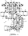
- FIG. 1 a sectional view of a two-stage high flow purge valve 10 according to the present invention is shown.
- the purge valve 10 is adapted to be connected between the intake system of the engine of the vehicle and the charcoal canister which traps fuel vapors from the fuel tank: of the vehicle.
- the purge valve 10 is responsive to engine manifold vacuum pressures and is also adapted to be controlled by the engine control computer to regulate the rate at which fuel vapors are drawn from the charcoal canister into the engine intake manifold.
- the purge valve 10 comprises a valve body 12 having an inlet port 14 adapted for connection to the charcoal canister and an outlet port 16 adapted for connection to the engine intake manifold. Hence, a negative pressure or vacuum is present at outlet port 16 when the vehicle engine is operating which serves to draw fuel vapors from the charcoal canister as permitted by the purge valve 10.
- the purge valve 10 controls the flow of vapors from the canister to the engine intake via two valve structures which control separate parallel flow paths through the valve body 12.
- the present two-stage purge valve 10 includes a small solenoid valve 18 for providing precise low flow control and a vacuum-controlled valve 20 for providing high flow capacity.
- the solenoid valve 18 controls purge flow from the inlet port 14 to the outlet port 16 through a first low flow orifice 26 in the valve body 12.
- the vacuum-controlled valve 20 controls purge flow from the inlet port 14 to the outlet port 16 through a second high flow orifice 24 in the valve body 12.
- the solenoid valve 18 comprises a solenoid coil 28 that is wrapped around a bobbin 30 having a central bore containing a pole piece 32 and a movable armature 34.
- the ends of the coil windings 28 of the solenoid 18 are terminated at an electrical connector 22 that is adapted for electrical connection to the engine control computer of the vehicle.
- the return flux path for the solenoid is provided by a C-frame member that is secured to the pole piece at one end 37 and has an opening 35 formed in its other end through which the armature 34 extends to thereby permit axial movement of the armature 34.
- the armature 34 has attached to its exposed end an elastic member 38 which is adapted to seal valve seat 25 which controls the flow through low flow orifice 26 in the valve body 12.
- a small compression spring 40 is disposed within a bore 41 formed in the opposite end of the armature 34 between the pole piece 32 and the armature 34 to bias the armature 34 into the normally closed position illustrated in Figure 1.
- a pad 42 is provided on the end of the pole piece 32 opposite the armature 34 to absorb the impact of the armature 34 and quiet the sound of the solenoid when the armature is attracted to the pole piece 32 when the solenoid 18 is energized.
- the solenoid valve 18 is adapted to operate in response to a pulse width modulated (PWM) signal received from the engine control computer.
- PWM pulse width modulated
- the duty cycle of the PWM signal received from the engine control computer will determine the rate of purge flow through orifice 26 in the valve body 12. Due to the relatively short stroke of the armature 34 of the solenoid valve 18, the rate of purge flow possible through orifice 26 in valve body 12 is relatively limited. On the other hand, the rapid response characteristics of the solenoid valve 18 permit the engine control computer to precisely regulate the purge flow through orifice 26.
- the high flow vacuum responsive valve 20 comprises a poppet valve 48 that includes a tapered pintle portion 49 that extends into the orifice 24 in the valve body.
- the pintle 49 thus ensures that the poppet valve 48 remains in proper alignment with the orifice 24.
- the position of the poppet valve 48 is controlled by a diaphragm 50 via a diaphragm guide member 52 that is attached to the diaphragm 50 and threadedly connected to the poppet valve 48.
- the diaphragm 50 is secured about its periphery to the valve body 12 via a cover 60 that is fastened to the valve body.
- a compression spring 54 is disposed between the valve body 12 and the diaphragm guide member 52 to bias the poppet valve 48 into its normally open position.
- An O-ring 56 is provided on the poppet valve and is adapted to seal against the tapered seat 58 of the orifice 24 in the valve body.
- the pintle portion 49 of poppet valve 48 is provided with a tapered shoulder portion 51 so that the purge flow through orifice 24 increases gradually with decreasing vacuum pressure.
- a degree of proportional control of purge flow through the high flow valve 20 is provided relative to the amount of vacuum pressure.
- other relationships between vacuum pressure and purge flow can be achieved by altering the configuration of the pintle 49.
- the preferred embodiment includes an additional valve element comprising a valve disc 64 which is positioned on the pintle end 49 of the poppet valve 48 by a compression spring 66.
- Valve element 64 is effective to close the purge flow passage through orifice 24 when the engine is turned off and the vacuum pressure at outlet port 16 is zero.
- the purpose of this additional valve 64 is to prevent the escape of fuel vapors from the canister through the purge valve 10, intake manifold, and air cleaner to atmosphere when the engine of the vehicle is turned off.
- the valve 64 is designed to open when the manifold vacuum pressure is at any level greater than approximately 0.03 bar (one inch of mercury). Accordingly, this allows full flow through the purge system at manifold vacuums of 0.07 to 0.1 bar (two to three inches of mercury).
- the end of the pole piece 32 opposite the armature 34 is threaded at 44 to the valve body 12 to permit axial adjustment of the position of the pole piece 32 which in turn determines the stroke of the armature 34 and hence the degree to which passageway 26 is opened.
- means are also preferably provided for calibrating the high flow vacuum-controlled valve 20 as well.
- the poppet valve 48 is, as noted 62 threaded to the diaphragm guide member 52 thereby permitting the axial position of the poppet valve 48 to be adjusted relative to the diaphragm 50 and guide member 52. Consequently, the degree to which the poppet valve 48 is opened, and hence the amount of purge flow through the high flow passage 24, can be calibrated to a given vacuum pressure level.
- Access for calibrating the position of the poppet valve 48 is provided through an opening 67 in the valve cover 60 which is then covered by a plug (now shown) when the calibration process is completed.
- FIG 4 a series of exemplary flow versus vacuum pressure curves at various duty cycles for the preferred embodiment of the present two-stage purge valve 10 is shown.
- the curves shown in Figure 4 represent the total combined purge flow through both valves 18 and 20 in the valve body 12. From a review of the flow curves, the operational characteristics of the present purge valve 10 are readily apparent. Firstly, it can be seen that at vacuum pressures above approximately 0.34 bar (ten inches of mercury), the high flow vacuum-controlled valve 20 is closed and purge flow through the valve body 12 is controlled exclusively by the PWM solenoid valve 18.
- FIG. 6 an alternative embodiment of the two-stage high flow purge valve 110 according to the present invention is shown.
- the diaphragm-controlled valve 120 and the solenoid valve 118 are located along the same axis.
- Components in the embodiment illustrated in Figure 6 that are functionally equivalent to the components described in the embodiment illustrated in Figures 1 - 3 are similarly numbered such that, for example, inlet port 14 and outlet port 16 in Figures 1 - 3 correspond to inlet port 114 and outlet port 116, respectively, in Figure 6.
- the valve body 112 and cover 160 in the embodiment illustrated in Figure 6 define an upper chamber 176 which communicates with outlet port 116 and a lower chamber 178 which communicates with inlet port 114.
- valve body 112 in this embodiment includes an integrally formed central stem portion 172 that extends upwardly into the upper chamber 176 and has formed therethrough a bore 126 which comprises the low flow orifice passageway.
- the high flow, vacuum-controlled valve 120 has been modified to provide a fixed valve member 148 and a movable orifice 124.
- the valve member 148 in this embodiment has a central bore 175 formed therein that is adapted to communicate with the bore 126 and the stem portion 172 of the valve body 112.
- the valve member 148 has an enlarged counterbore 174 that enables the valve member 148 to be mounted onto the stem 172.
- a seal 180 is provided at the base of the counterbore 174 to prevent air leakage between the valve member 148 and the stem 172 of the valve body.
- the stationary valve member 178 is adapted to cooperate with the movable orifice 124 formed in the diaphragm support member 152 attached to the diaphragm 150. Accordingly, when a high manifold vacuum pressure is present at outlet port 116, the support member 152 is moved upwardly by the diaphragm 150 against the bias of compression spring 154 until the O-ring 156 on the valve member 148 seals against the chamfered seat 158 surrounding orifice 124.
- the diaphragm 150 in this embodiment includes an annular-shaped raised rib 164 that is adapted to seal against the wall 171 of the valve body 112 separating the upper chamber 176 from the lower chamber 178 to thereby close the high flow valve 120 when the engine is off and the manifold vacuum pressure is zero.
- the annular-shaped rib 164 on the diaphragm serves the equivalent function of the valve member 64 in the embodiment illustrated in Figures 1 - 3.
- the solenoid valve 118 in the lower chamber 178 of the valve body 112 and hence within the purge flow path, a means of cooling the solenoid coil 118 is provided.
- the inlet and outlet ports 114 and 116 may be located on the sides of the valve housing 112 if packaging requirements of a particular application dictate such a configuration.
Landscapes
- Engineering & Computer Science (AREA)
- Chemical & Material Sciences (AREA)
- Combustion & Propulsion (AREA)
- Mechanical Engineering (AREA)
- General Engineering & Computer Science (AREA)
- Supplying Secondary Fuel Or The Like To Fuel, Air Or Fuel-Air Mixtures (AREA)
- Magnetically Actuated Valves (AREA)
Description
- The present invention relates to evaporative emission control systems for vehicles and in particular to a purge valve that is adapted to be controlled by the engine management control system for regulating the supply of fuel vapors to the engine intake from the fuel tank vapor recovery system.
- In order to meet current emission requirements, present day vehicles contain evaporative emission control systems which reduce the quantity of gasoline vapors emanating from the fuel tank of the vehicle. Generally, these systems include a charcoal canister which traps the vapors from the fuel tank, and a purge system which draws the vapors out of the canister and feeds them into the intake system of the engine when the engine is running. The fuel vapors are drawn into the engine intake manifold along with atmospheric air drawn through the canister.
- The capability of the canister to trap vapors from the fuel tank is greatly dependent upon how thoroughly the vapors are purged from the canister when the vehicle was last operated. Accordingly, it is desirable to purge the canister as much as possible while the engine is running. However, the amount of vapor that can be drawn into the engine at any time is limited by the total airflow into the engine and the accuracy with which the purge flow can be controlled. At high speeds or under high engine loads, high purge flow rates can be easily handled. Under such conditions, however, the manifold vacuum is low which tends to limit the amount of fuel vapors and air which can be drawn from the canister into the engine intake manifold. In addition, when the engine is at idle, the airflow into the engine is low. Therefore, purging at idle must be precisely controlled to prevent a rough idle. Moreover, due to the varying ratio of air to fuel vapors in the purge system, purging during idle can significantly impact the resulting air/flow ratio of the fuel mixture supplied to the engine. Consequently, purging at idle can easily result in a too rich or too lean fuel mixture causing excessive tailpipe emissions unless purging at idle is limited to low flow rates. Current emissions systems, therefore, do not generally purge the canister at idle to any substantial degree.
- However, impending tighter emissions requirements and changes to the testing procedures will require larger capacity canisters and therefore higher capacity purge systems. Moreover, the prospect of on-board refueling vapor recovery systems will only add to these system requirements. Accordingly, it is becoming imperative that such systems not only purge at idle, but that maximum flow rates be increased as well. This, of course, presents conflicting requirements for purge systems. Specifically, in order to purge at idle, the purge flow rate must be fairly low and accurately controlled by the engine control computer which monitors the resulting oxygen content of the exhaust gases from the engine. When a canister is saturated with fuel, and vapor is initially purged, the purge flow is very high in fuel vapor. After most of the fuel vapors are drawn out of the charcoal, the purge flow is almost pure air. Therefore, the purge control valve must be capable of allowing the engine control computer to precisely control small flow rates at idle while correcting the idle fuel-air ratio so that tailpipe emissions are not adversely affected. This type of precise flow control is best accomplished using a relatively small valve.
- On the other hand, it is desirable to purge at high flow rates when the engine is operating under high speed or heavy load conditions when it can efficiently consume significant quantities of fuel vapor and air with a minium effect on fuel air ratios. In order to achieve large flow rates, it is necessary for the purge valve to provide relatively large flow passage. This requirement, of course, is in direct conflict with the requirement for precise low flow rate control. Specifically, it is believed to be impractical to provide a valve large enough to satisfy the high flow requirements which at the same time is capable of precisely modulating the opening of the valve to meet the low flow requirements.
- From WO-A-91 17353 which was published after the priority date of the current application, but which enjoys with respect to the parts that are disclosed in the priority document US-517,285 a better priority than the current application (Articles 54 (3) and (4), 88 (3) and 89 EPC), a two-stage valve for a vehicle having an internal combustion engine is known which comprises:
- a valve body defining an inlet port adapted for connection to a source of fluid and an outlet port adapted for connection to a source of vacuum;
- a high flow orifice defining a first flow path through said valve body from said inlet port to said outlet port;
- a low flow orifice defining a second flow path through said valve body from said inlet port to said outlet port in parallel with said first flow path;
- first valve means for controlling the fluid flow through said high flow orifice; and
- second valve means comprising a solenoid valve for controlling the fluid flow through said low flow orifice in response to an electrical signal supplied to said solenoid valve.
- Furtherthemore, the document DE-C-40 03 036 discloses a two-stage valve according to the preamble of
claim 1. - It is the primary object of the present invention to provide a two-stage purge control valve that is capable of providing both precise control at low flow rates and high flow capacity at low manifold vacuum pressures.
- This object is achieved by a two-stage valve according to
claim 1. - The valve according to the invention includes a single assembly having two valves which control separate parallel flow paths. Low flow control is achieved with a small solenoid valve adapted to be driven by a pulse width modulated (PWM) signal from the engine control computer. High flow capacity is provided by a vacuum-controlled valve which opens at low manifold vacuum pressures. Because purge flow comprises a relatively small percentage of total air flow into the engine under the conditions with the high flow stages open, precise control of the high flow capacity valve by the engine control computer is not required.
- Accordingly, the purge valve, according to the present invention allows the full range from 10 percent to 90 percent duty cycle control to be used to control low flow rates and opens the high flow valve only when the purge flow comprises a small portion of the total engine intake air flow. Moreover, the high flow valve is adapted to open gradually as engine manifold vacuum pressure decreases, thereby proportioning the purge flow to the total engine intake air flow. In addition, the engine control computer can still adjust the high purge flow rate to a degree by controlling the parallel flow through the PWM solenoid valve.
- In the preferred embodiment of the present invention, the response and flow capacity of both the low and high flow control valves can be calibrated to meet the requirements of a particular engine family or purge system.
- Additional objects and advantages of the present invention will become apparent from a reading of the following description of the preferred embodiments which make reference to the drawings of which:
- Figure 1 is a sectional view of a two-stage purge valve according to the present invention with the valves in the closed position corresponding to the engine being off;
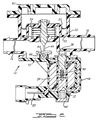
- Figure 2 is a sectional view of the two-stage purge valve shown in Figure 1 with the valves in the closed position corresponding to high engine manifold vacuum;
- Figure 3 is a sectional view of the two-stage purge valve shown in Figure 1 with the valves in the maximum flow position corresponding to low engine manifold vacuum;
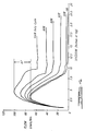
- Figure 4 is a graph of the flow versus vacuum pressure characteristics of the purge valve shown in Figure 1;
- Figure 5 is a graph of the flow versus percentage duty cycle characteristics of the two-stage purge valve shown in Figure 1; and
- Figure 6 is a sectional view of an alternative embodiment of the two-stage purge valve according to the present invention.
- Referring to Figure 1, a sectional view of a two-stage high
flow purge valve 10 according to the present invention is shown. Thepurge valve 10 is adapted to be connected between the intake system of the engine of the vehicle and the charcoal canister which traps fuel vapors from the fuel tank: of the vehicle. Thepurge valve 10 is responsive to engine manifold vacuum pressures and is also adapted to be controlled by the engine control computer to regulate the rate at which fuel vapors are drawn from the charcoal canister into the engine intake manifold. - The
purge valve 10 comprises avalve body 12 having aninlet port 14 adapted for connection to the charcoal canister and anoutlet port 16 adapted for connection to the engine intake manifold. Hence, a negative pressure or vacuum is present atoutlet port 16 when the vehicle engine is operating which serves to draw fuel vapors from the charcoal canister as permitted by thepurge valve 10. - The
purge valve 10 controls the flow of vapors from the canister to the engine intake via two valve structures which control separate parallel flow paths through thevalve body 12. In particular, the present two-stage purge valve 10 includes asmall solenoid valve 18 for providing precise low flow control and a vacuum-controlledvalve 20 for providing high flow capacity. Thesolenoid valve 18 controls purge flow from theinlet port 14 to theoutlet port 16 through a firstlow flow orifice 26 in thevalve body 12. The vacuum-controlledvalve 20 controls purge flow from theinlet port 14 to theoutlet port 16 through a secondhigh flow orifice 24 in thevalve body 12. - The
solenoid valve 18 comprises asolenoid coil 28 that is wrapped around abobbin 30 having a central bore containing apole piece 32 and amovable armature 34. The ends of thecoil windings 28 of thesolenoid 18 are terminated at anelectrical connector 22 that is adapted for electrical connection to the engine control computer of the vehicle. The return flux path for the solenoid is provided by a C-frame member that is secured to the pole piece at oneend 37 and has anopening 35 formed in its other end through which thearmature 34 extends to thereby permit axial movement of thearmature 34. Thearmature 34 has attached to its exposed end anelastic member 38 which is adapted toseal valve seat 25 which controls the flow throughlow flow orifice 26 in thevalve body 12. Asmall compression spring 40 is disposed within abore 41 formed in the opposite end of thearmature 34 between thepole piece 32 and thearmature 34 to bias thearmature 34 into the normally closed position illustrated in Figure 1. Apad 42 is provided on the end of thepole piece 32 opposite thearmature 34 to absorb the impact of thearmature 34 and quiet the sound of the solenoid when the armature is attracted to thepole piece 32 when thesolenoid 18 is energized. - The
solenoid valve 18 is adapted to operate in response to a pulse width modulated (PWM) signal received from the engine control computer. In particular, the duty cycle of the PWM signal received from the engine control computer will determine the rate of purge flow throughorifice 26 in thevalve body 12. Due to the relatively short stroke of thearmature 34 of thesolenoid valve 18, the rate of purge flow possible throughorifice 26 invalve body 12 is relatively limited. On the other hand, the rapid response characteristics of thesolenoid valve 18 permit the engine control computer to precisely regulate the purge flow throughorifice 26. - The high flow vacuum
responsive valve 20 comprises apoppet valve 48 that includes a taperedpintle portion 49 that extends into theorifice 24 in the valve body. Thepintle 49 thus ensures that thepoppet valve 48 remains in proper alignment with theorifice 24. The position of thepoppet valve 48 is controlled by adiaphragm 50 via adiaphragm guide member 52 that is attached to thediaphragm 50 and threadedly connected to thepoppet valve 48. Thediaphragm 50 is secured about its periphery to thevalve body 12 via acover 60 that is fastened to the valve body. Acompression spring 54 is disposed between thevalve body 12 and thediaphragm guide member 52 to bias thepoppet valve 48 into its normally open position. An O-ring 56 is provided on the poppet valve and is adapted to seal against the taperedseat 58 of theorifice 24 in the valve body. - In operation, when the vehicle engine is idling, a high degree of vacuum pressure is present at
outlet port 16, thereby drawingdiaphragm 50 downwardly causing O-ring 56 to seal againstseat 58 and closing thehigh flow valve 20, as shown in Figure 2. As previously noted, as engine speed or engine loading increases, the amount of vacuum pressure decreases. As engine speed increases off idle, therefore, a point is reached whereby the vacuum pressure atoutlet port 16 is no longer sufficient to hold thepoppet valve 48 in the closed position against the force ofcompression spring 54 andpoppet valve 48 begins to open. In the preferred embodiment, this point corresponds to a vacuum pressure of approximately 0.34 bar (ten inches of mercury). As vacuum pressure decreases further, thepoppet valve 48 continues to open thereby permitting increased purge flow throughorifice 24 invalve body 12. Under high engine load conditions when manifold vacuum is lowest (e.g., 0.07-0.1 bar, corresponding to 2 - 3 inches of mercury), the vacuum pressure atoutlet port 16 can only compressspring 54 slightly as shown in Figure 3, thereby maximizing the purge flow throughorifice 24. To summarize, therefore, at or near engine idle when vacuum pressure is highest,poppet valve 48 is in the closed position shown in Figure 2, and at high engine loads when vacuum pressure is lowest,poppet valve 48 is in the fully open position shown in Figure 3. - Preferably, the
pintle portion 49 ofpoppet valve 48 is provided with atapered shoulder portion 51 so that the purge flow throughorifice 24 increases gradually with decreasing vacuum pressure. In this manner, a degree of proportional control of purge flow through thehigh flow valve 20 is provided relative to the amount of vacuum pressure. However, it will be appreciated that other relationships between vacuum pressure and purge flow can be achieved by altering the configuration of thepintle 49. - In addition, the preferred embodiment includes an additional valve element comprising a
valve disc 64 which is positioned on thepintle end 49 of thepoppet valve 48 by acompression spring 66.Valve element 64 is effective to close the purge flow passage throughorifice 24 when the engine is turned off and the vacuum pressure atoutlet port 16 is zero. The purpose of thisadditional valve 64 is to prevent the escape of fuel vapors from the canister through thepurge valve 10, intake manifold, and air cleaner to atmosphere when the engine of the vehicle is turned off. To ensure that thisadditional valve 64 does not otherwise adversely affect the purge flow, thevalve 64 is designed to open when the manifold vacuum pressure is at any level greater than approximately 0.03 bar (one inch of mercury). Accordingly, this allows full flow through the purge system at manifold vacuums of 0.07 to 0.1 bar (two to three inches of mercury). - In order to permit the
solenoid valve 18 to be accurately calibrated so as to provide a predetermined purge flow for a given duty cycle control signal, the end of thepole piece 32 opposite thearmature 34 is threaded at 44 to thevalve body 12 to permit axial adjustment of the position of thepole piece 32 which in turn determines the stroke of thearmature 34 and hence the degree to whichpassageway 26 is opened. Once thesolenoid valve 18 is calibrated, the access opening to the pole piece is covered by acap lock 46. - In addition, means are also preferably provided for calibrating the high flow vacuum-controlled
valve 20 as well. In particular, thepoppet valve 48 is, as noted 62 threaded to thediaphragm guide member 52 thereby permitting the axial position of thepoppet valve 48 to be adjusted relative to thediaphragm 50 and guidemember 52. Consequently, the degree to which thepoppet valve 48 is opened, and hence the amount of purge flow through thehigh flow passage 24, can be calibrated to a given vacuum pressure level. Access for calibrating the position of thepoppet valve 48 is provided through anopening 67 in thevalve cover 60 which is then covered by a plug (now shown) when the calibration process is completed. - Turning now to Figure 4, a series of exemplary flow versus vacuum pressure curves at various duty cycles for the preferred embodiment of the present two-
stage purge valve 10 is shown. The curves shown in Figure 4 represent the total combined purge flow through bothvalves valve body 12. From a review of the flow curves, the operational characteristics of thepresent purge valve 10 are readily apparent. Firstly, it can be seen that at vacuum pressures above approximately 0.34 bar (ten inches of mercury), the high flow vacuum-controlledvalve 20 is closed and purge flow through thevalve body 12 is controlled exclusively by thePWM solenoid valve 18. Secondly, it can be seen that even under high flow, low vacuum conditions when the vacuum-controlledvalve 20 is fully opened, the engine control computer retains a substantial range of control over total purge flow via control of thePWM solenoid valve 18. This minimum control range available to the engine control computer is designated "ΔF" in the diagram. Thirdly, the curves clearly demonstrate a substantially linear relationship between vacuum pressure and purge flow below approximately 0.27 bar (eight inches of mercury) where the taperedshoulder portion 51 of thepintle 49 controls the size of the opening throughvalve orifice 24. Accordingly, it can be seen that the vacuum-controlledvalve 20 varies purge flow progressively with changes in vacuum pressure. However, as previously noted, other relationships can be achieved in this region by varying the shape of thepintle 49. - With additional reference to Figure 5, a series of curves illustrating the relationship between total purge flow and percentage duty cycle at various vacuum pressure levels is shown. These curves also clearly demonstrate that above vacuum pressures of approximately 0.34 bar (ten inches of mercury), total flow through the
valve body 12 is governed exclusively by thePWM solenoid valve 18. In addition, the two upper curves illustrate the range of flow control ("ΔF") available to the engine control computer via control of thePWM solenoid valve 18 at vacuum pressures of 0.1 and 0.17 bar (three inches and five inches of mercury) when substantial purge flow exists through the vacuum-controlledvalve 20. - Referring to Figure 6, an alternative embodiment of the two-stage high
flow purge valve 110 according to the present invention is shown. In this embodiment, the diaphragm-controlledvalve 120 and thesolenoid valve 118 are located along the same axis. Components in the embodiment illustrated in Figure 6 that are functionally equivalent to the components described in the embodiment illustrated in Figures 1 - 3 are similarly numbered such that, for example,inlet port 14 andoutlet port 16 in Figures 1 - 3 correspond toinlet port 114 andoutlet port 116, respectively, in Figure 6. Thevalve body 112 and cover 160 in the embodiment illustrated in Figure 6 define anupper chamber 176 which communicates withoutlet port 116 and alower chamber 178 which communicates withinlet port 114. An annular-shapedpassageway 170 is formed in the valve body to provide communication between theupper chamber 176 and thelower chamber 178. Thevalve body 112 in this embodiment includes an integrally formed central stem portion 172 that extends upwardly into theupper chamber 176 and has formed therethrough abore 126 which comprises the low flow orifice passageway. - In addition, it will be noted that the high flow, vacuum-controlled
valve 120 has been modified to provide a fixedvalve member 148 and amovable orifice 124. In particular, thevalve member 148 in this embodiment has acentral bore 175 formed therein that is adapted to communicate with thebore 126 and the stem portion 172 of thevalve body 112. In addition, thevalve member 148 has an enlarged counterbore 174 that enables thevalve member 148 to be mounted onto the stem 172. Aseal 180 is provided at the base of the counterbore 174 to prevent air leakage between thevalve member 148 and the stem 172 of the valve body. Thestationary valve member 178 is adapted to cooperate with themovable orifice 124 formed in thediaphragm support member 152 attached to thediaphragm 150. Accordingly, when a high manifold vacuum pressure is present atoutlet port 116, thesupport member 152 is moved upwardly by thediaphragm 150 against the bias ofcompression spring 154 until the O-ring 156 on thevalve member 148 seals against thechamfered seat 158 surroundingorifice 124. - It will also be noted that the
diaphragm 150 in this embodiment includes an annular-shaped raisedrib 164 that is adapted to seal against thewall 171 of thevalve body 112 separating theupper chamber 176 from thelower chamber 178 to thereby close thehigh flow valve 120 when the engine is off and the manifold vacuum pressure is zero. In other words, the annular-shapedrib 164 on the diaphragm serves the equivalent function of thevalve member 64 in the embodiment illustrated in Figures 1 - 3. - Furthermore, by locating the
solenoid valve 118 in thelower chamber 178 of thevalve body 112 and hence within the purge flow path, a means of cooling thesolenoid coil 118 is provided. Optionally, the inlet andoutlet ports valve housing 112 if packaging requirements of a particular application dictate such a configuration.
Claims (10)
- A two-stage valve for a vehicle having an internal combustion engine, said valve comprising:- a valve body (12, 112) defining an inlet port (14, 114) adapted for connection to a source of fluid and an outlet port (16, 116) adapted for connection to a source of vacuum;- a high flow orifice (24, 124) defining a first flow path through said valve body (12, 112) from said inlet port (14, 114) to said outlet port (16, 116);- a low flow orifice (26, 126) defining a second flow path through said valve body (12, 112) from said inlet port (14, 114) to said outlet port (16, 116) in parallel with said first flow path;- first valve means (20) for controlling the fluid flow through said high flow orifice (24, 124); and- second valve means comprising a solenoid valve (18, 118) for controlling the fluid flow through said low flow orifice (26, 126) in response to an electrical signal supplied to said solenoid valve (18, 118);characterized in that- said first valve means (20) includes a diaphragm (50, 150) which continuously and directly is responsive to the level of vacuum pressure at said outlet port (16, 116) opening with decreasing vacuum pressure at said outlet port (16, 116).
- The two-stage valve according to claim 1, characterized in that said first valve means (20) is adapted to close said high flow orifice (24, 124) at vacuum pressures above a predetermined level and to open said high flow orifice (24, 124) at vacuum pressures below that predetermined level.
- The two-stage valve according to claims 1 or 2, characterized in that said first valve means (20) is adapted to progressively open said high flow orifice (24, 124) as vacuum pressure decreases below said predetermined level such that the fluid flow rate through said high flow orifice (24, 124) varies proportionally with changes in vacuum pressure.
- The two-stage valve according to anyone of claims 1 through 3, characterized by further including third valve means (64, 164) for blocking said first flow path when the engine is not running.
- The two-stage valve according to claim 4, characterized in that said third valve means (64, 164) is operatively associated with said first valve means (20) for blocking said first flow path when the vacuum pressure at said outlet port (16, 116) is substantially equal to zero.
- The two-stage valve according to anyone of claims 1 through 5, characterized in that said selenoid valve (18) comprises a fast-acting, on/off solenoid valve that is adapted to be controlled by a pulse width modulated electrical signal for precisely controlling the fluid flow through said low flow orifice (26, 126).
- The two-stage valve according to anyone of claims 1 through 6, characterized in that said first valve means (20) includes a valve member (48, 148) having a pintle portion (49) that extends into said high flow orifice (24, 124) for controlling the size of said high flow orifice (24, 124).
- The two-stage valve according to claim 7, characterized in that said third valve means (64, 164) is actuated by said pintle portion (49) of said valve member (48, 148).
- The two-stage valve according to claims 7 or 8, characterized in that said first valve means (20) further includes said diaphragm (50, 150) connected to said valve member (48, 148) and a bias member (54, 154) acting on said diaphragm (50, 150) against the force of vacuum pressure at said outlet port (16, 116) for actuating said valve member (48, 148) to vary the size of said high flow orifice (24, 124) in accordance with the vacuum pressure at said outlet port (16, 116).
- The two-stage valve according to anyone of claims 7 through 9, characterized in that said pintle portion (49) has a tapered shoulder portion (51, 151) for progressively varying the size of said high flow orifice (24, 124) as said valve member (48, 148) is actuated.
Applications Claiming Priority (2)
| Application Number | Priority Date | Filing Date | Title |
|---|---|---|---|
| US07/656,510 US5083546A (en) | 1991-02-19 | 1991-02-19 | Two-stage high flow purge valve |
| US656510 | 2000-09-06 |
Publications (2)
| Publication Number | Publication Date |
|---|---|
| EP0499900A1 EP0499900A1 (en) | 1992-08-26 |
| EP0499900B1 true EP0499900B1 (en) | 1995-05-24 |
Family
ID=24633337
Family Applications (1)
| Application Number | Title | Priority Date | Filing Date |
|---|---|---|---|
| EP92102033A Expired - Lifetime EP0499900B1 (en) | 1991-02-19 | 1992-02-07 | Two-stage high flow purge valve |
Country Status (4)
| Country | Link |
|---|---|
| US (1) | US5083546A (en) |
| EP (1) | EP0499900B1 (en) |
| CA (1) | CA2055571C (en) |
| DE (1) | DE69202589T2 (en) |
Families Citing this family (51)
| Publication number | Priority date | Publication date | Assignee | Title |
|---|---|---|---|---|
| US5226398A (en) * | 1990-03-08 | 1993-07-13 | Siemens Automotive Limited | Regulated flow canister purge system |
| DE4023044A1 (en) * | 1990-07-20 | 1992-01-23 | Bosch Gmbh Robert | VALVE FOR THE DOSED ADMINISTRATION OF VOLATILIZED FUEL TO THE FUEL-AIR MIXTURE OF AN INTERNAL COMBUSTION ENGINE |
| DE4111259C1 (en) * | 1991-04-08 | 1992-04-23 | Fa. Carl Freudenberg, 6940 Weinheim, De | |
| US5183022A (en) * | 1991-07-16 | 1993-02-02 | Siemens Automotive Limited | Multi-slope canister purge solenoid valve |
| US5188141A (en) * | 1991-12-03 | 1993-02-23 | Siemens Automotive Limited | Vacuum boost valve |
| DE4139946C1 (en) * | 1991-12-04 | 1993-02-04 | Fa. Carl Freudenberg, 6940 Weinheim, De | |
| US5297578A (en) * | 1992-08-14 | 1994-03-29 | Tillotson, Ltd. | Automatic shutoff valve |
| US5320128A (en) * | 1992-11-12 | 1994-06-14 | Chlorinators Incorporated | Chlorinator with reduced number of components |
| US5277167A (en) * | 1993-02-04 | 1994-01-11 | Lectron Products, Inc. | Vapor management valve |
| US5289811A (en) * | 1993-05-10 | 1994-03-01 | General Motors Corporation | Purge control device |
| DE4329396A1 (en) * | 1993-09-01 | 1995-03-02 | Pierburg Gmbh | Electropneumatic control valve |
| US5437257A (en) * | 1994-02-28 | 1995-08-01 | General Motors Corporation | Evaporative emission control system with vent valve |
| US5513832A (en) * | 1994-04-22 | 1996-05-07 | Lectron Products, Inc. | Variable force solenoid valve |
| US5462253A (en) * | 1994-07-22 | 1995-10-31 | General Motors Corporation | Dual slope flow control valve |
| US5429099A (en) * | 1994-09-08 | 1995-07-04 | Lectron Products, Inc. | Anti-permeation filter for vapor management valve |
| US5538219A (en) * | 1994-12-16 | 1996-07-23 | Borg-Warner Automotive, Inc. | Reduced noise solenoid valve |
| US5509395A (en) * | 1995-03-31 | 1996-04-23 | Siemens Electric Limited | Canister purge flow regulator |
| US5630403A (en) * | 1996-06-13 | 1997-05-20 | Siemens Electric Limited | Force-balanced sonic flow emission control valve |
| US6105598A (en) * | 1996-06-14 | 2000-08-22 | United States Filter Corporation | Low capacity chlorine gas feed system |
| US5749349A (en) * | 1996-10-24 | 1998-05-12 | Eaton Corporation | Fuel vapor control system |
| US5970958A (en) * | 1997-10-10 | 1999-10-26 | Eaton Corporation | Fuel vapor purge control |
| US5967183A (en) * | 1998-01-13 | 1999-10-19 | Eaton Corporation | Controlling vapor flow in a conduit |
| US5941218A (en) * | 1998-03-20 | 1999-08-24 | Eaton Corporation | Welded construction for fuel vapor purge regulator valve assembly |
| US6308724B1 (en) | 1998-04-03 | 2001-10-30 | United States Filter Corporation | Low capacity chlorine gas feed system |
| DE19901090A1 (en) * | 1999-01-14 | 2000-07-20 | Bosch Gmbh Robert | Valve for the metered introduction of volatilized fuel |
| US6263900B1 (en) | 2000-02-17 | 2001-07-24 | United States Filter Corporation | Low capacity chlorine gas feed system |
| US6612338B2 (en) * | 2000-05-25 | 2003-09-02 | Siemens Automotive Inc. | Fuel tank pressure control valve |
| DE10034033A1 (en) * | 2000-07-13 | 2002-01-24 | Nass Magnet Gmbh | magnetic valve |
| US6763846B2 (en) * | 2001-08-20 | 2004-07-20 | United States Filter Corporation | Fluid distribution device |
| US6578564B2 (en) * | 2001-09-19 | 2003-06-17 | Delphi Technologies, Inc. | Wide range control method for a fuel vapor purge valve |
| JP5110828B2 (en) * | 2006-08-29 | 2012-12-26 | キヤノン株式会社 | Pressure control valve, pressure control valve manufacturing method, fuel cell system equipped with pressure control valve, and pressure control method therefor |
| GB2447862B (en) * | 2007-03-24 | 2009-10-14 | Schlumberger Holdings | Backflow and flow rate control valve |
| US8070481B2 (en) | 2008-05-27 | 2011-12-06 | Honeywell International Inc. | Combustion blower control for modulating furnace |
| US8123518B2 (en) | 2008-07-10 | 2012-02-28 | Honeywell International Inc. | Burner firing rate determination for modulating furnace |
| WO2010006401A1 (en) * | 2008-07-16 | 2010-01-21 | Doyle James L | 4-way dual purge valve |
| US20100147232A1 (en) * | 2008-12-12 | 2010-06-17 | Solutions With Water, Llc | System and method for improving fuel economy in combustion engines |
| US8573255B2 (en) * | 2009-04-22 | 2013-11-05 | Eaton Corporation | Valve assembly for high-pressure fluid reservoir |
| USD706389S1 (en) | 2010-03-30 | 2014-06-03 | Eaton Corporation | Fuel tank isolation valve |
| US9371803B2 (en) | 2009-04-22 | 2016-06-21 | Eaton Corporation | Valve assembly |
| US8584704B2 (en) * | 2009-04-22 | 2013-11-19 | Eaton Corporation | Valve assembly for high-pressure fluid reservoir |
| USD829304S1 (en) | 2010-03-30 | 2018-09-25 | Eaton Intelligent Power Limited | Valve carriage |
| USD706390S1 (en) | 2010-03-30 | 2014-06-03 | Eaton Corporation | Fuel tank isolation valve |
| US8662107B2 (en) * | 2010-12-08 | 2014-03-04 | Yuan-Mei Corp. | Switch device for water conduit valve |
| US8876524B2 (en) | 2012-03-02 | 2014-11-04 | Honeywell International Inc. | Furnace with modulating firing rate adaptation |
| WO2017115318A1 (en) * | 2015-12-29 | 2017-07-06 | Padmini Vna Mechatronics Pvt. Ltd. | A dual path dual purge valve system and valve assembly for turbo boosted engine |
| WO2018037366A1 (en) | 2016-08-24 | 2018-03-01 | Padmini Vna Mechatronics Pvt. Ltd. | Sealing plate assembly for turbo dual purge valve |
| US10993546B2 (en) | 2016-10-28 | 2021-05-04 | Sleep Number Corporation | Noise reducing plunger |
| KR102463193B1 (en) * | 2017-12-19 | 2022-11-03 | 현대자동차 주식회사 | Purge control solenoid valve |
| DE102019105707B3 (en) * | 2019-01-09 | 2020-06-04 | Kendrion (Villingen) Gmbh | Pressure control valve and device with such a pressure control valve for controlling or regulating a pressure of a pressure fluid in a pilot pressure chamber |
| DE102020132351A1 (en) | 2020-12-04 | 2022-06-09 | Eto Magnetic Gmbh | Electromagnetic actuator device, solenoid valve and method for operating the electromagnetic actuator device |
| US11832728B2 (en) | 2021-08-24 | 2023-12-05 | Sleep Number Corporation | Controlling vibration transmission within inflation assemblies |
Family Cites Families (25)
| Publication number | Priority date | Publication date | Assignee | Title |
|---|---|---|---|---|
| US3476146A (en) * | 1967-02-10 | 1969-11-04 | Dole Valve Co | Anti-knock flow valve |
| US3414336A (en) * | 1967-05-09 | 1968-12-03 | Trw Inc | Skid control system |
| FR2110603A5 (en) * | 1970-10-23 | 1972-06-02 | Leblanc Sa | |
| US4019533A (en) * | 1975-07-17 | 1977-04-26 | Digital Dynamics, Inc. | Digital valve assembly |
| JPS5388408A (en) * | 1977-01-13 | 1978-08-03 | Toyota Motor Corp | Preventing device for fuel evaporation of internal combustion engine |
| JPS5851394Y2 (en) * | 1979-04-19 | 1983-11-22 | 本田技研工業株式会社 | Tank internal pressure control device |
| US4377146A (en) * | 1979-05-02 | 1983-03-22 | Aisan Industry Co., Ltd. | Vaporized fuel controller for a carburetor |
| JPS57134088A (en) * | 1981-02-10 | 1982-08-19 | Matsushita Electric Ind Co Ltd | Solenoid valve |
| US4947887A (en) * | 1981-10-16 | 1990-08-14 | Borg-Warner Corporation | Proportional solenoid valve |
| US4875499A (en) * | 1981-10-16 | 1989-10-24 | Borg-Warner Corporation | Proportional solenoid valve |
| US4503887A (en) * | 1982-01-19 | 1985-03-12 | Automatic Switch Company | Pilot-operated dual flow rate valve |
| US4628887A (en) * | 1985-02-28 | 1986-12-16 | Canadian Fram Limited | Automatically opening canister purge solenoid valve |
| JPS61151064U (en) * | 1985-03-12 | 1986-09-18 | ||
| US4681297A (en) * | 1985-05-01 | 1987-07-21 | Emerson Electric Co. | Adjustable pressure regulating solenoid valve |
| US4932386A (en) * | 1985-07-26 | 1990-06-12 | Honda Giken Kogyo Kabushiki Kaisha | Fuel-vapor purge and air-fuel ratio control for automotive engine |
| US4703737A (en) * | 1986-07-31 | 1987-11-03 | Bendix Electronics Limited | Vapor control valve and system therefor |
| US4809667A (en) * | 1986-10-29 | 1989-03-07 | Toyota Jidosha Kabushiki Kaisha | Apparatus for controlling amount of fuel-vapor purged from canister to intake air system |
| JPS63203977A (en) * | 1987-02-20 | 1988-08-23 | Matsushita Refrig Co | Four way type valve for refrigerating cycle |
| US4944276A (en) * | 1987-10-06 | 1990-07-31 | Colt Industries Inc | Purge valve for on board fuel vapor recovery systems |
| DE3802664C1 (en) * | 1988-01-29 | 1988-10-13 | Fa. Carl Freudenberg, 6940 Weinheim, De | |
| JP2721978B2 (en) * | 1988-08-31 | 1998-03-04 | 富士重工業株式会社 | Air-fuel ratio learning control device |
| US4951637A (en) * | 1989-06-29 | 1990-08-28 | Siemens-Bendix Automotive Electronics Limited | Purge flow regulator |
| US4995369A (en) * | 1989-12-18 | 1991-02-26 | Siemens-Bendix Automotive Electronics Limited | Regulated flow canister purge system |
| DE4003036C1 (en) * | 1990-02-02 | 1990-11-29 | Fa. Carl Freudenberg, 6940 Weinheim, De | Electromagnetic valve for IC engine - incorporates auxiliary valve element operated by separate spring |
| US5115785A (en) * | 1990-05-01 | 1992-05-26 | Siemens Automotive Limited | Carbon canister purge system |
-
1991
- 1991-02-19 US US07/656,510 patent/US5083546A/en not_active Expired - Fee Related
- 1991-11-15 CA CA002055571A patent/CA2055571C/en not_active Expired - Fee Related
-
1992
- 1992-02-07 EP EP92102033A patent/EP0499900B1/en not_active Expired - Lifetime
- 1992-02-07 DE DE69202589T patent/DE69202589T2/en not_active Expired - Fee Related
Also Published As
| Publication number | Publication date |
|---|---|
| DE69202589T2 (en) | 1995-09-28 |
| DE69202589D1 (en) | 1995-06-29 |
| CA2055571A1 (en) | 1992-08-20 |
| EP0499900A1 (en) | 1992-08-26 |
| US5083546A (en) | 1992-01-28 |
| CA2055571C (en) | 1998-04-28 |
Similar Documents
| Publication | Publication Date | Title |
|---|---|---|
| US5083546A (en) | Two-stage high flow purge valve | |
| US4318383A (en) | Vapor fuel purge system for an automotive vehicle | |
| US4127097A (en) | Fuel evaporation control system | |
| US5289811A (en) | Purge control device | |
| US4763635A (en) | Discharge system for introducing volatilized fuel into an internal combustion engine | |
| US5448981A (en) | Regulated flow canister purge system | |
| US5054454A (en) | Fuel vapor recovery control system | |
| US5970958A (en) | Fuel vapor purge control | |
| US4951637A (en) | Purge flow regulator | |
| EP0817910B1 (en) | Canister purge flow regulator | |
| US4308842A (en) | Evaporative emission control system for an internal combustion engine | |
| US4856487A (en) | Gas flow rate control system for internal combustion engine | |
| US6053151A (en) | Automotive evaporative emission leak detection system and module | |
| US4193383A (en) | Vacuum operated valve arrangement | |
| EP0528849B1 (en) | Carbon canister purge system | |
| JPH04309816A (en) | Flow rate detector for vaporized fuel gas | |
| US5050568A (en) | Regulated flow canister purge system | |
| US6631881B2 (en) | Single-stage fuel tank pressure control valve | |
| JP3252519B2 (en) | Evaporative fuel control device | |
| US5199404A (en) | Regulated flow canister purge system | |
| US5893354A (en) | Method of controlling fuel vapor canister purge flow and vapor management valve therefor | |
| US4703738A (en) | Purge flow control valve | |
| JPH06129320A (en) | Fuel tank internal pressure adjusting device | |
| US5533488A (en) | Vacuum sustaining valve | |
| JPH0433988B2 (en) |
Legal Events
| Date | Code | Title | Description |
|---|---|---|---|
| PUAI | Public reference made under article 153(3) epc to a published international application that has entered the european phase |
Free format text: ORIGINAL CODE: 0009012 |
|
| AK | Designated contracting states |
Kind code of ref document: A1 Designated state(s): DE FR GB IT |
|
| 17P | Request for examination filed |
Effective date: 19930128 |
|
| 17Q | First examination report despatched |
Effective date: 19930518 |
|
| GRAA | (expected) grant |
Free format text: ORIGINAL CODE: 0009210 |
|
| AK | Designated contracting states |
Kind code of ref document: B1 Designated state(s): DE FR GB IT |
|
| PG25 | Lapsed in a contracting state [announced via postgrant information from national office to epo] |
Ref country code: IT Free format text: LAPSE BECAUSE OF FAILURE TO SUBMIT A TRANSLATION OF THE DESCRIPTION OR TO PAY THE FEE WITHIN THE PRESCRIBED TIME-LIMIT;WARNING: LAPSES OF ITALIAN PATENTS WITH EFFECTIVE DATE BEFORE 2007 MAY HAVE OCCURRED AT ANY TIME BEFORE 2007. THE CORRECT EFFECTIVE DATE MAY BE DIFFERENT FROM THE ONE RECORDED. Effective date: 19950524 |
|
| REF | Corresponds to: |
Ref document number: 69202589 Country of ref document: DE Date of ref document: 19950629 |
|
| ET | Fr: translation filed | ||
| PLBE | No opposition filed within time limit |
Free format text: ORIGINAL CODE: 0009261 |
|
| STAA | Information on the status of an ep patent application or granted ep patent |
Free format text: STATUS: NO OPPOSITION FILED WITHIN TIME LIMIT |
|
| 26N | No opposition filed | ||
| REG | Reference to a national code |
Ref country code: GB Ref legal event code: IF02 |
|
| PGFP | Annual fee paid to national office [announced via postgrant information from national office to epo] |
Ref country code: GB Payment date: 20030106 Year of fee payment: 12 |
|
| PGFP | Annual fee paid to national office [announced via postgrant information from national office to epo] |
Ref country code: FR Payment date: 20030204 Year of fee payment: 12 |
|
| PGFP | Annual fee paid to national office [announced via postgrant information from national office to epo] |
Ref country code: DE Payment date: 20030228 Year of fee payment: 12 |
|
| PG25 | Lapsed in a contracting state [announced via postgrant information from national office to epo] |
Ref country code: GB Free format text: LAPSE BECAUSE OF NON-PAYMENT OF DUE FEES Effective date: 20040207 |
|
| PG25 | Lapsed in a contracting state [announced via postgrant information from national office to epo] |
Ref country code: DE Free format text: LAPSE BECAUSE OF NON-PAYMENT OF DUE FEES Effective date: 20040901 |
|
| GBPC | Gb: european patent ceased through non-payment of renewal fee |
Effective date: 20040207 |
|
| PG25 | Lapsed in a contracting state [announced via postgrant information from national office to epo] |
Ref country code: FR Free format text: LAPSE BECAUSE OF NON-PAYMENT OF DUE FEES Effective date: 20041029 |
|
| REG | Reference to a national code |
Ref country code: FR Ref legal event code: ST |