EP0499583B1 - Method and device for consumption determination - Google Patents
Method and device for consumption determination Download PDFInfo
- Publication number
- EP0499583B1 EP0499583B1 EP92810081A EP92810081A EP0499583B1 EP 0499583 B1 EP0499583 B1 EP 0499583B1 EP 92810081 A EP92810081 A EP 92810081A EP 92810081 A EP92810081 A EP 92810081A EP 0499583 B1 EP0499583 B1 EP 0499583B1
- Authority
- EP
- European Patent Office
- Prior art keywords
- reading device
- consumption
- consumer
- counters
- code
- Prior art date
- Legal status (The legal status is an assumption and is not a legal conclusion. Google has not performed a legal analysis and makes no representation as to the accuracy of the status listed.)
- Expired - Lifetime
Links
Images

Classifications
-
- G—PHYSICS
- G01—MEASURING; TESTING
- G01K—MEASURING TEMPERATURE; MEASURING QUANTITY OF HEAT; THERMALLY-SENSITIVE ELEMENTS NOT OTHERWISE PROVIDED FOR
- G01K17/00—Measuring quantity of heat
- G01K17/06—Measuring quantity of heat conveyed by flowing media, e.g. in heating systems e.g. the quantity of heat in a transporting medium, delivered to or consumed in an expenditure device
Definitions
- the present invention relates to a method and a device for determining the consumption of several consumers, each with several points of consumption and / or types of consumption, according to the preamble of claim 1 and claim 5.
- DE-A-34 35 224 relates to a method and a device of this type.
- the reading of the meter readings by means of the reading device must be carried out by an authorized person or transmitted by radio, which has various disadvantages. Despite the considerable effort in terms of working time and the need to give the authorized person access to all apartments in which the meter readings can be read on different radiators, or the effort required for transmission devices, there is no guarantee that the reading will be complete and correct.
- the aim of the present invention is to ensure that the consumption data are recorded in such a way that errors or deliberate incorrect readings are excluded and that the data can thus be read out by the consumer himself, in such a way that reading by an authorized person is unnecessary. This goal is achieved in particular according to claims 1 and 6, respectively.
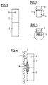
- the measuring device shown in FIGS. 1-4 has an actual measuring unit 1 and a battery compartment 2 connected to it.
- the housing of parts 1 and 2 has a cylindrical shape with an extension 3 as a radiator sensor.
- the measuring unit 1 has a removable or hinged cover 4, which protects a socket 5 for connecting a reading device described below.
- a temperature sensor 6 for detecting the room temperature is located on the front of the measuring unit 1.
- the measuring device 1, 2 is fastened according to FIG. 4 by means of a holder 8 which is glued and sealed to a heating element 7 in such a way that it cannot be removed or even its position changed by unauthorized persons.
- each radiator for example an apartment, an office or any consumer, is now provided with a device according to FIGS. 1-4.
- the measuring units 1 are equipped with a microprocessor that is continuous is powered by the batteries in the battery compartment 2. It is programmed so that, based on the temperature difference between the detected surface temperature of the radiator at the attachment point and an assumed reference room temperature of, for example, 20 ° C, it calculates heat output by the radiator. This consumption is recorded, for example, every four minutes and added up in a meter in such a way that after a certain acquisition time, for example after a month or a quarter, the meter reading corresponds to the energy given off by the radiator.
- the measuring unit is only activated from a certain detected surface temperature of the radiator, for example 31 ° C., or else a certain difference between the surface temperature of the radiator and the room temperature detected by the sensor 6, for example 2-4 ° C.
- a reading and display device In order to read out the values added up in the measuring unit 1 over a certain period of time, a reading and display device according to FIG. 5 is provided.
- This device 9 has a plug 10, which can be inserted into the socket 5 of each measuring unit 1, and it is provided with a six-digit LCD display 11, for example.
- the device 9 also has a temperature sensor 12, by means of which the room temperature can be detected and displayed on the display 11.
- the device 9 is also equipped with a microprocessor.
- the device 9 for reading out the counter reading from a specific measuring unit 1 according to FIG. 6 is plugged onto the same, thereby activating the transmission of data from the measuring unit 1 into the device 9 and the data are stored in the device 9.
- both the counter reading of the measuring unit 1 and a code which designates this unit or the heating element to which it is attached are transferred to a memory of the reading device 9.
- the meter reading read out is displayed by the display 11, so that the consumer, for example the tenant, can immediately take note of this meter reading. If the reading device 9 is connected to the same measuring unit 1 again at a later time, the assigned code remains stored and the corresponding memory of the device 9 records the new counter reading.
- the microprocessor of the reading device 9 is programmed in such a way that it checks whether all measuring units 1 have been correctly read out.
- the sum of the individual meter readings can itself be formed in the measuring device 9 and this sum can be transmitted to the clearing house, at which there is no longer any need to check for correctness.
- the reading device 9 can preferably be plugged into a wall holder 13 when not in use and thereby display the room temperature detected by the sensor 6.
- a battery which feeds the device 9 can be accommodated in the holder 13.
- This device therefore does not need to contain a battery, since in the operating state according to FIG. when reading out data from the measuring units 1, from these measuring units or their battery, can be fed, while when used as a thermometer according to FIG. 7 it can be fed by the batteries of the holder 13.
- This device can therefore be made particularly small, so that it can be sent to the clearing house as a data carrier.
- a cable can be provided, which is either permanently or pluggably connected to the reading device and can be provided with a plug for connection to the measuring units 1. This makes it even easier to mount measuring units in hard-to-reach places where the reader 9 could no longer be plugged on.
- a further safeguard against any possibility of fraud can be that the programming of both the measuring unit 1 and the reading device 9 takes place via a separable connection, which can only be created again after a seal has been broken open in order to reconnect one or the other part of the device program.
- the equipment described is particularly suitable for retrofitting existing heating systems, since there is only the problem of expediently attaching the measuring unit 1 to any existing radiator and detecting the surface temperature.
- the temperature sensor 3 is firmly attached to the measuring unit 1.
- it could also be arranged to be adjustable, or a temperature sensor could be provided which is movably connected to the measuring unit via a cable, so that it can be correctly attached to a suitable location of a radiator even in extreme cases.
- the meter reading is arbitrary Measuring units can be displayed at any time by plugging the reader 9 in order to check the consumption at any time. In this case, of course, the meter reading must not be reset in the measuring unit. However, it is also possible to allow reading out of the counter readings only on a key date or in a stub period to be determined and in this case to reset the counter of the measuring unit 1 to zero after each reading out of a counter reading.
- a time code can also be stored, from which the time of reading can be determined at each point of use. Since each measuring unit has to have a time base, preferably a quartz-controlled clock generator, in order to control the periodic measurement value acquisition, the provision and reading out of a time code is not associated with any considerable additional outlay.
- the reliability of the measurement naturally also depends on a reliable power supply for the measuring units.
- the battery compartment can be sealed in order to avoid or detect any unauthorized manipulation of the batteries.
- solar cells can be provided which support or take over the power supply entirely. In this context, it would also be possible to use the remaining data to provide and read out data about the operating state of the measuring unit, for example about the state of charge of the battery.
Abstract
Description
Die vorliegende Erfindung betrifft ein Verfahren und eine Gerätschaft zur Verbrauchsermittlung mehrerer Verbraucher mit je mehreren Verbrauchsstellen und/oder Verbrauchsarten, gemäss Oberbegriff des Anspruchs 1 bzw. des Anspruchs 5. Die DE-A-34 35 224 betrifft ein Verfahren und eine Gerätschaft dieser Art. Das Auslesen der Zählerstände mittels des Lesegerätes muss hierbei durch eine befugte Person erfolgen oder per Funk übermittelt werden, was mit verschiedenen Nachteilen verbunden ist. Trotz des erheblichen Aufwandes an Arbeitszeit und der Notwendigkeit, der befugten Person Zutritt zu allen Wohnungen zu verschaffen, in welchen die Zählerstände an verschiedenen Heizkörpern abzulesen sind, bzw. des Aufwandes an Uebermittlungsgeräten, besteht keine Gewähr dafür, dass die Ablesung vollständig und korrekt erfolgt.The present invention relates to a method and a device for determining the consumption of several consumers, each with several points of consumption and / or types of consumption, according to the preamble of
Ziel vorliegender Erfindung ist es, die Erfassung der Verbrauchsdaten derart sicherzustellen, dass Irrtümer oder bewusste Fehlablesungen ausgeschlossen werden und dass somit das Auslesen der Daten durch den Verbraucher selbst erfolgen kann, derart, dass eine Ablesung durch eine befugte Person unnötig wird. Dieses Ziel wird insbesondere gemäss den Ansprüchen 1 bzw. 6 erreicht.The aim of the present invention is to ensure that the consumption data are recorded in such a way that errors or deliberate incorrect readings are excluded and that the data can thus be read out by the consumer himself, in such a way that reading by an authorized person is unnecessary. This goal is achieved in particular according to
Die Erfindung wird nun anhand eines in der Zeichnung dargestellten Ausführungsbeispiels der erfindungsgemässen Gerätschaft und anhand verschiedener Varianten näher erläutert.
Figur 1 zeigt eine Seitenansicht eines Messgerätes,Figur 2 zeigt eine Draufsicht auf das Messgerät,Figur 3 zeigt eine Draufsicht auf das Messgerät bei zum Auslesen von Daten geöffnetem Deckel,- Figur 4 zeigt eine schematische Seitenansicht des an einem Heizkörper angebrachten Messgerätes,
Figur 5 zeigt eine Ansicht des Lese- und Anzeigegerätes,Figur 6 zeigt das auf das Messgerät aufgesteckte Lese- und Anzeigegerät- und Figur 7 zeigt das Lese- und Anzeigegerät als Raumthermometer mit einem Halter verbunden.
- FIG. 1 shows a side view of a measuring device,
- FIG. 2 shows a top view of the measuring device,
- FIG. 3 shows a top view of the measuring device with the cover open for reading out data,
- FIG. 4 shows a schematic side view of the measuring device attached to a radiator,
- FIG. 5 shows a view of the reading and display device,
- FIG. 6 shows the reading and display device plugged onto the measuring device
- and FIG. 7 shows the reading and display device connected to a holder as a room thermometer.
Das in den Figuren 1 - 4 dargestellte Messgerät weist eine eigentliche Messeinheit 1 und ein damit verbundenes Batteriefach 2 auf. Gemäss den Figuren 2 und 3 weist das Gehäuse der Teile 1 und 2 zylindrische Form auf mit einem Fortsatz 3 als Heizkörpersensor. An der Oberseite weist die Messeinheit 1 einen wegnehmbaren oder aufklappbaren Deckel 4 auf, der eine Steckbuchse 5 zum Anschluss eines unten beschriebenen Lesegerätes schützt. An der Vorderseite der Messeinheit 1 befindet sich ein Temperaturfühler 6 zur Erfassung der Raumtemperatur.The measuring device shown in FIGS. 1-4 has an
Das Messgerät 1,2 wird gemäss Figur 4 mittels eines an einem Heizkörper 7 festgeklebten und plombierten Halters 8 derart befestigt, dass es durch Unbefugte nicht entfernt oder auch nur in seiner Lage verändert werden kann.The
Zur Erfassung der insgesamt bezogenen Heizenergie, bzw. zur Erstellung einer individuellen Heizkostenabrechnung, wird nun jeder Heizkörper beispielsweise einer Wohnung, eines Büros oder irgendeines Verbrauchers, mit einem Gerät gemäss Figuren 1 - 4 versehen. Die Messeinheiten 1 sind mit einem Mikroprozessor bestückt, der dauernd durch die im Batteriefach 2 vorhandenen Batterien gespeist wird. Er ist so programmiert, dass er gestützt auf die Temperaturdifferenz zwischen der erfassten Oberflächentemperatur des Heizkörpers an der Befestigungsstelle und einer angenommenen Bezugs-Raumtemperatur von beispielsweise 20 °C eine Wärmeabgabe durch den Heizkörper errechnet. Dieser Verbrauch wird beispielsweise alle vier Minuten erfasst und in einem Zähler aufaddiert, derart, dass nach einer bestimmten Erfassungszeit, beispielsweise nach einem Monat oder einem Vierteljahr, der Zählerstand der durch den Heizkörper abgegebenen Energie entspricht. Es werden dann alle Zählerstände eines bestimmten Verbrauchers, also beispielsweise aus einer bestimmten Wohnung addiert, um den Gesamtverbrauch zu ermitteln und eine Abrechnung zu erstellen. Dabei ist vorgesehen, die Messeinheit erst ab einer bestimmten erfassten Oberflächentemperatur des Heizkörpers, beispielsweise 31 °C oder aber einer bestimmten Differenz zwischen der Oberflächentemperatur des Heizkörpers und der durch den Fühler 6 erfassten Raumtemperatur von beispielsweise 2 - 4 °C zu aktivieren.To record the total heating energy used, or to create an individual heating bill, each radiator, for example an apartment, an office or any consumer, is now provided with a device according to FIGS. 1-4. The
Um die in der Messeinheit 1 in einem bestimmten Zeitraum aufaddierten Werte auszulesen, ist ein Lese- und Anzeigegerät gemäss Figur 5 vorgesehen. Dieses Gerät 9 weist einen Stecker 10 auf, der in die Buchse 5 jeder Messeinheit 1 eingeführt werden kann, und es ist mit einer beispielsweise sechsstelligen LCD-Anzeige 11 versehen. Das Gerät 9 weist ferner einen Temperatursensor 12 auf, mittels dem die Raumtemperatur erfasst und auf der Anzeige 11 angezeigt werden kann. Das Gerät 9 ist ebenfalls mit einem Mikroprozessor ausgerüstet.In order to read out the values added up in the
Wie erwähnt, wird das Gerät 9 zum Auslesen des Zählerstandes aus einer bestimmten Messeinheit 1 gemäss Figur 6 auf dieselbe aufgesteckt, womit die Uebertragung von Daten aus der Messeinheit 1 in das Gerät 9 aktiviert wird und die Daten im Gerät 9 abgespeichert werden. Dabei wird beispielsweise sowohl der Zählerstand der Messeinheit 1 als auch ein Code, welcher diese Einheit bzw. den Heizkörper, an welchem sie angebracht ist, bezeichnet, in einen Speicher des Lesegerätes 9 übertragen. Zugleich wird der ausgelesene Zählerstand durch die Anzeige 11 angezeigt, so dass der Verbraucher, beispielsweise der Wohnungsmieter, diesen Zählerstand sogleich zur Kenntnis nehmen kann. Wird in einem späteren Zeitpunkt das Lesegerät 9 wieder mit derselben Messeinheit 1 verbunden, bleibt der zugeordnete Code gespeichert und der entsprechende Speicher des Gerätes 9 nimmt den neuen Zählerstand auf. An einem bestimmten Stichtag sind nun alle vorhandenen Messeinheiten 1 in der soeben beschriebenen Weise auszulesen. Im Gerät 9 sind dann die Zählerstände aller vorhandenen Messeinheiten 1 mit den zugeordneten Codes abgespeichert. Diese abgespeicherten Daten müssen nun vollständig an eine Verrechnungstelle mit einem zentralen Rechner übermittelt werden, entweder indem das Gerät 9 an die Verrechnungsstelle eingesandt wird, wo die Daten ausgelesen werden, indem ein Datenträger aus dem Gerät 9 entnommen und eingesandt wird oder indem die abgespeicherten Daten über ein entsprechendes Modem und die Telefonleitung an die Verrechnungsstelle übermittelt werden. An der Verrechnungstelle werden die eingegangen Daten vorerst auf ihre Richtigkeit überprüft, d.h. es wird festgestellt, ob für alle bei einem bestimmten Verbraucher installierten Messeinheiten der entsprechende Code sowie ein Zählerstand vorliege. Wenn dies nicht der Fall ist, muss die Ablesung wiederholt und dann erneut überprüft und ausgewertet werden. Zur Auswertung erfolgt eine Addition aller Zählerstände.As mentioned, the
Es bestehen allerdings auch andere Möglichkeiten zur Absicherung gegen Irrtum oder Betrug. Es kann beispielsweise sein, dass der Mikroprozessor des Lesegerätes 9 derart programmiert ist, dass er überprüft, ob alle Messeinheiten 1 korrekt ausgelesen worden sind. In diesem Falle kann im Messgerät 9 selbst die Summe der einzelnen Zählerstände gebildet und diese Summe an die Verrechnungsstelle übermittelt werden, an welcher keine Ueberprüfung auf Richtigkeit mehr zu erfolgen braucht.However, there are other ways to guard against errors or fraud. For example, the microprocessor of the
Gemäss Figur 7 kann das Lesegerät 9 bei Nichtgebrauch vorzugsweise in einen Wandhalter 13 gesteckt werden und dabei die durch den Fühler 6 erfasste Raumtemperatur anzeigen. Im Halter 13 kann eine Batterie untergebracht sein, welche das Gerät 9 speist. Dieses Gerät braucht somit keine Batterie zu enthalten, da es beim Betriebszustand gemäss Figur 6, d.h. beim Auslesen von Daten aus den Messeinheiten 1, aus diesen Messeinheiten bzw. deren Batterie, gespeist werden kann, während es bei Verwendung als Thermometer gemäss Figur 7 durch die Batterien des Halters 13 gespeist werden kann. Dieses Gerät kann somit besonders klein ausgeführt werden, sodass es als Datenträger an die Verrechnungsstelle eingesandt werden kann.According to FIG. 7, the
Es sind verschiedene Ausführungsvarianten möglich. Es kann beispielsweise ein Kabel vorgesehen sein, das entweder fest oder steckbar mit dem Lesegerät verbunden ist und mit einem Stecker zur Verbindung mit den Messeinheiten 1 versehen sein kann. Damit wird es noch leichter möglich, Messeinheiten an schwer zugänglichen Stellen anzubringen, an welchen das Lesegerät 9 nicht mehr aufgesteckt werden könnte.Different versions are possible. For example, a cable can be provided, which is either permanently or pluggably connected to the reading device and can be provided with a plug for connection to the
Das obenstehende Ausführungsbeispiel ist ausschliesslich bezüglich der Erfassung der konsumierten Heizenergie, bzw. einer individuellen Heizkostenabrechnung beschrieben worden. Der eingangs erwähnte Missstand, wonach befugte Personen Verbrauchszähler, beispielsweise Elektrizitäts,- Wasserzähler oder Gaszähler abzulesen haben, könnte gemäss dem erfindungsgemässen Verfahren, bzw. mit Hilfe der erfindungsgemässen Gerätschaft, auch behoben werden. Es bedarf keiner näheren Erläuterung darüber, dass mit Hilfe des Lesegerätes 9 auch andere Zählerstände ausgelesen werden könnten, sofern dieselben nur in geeigneter lesbarer Form vorliegen. Es wäre dabei selbst möglich, für einen bestimmten Verbraucher alle Zählerstände mit ein und demselben Gerät abzulesen, wobei jedem Zählerstand in oben beschriebener Weise ein Code zugeordnet ist, welcher den einzelnen Zähler bezeichnet. An einer zentralen Verrechnungstelle könnte dann festgestellt werden, wie hoch der Verbrauch der einzelnen Energien Wasser oder dergleichen war, und es könnte eine generelle Kostenabrechnung erstellt werden.The above exemplary embodiment has been described exclusively with regard to the recording of the heating energy consumed or an individual heating bill. The above-mentioned grievance, according to which authorized persons can read consumption meters, for example electricity, water or gas meters could also be remedied according to the method according to the invention or with the aid of the equipment according to the invention. There is no need for a more detailed explanation that other counter readings could also be read out with the aid of the
Eine weitere Absicherung gegen jede Betrugsmöglichkeit kann darin bestehen, dass die Programmierung sowohl der Messeinheit 1 als auch des Lesegerätes 9 über eine trennbare Verbindung erfolgt, die nur nach dem Aufbrechen einer Plombierung wieder erstellt werden kann, um den einen oder anderen Teil der Gerätschaft neu zu programmieren.A further safeguard against any possibility of fraud can be that the programming of both the measuring
Die beschriebene Gerätschaft eignet sich ganz besonders zur Nachrüstung bestehender Heizsysteme, indem lediglich das Problem besteht, die Messeinheit 1 zweckmässig an einem beliebigen bestehenden Heizkörper anzubringen und die Oberflächentemperatur zu erfassen. Beim Ausführungsbeispiel ist angenommen, der Temperatursensor 3 sei fest an der Messeinheit 1 angebracht. Er könnte allerdings auch verstellbar angeordnet sein oder aber es könnte ein über ein Kabel beweglich mit der Messeinheit verbundener Temperatursensor vorgesehen sein, damit er auch in extremen Fällen korrekt an einer geeigneten Stelle eines Heizkörpers angebracht werden kann.The equipment described is particularly suitable for retrofitting existing heating systems, since there is only the problem of expediently attaching the
Es ist oben erwähnt worden, dass der Zählerstand beliebiger Messeinheiten zu beliebigen Zeiten durch Aufstekken des Lesegerätes 9 angezeigt werden kann, um den Verbrauch in einem beliebigen Zeitpunkt zu überprüfen. In diesem Falle darf natürlich keine Rückstellung des Zählerstandes in der Messeinheit erfolgen. Es ist jedoch auch möglich, ein Auslesen der Zählerstände nur an einem Stichtag oder in einer zu bestimmenden Stichperiode zu erlauben und in diesem Falle nach jedem Auslesen eines Zählerstandes den Zähler der Messeinheit 1 auf Null zurückzustellen.It has been mentioned above that the meter reading is arbitrary Measuring units can be displayed at any time by plugging the
Zur weiteren Sicherstellung bzw. Ueberprüfung der Korrektheit der Ablesung kann ausser den oben erwähnten Daten auch ein Zeitcode gespeichert werden, aus dem der Zeitpunkt der Ablesung an jeder Verbrauchsstelle ermittelt werden kann. Da jede Messeinheit ohnehin eine Zeitbasis, vorzugsweise einen quarzgesteuerten Taktgeber, aufweisen muss, um die periodische Messwerterfassung zu steuern, ist mit der Bereitstellung und dem Auslesen eines Zeitcodes kein erheblicher zusätzlicher Aufwand verbunden.To further ensure or check the correctness of the reading, in addition to the data mentioned above, a time code can also be stored, from which the time of reading can be determined at each point of use. Since each measuring unit has to have a time base, preferably a quartz-controlled clock generator, in order to control the periodic measurement value acquisition, the provision and reading out of a time code is not associated with any considerable additional outlay.
Die Zuverlässigkeit der Messung hängt natürlich auch von einer zuverlässigen Stromversorgung der Messeinheiten ab. Einerseits kann das Batteriefach plombiert sein, um jede unbefugte Manipulation an den Batterien zu vermeiden bzw. feststellen zu können. Andererseits können Solarzellen vorgesehen sein, welche die Stromversorgung unterstützen oder ganz übernehmen. Es wäre in diesem Zusammenhang auch möglich, mit den übrigen Daten jeweils Daten über den Betriebszustand der Messeinheit bereitzustellen und auszulesen, beispielsweise über den Ladezustand der Batterie.The reliability of the measurement naturally also depends on a reliable power supply for the measuring units. On the one hand, the battery compartment can be sealed in order to avoid or detect any unauthorized manipulation of the batteries. On the other hand, solar cells can be provided which support or take over the power supply entirely. In this context, it would also be possible to use the remaining data to provide and read out data about the operating state of the measuring unit, for example about the state of charge of the battery.
Claims (11)
- A method for the determination of the consumption of a plurality of consumers having each a plurality of consumer's installations and/or kinds of consumption, a counter being associated to each installation and/or mode of consumption of each consumer, and the count of all counters of each consumer being read out by successively connecting a reading device to each of the counters, the data referring to the consumption determined in this manner being transmitted to a central processing center where they are evaluated, characterised in that the counts of the counters of each consumer are read out by means of a reading device (9) which is associated to said consumer, whereby the consumption is stored in said associated reading device (9), the counters and the reading device being interlocked in such a manner that a valid result is only provided if a consumer has read out each associated counter once.
- Method according to claim 1, characterised in that said reading device or a storage medium which is used therewith is transmitted to said processing center.
- Method according to claim 1 or 2, characterised in that consumptions of different kinds, e.g. of heating or hot water, gas, electricity, are counted according to different rates and determined by one and the same reading device.
- Method according to any one of claims 1 to 3, characterised in that a designating code is associated to each consumer's installation, and in that each code and the count of its associated counter are separately read out, stored, and transmitted to said processing center, whereupon the data are checked for completeness and the total consumption is determined.
- Equipment for the determination of the consumption of a consumer having a plurality of consumer's installations and/or kinds of consumption, each installation having an associated counter to which a reading device (9) can be connected in order to read out its count, characterised in that said counters and said reading device (9) are programmed in such a manner that a value which qualifies as correct is stored in said reading device (8) only if the count of all counters has been recorded and summed up.
- Equipment according to claim 5, characterised in that each counter is designated by a code which is read out when said reading device is connected, said reading device storing a "correct" information if the code of each counter has been read out once.
- Equipment, substantially according to claim 5, characterised in that said reading device is provided with respective memories for a code and a count of each installation resp. kind of consumption, and in that a computer is provided in said processing center which is capable of verifying the completeness and accuracy of the codes and the associated counter counts stored in said memories and of summing them up as confirmed counter counts.
- Equipment, particularly according to one of claims 5 to 7, characterised in that said counters are capable of being programmed by a disruptable connection.
- Equipment, particularly according to one of claims 5 to 8, characterised in that the counters are designed for a periodical detection of measures, e.g. at intervals of 4 min.
- Equipment, particularly according to one of claims 7 to 9, characterised in that the counters have a respective sensor for the detection of a radiator or heating water temperature and of an ambient temperature and are switched on when a certain temperature difference or a certain speed of the temperature rise is exceeded.
- Equipment according to any one of claims 5 to 10, characterised in that a stationary holder having a power supply is provided for said reading device, and in that said reading device has a display for the room temperature.
Applications Claiming Priority (2)
| Application Number | Priority Date | Filing Date | Title |
|---|---|---|---|
| CH482/91 | 1991-02-15 | ||
| CH482/91A CH682696A5 (en) | 1991-02-15 | 1991-02-15 | A method and equipment for determining consumption. |
Publications (2)
| Publication Number | Publication Date |
|---|---|
| EP0499583A1 EP0499583A1 (en) | 1992-08-19 |
| EP0499583B1 true EP0499583B1 (en) | 1995-11-02 |
Family
ID=4188014
Family Applications (1)
| Application Number | Title | Priority Date | Filing Date |
|---|---|---|---|
| EP92810081A Expired - Lifetime EP0499583B1 (en) | 1991-02-15 | 1992-02-06 | Method and device for consumption determination |
Country Status (10)
| Country | Link |
|---|---|
| EP (1) | EP0499583B1 (en) |
| JP (1) | JPH0599702A (en) |
| AT (1) | ATE129808T1 (en) |
| CH (1) | CH682696A5 (en) |
| CZ (1) | CZ286093B6 (en) |
| DE (1) | DE59204160D1 (en) |
| DK (1) | DK0499583T3 (en) |
| HU (1) | HU213969B (en) |
| PL (1) | PL170264B1 (en) |
| SK (1) | SK280792B6 (en) |
Families Citing this family (2)
| Publication number | Priority date | Publication date | Assignee | Title |
|---|---|---|---|---|
| EP0616201A1 (en) * | 1993-03-19 | 1994-09-21 | Landis & Gyr Business Support AG | Housing for a heat meter |
| SK69898A3 (en) * | 1997-06-13 | 2000-05-16 | Bernina Electronic Ag | Method and device for measuring a consumption |
Family Cites Families (5)
| Publication number | Priority date | Publication date | Assignee | Title |
|---|---|---|---|---|
| DK149010C (en) * | 1980-10-16 | 1986-05-26 | Iss Clorius Int As | PLANT FOR SPECIFIC REGISTRATION OF HEAT CONSUMPTION FOR A NUMBER OF PRODUCTIVE ELEMENTS, SUCH AS RADIATORS |
| DE3435224A1 (en) * | 1984-09-26 | 1986-04-03 | Brown, Boveri & Cie Ag, 6800 Mannheim | Electronic heating measurement method |
| DE3514412A1 (en) * | 1985-04-20 | 1986-10-23 | Compmess Datentechnik und Mess GmbH, 7900 Ulm | Method for separately detecting the consumption of thermal energy of a plurality of consumer units fed from an energy control centre |
| DE3535869A1 (en) * | 1985-10-08 | 1987-04-09 | Sht Software Hardwaretechnik G | Electronic device for calculating heating costs |
| DE8813323U1 (en) * | 1988-10-22 | 1988-12-15 | Kalorimeta Ag & Co, 2000 Hamburg, De |
-
1991
- 1991-02-15 CH CH482/91A patent/CH682696A5/en not_active IP Right Cessation
-
1992
- 1992-02-06 DE DE59204160T patent/DE59204160D1/en not_active Expired - Fee Related
- 1992-02-06 EP EP92810081A patent/EP0499583B1/en not_active Expired - Lifetime
- 1992-02-06 DK DK92810081.7T patent/DK0499583T3/en active
- 1992-02-06 AT AT92810081T patent/ATE129808T1/en not_active IP Right Cessation
- 1992-02-12 CZ CS1992424A patent/CZ286093B6/en not_active IP Right Cessation
- 1992-02-12 SK SK424-92A patent/SK280792B6/en unknown
- 1992-02-13 PL PL92293466A patent/PL170264B1/en unknown
- 1992-02-14 HU HU9200453A patent/HU213969B/en not_active IP Right Cessation
- 1992-02-14 JP JP4028302A patent/JPH0599702A/en active Pending
Also Published As
| Publication number | Publication date |
|---|---|
| HUT66922A (en) | 1995-01-30 |
| EP0499583A1 (en) | 1992-08-19 |
| ATE129808T1 (en) | 1995-11-15 |
| HU9200453D0 (en) | 1992-04-28 |
| PL170264B1 (en) | 1996-11-29 |
| DK0499583T3 (en) | 1995-12-04 |
| JPH0599702A (en) | 1993-04-23 |
| CS42492A3 (en) | 1992-10-14 |
| CZ286093B6 (en) | 2000-01-12 |
| SK280792B6 (en) | 2000-07-11 |
| DE59204160D1 (en) | 1995-12-07 |
| CH682696A5 (en) | 1993-10-29 |
| HU213969B (en) | 1997-11-28 |
| PL293466A1 (en) | 1992-11-16 |
Similar Documents
| Publication | Publication Date | Title |
|---|---|---|
| DE3612121C2 (en) | System for recording and controlling the services of utilities to end users via a data transmission network | |
| WO1994009464A1 (en) | Installation for reading the consumption figures for various consumption quantities in a building | |
| EP0407902B1 (en) | Consumption indication device for supply means | |
| DE112008003940T5 (en) | Prepayment system for the supply of water or gas using a wireless smart card and counters for the system | |
| DE3813498A1 (en) | System for telemetering (remote metering) the electric power consumption of different loads (consumers) | |
| DE10054771A1 (en) | Fastening and contact device for a private household electronic electricity meter that can be readily mounted and dismounted without need for interrupting customer electricity supply | |
| EP0015407B1 (en) | Device to measure electrically the heat consumption of individual radiators | |
| EP1843136A2 (en) | Method and system for determining and/or displaying heating costs | |
| EP0499583B1 (en) | Method and device for consumption determination | |
| EP0602676A2 (en) | Electrical power distribution system | |
| DE102007021138A1 (en) | Mounting system comprises mounting element which has information unit with non volatile memory for storage of mounting element or collection point identifying information and data | |
| DE19547281A1 (en) | Measurement system with interchangeable sensor modules for scientific and technical instrumentation | |
| DE69631798T2 (en) | CALORIMETER PROCESS AND DEVICE FOR RADIATOR | |
| EP0495189B1 (en) | Method and installation for assuring and determining the guarantee time of an apparatus | |
| DE19832825C2 (en) | Process for computer-aided operation of devices for irradiation of the human body | |
| DE3730529A1 (en) | Method of measuring the dimension index, defined by the ratio of desired utilisation to actual utilisation, of a heating unit of a heating installation | |
| DE19821536B4 (en) | Method for electronically measuring the amount of heat emitted by a radiator | |
| DE3050923C2 (en) | ||
| DE102015108436B4 (en) | Analysis device for analyzing nutrient values in liquid media | |
| DE4008859A1 (en) | Reader for magnetic cards for access controller - has programmable memory, power and data output and real=time measurement circuit integrated into unit | |
| DE19638614A1 (en) | Electricity consumption counter | |
| DE3044262A1 (en) | Thermal consumption measurement unit - provides display when required using periodic or requested storage for plug-in display | |
| DE102010052104A1 (en) | Heat meter for use in district heating plant for built in domestic supply line for determining consumed heat quantity, has temperature sensor switched on so that temperature in return line of primary circuit is involved in evaluation | |
| DE3603294A1 (en) | Method and device for measuring the quantity of energy fed to one or more energy-dissipating devices | |
| DE2944660A1 (en) | ELECTRICITY METER FOR PERIODIC APPLICATION OF DIFFERENT TARIFFS |
Legal Events
| Date | Code | Title | Description |
|---|---|---|---|
| PUAI | Public reference made under article 153(3) epc to a published international application that has entered the european phase |
Free format text: ORIGINAL CODE: 0009012 |
|
| 17P | Request for examination filed |
Effective date: 19920520 |
|
| AK | Designated contracting states |
Kind code of ref document: A1 Designated state(s): AT CH DE DK FR LI |
|
| 17Q | First examination report despatched |
Effective date: 19940916 |
|
| GRAA | (expected) grant |
Free format text: ORIGINAL CODE: 0009210 |
|
| AK | Designated contracting states |
Kind code of ref document: B1 Designated state(s): AT CH DE DK FR LI |
|
| REF | Corresponds to: |
Ref document number: 129808 Country of ref document: AT Date of ref document: 19951115 Kind code of ref document: T |
|
| REG | Reference to a national code |
Ref country code: DK Ref legal event code: T3 |
|
| REF | Corresponds to: |
Ref document number: 59204160 Country of ref document: DE Date of ref document: 19951207 |
|
| REG | Reference to a national code |
Ref country code: CH Ref legal event code: NV Representative=s name: AMMANN PATENTANWAELTE AG BERN |
|
| ET | Fr: translation filed | ||
| PLBE | No opposition filed within time limit |
Free format text: ORIGINAL CODE: 0009261 |
|
| STAA | Information on the status of an ep patent application or granted ep patent |
Free format text: STATUS: NO OPPOSITION FILED WITHIN TIME LIMIT |
|
| 26N | No opposition filed | ||
| PGFP | Annual fee paid to national office [announced via postgrant information from national office to epo] |
Ref country code: CH Payment date: 20010227 Year of fee payment: 10 |
|
| PGFP | Annual fee paid to national office [announced via postgrant information from national office to epo] |
Ref country code: DE Payment date: 20010427 Year of fee payment: 10 |
|
| PGFP | Annual fee paid to national office [announced via postgrant information from national office to epo] |
Ref country code: DK Payment date: 20020225 Year of fee payment: 11 |
|
| PGFP | Annual fee paid to national office [announced via postgrant information from national office to epo] |
Ref country code: FR Payment date: 20020227 Year of fee payment: 11 |
|
| PG25 | Lapsed in a contracting state [announced via postgrant information from national office to epo] |
Ref country code: LI Free format text: LAPSE BECAUSE OF NON-PAYMENT OF DUE FEES Effective date: 20020228 Ref country code: CH Free format text: LAPSE BECAUSE OF NON-PAYMENT OF DUE FEES Effective date: 20020228 |
|
| PGFP | Annual fee paid to national office [announced via postgrant information from national office to epo] |
Ref country code: AT Payment date: 20020228 Year of fee payment: 11 |
|
| PG25 | Lapsed in a contracting state [announced via postgrant information from national office to epo] |
Ref country code: DE Free format text: LAPSE BECAUSE OF NON-PAYMENT OF DUE FEES Effective date: 20020903 |
|
| REG | Reference to a national code |
Ref country code: CH Ref legal event code: PL |
|
| PG25 | Lapsed in a contracting state [announced via postgrant information from national office to epo] |
Ref country code: AT Free format text: LAPSE BECAUSE OF NON-PAYMENT OF DUE FEES Effective date: 20030206 |
|
| PG25 | Lapsed in a contracting state [announced via postgrant information from national office to epo] |
Ref country code: DK Free format text: LAPSE BECAUSE OF NON-PAYMENT OF DUE FEES Effective date: 20030228 |
|
| REG | Reference to a national code |
Ref country code: DK Ref legal event code: EBP |
|
| PG25 | Lapsed in a contracting state [announced via postgrant information from national office to epo] |
Ref country code: FR Free format text: LAPSE BECAUSE OF NON-PAYMENT OF DUE FEES Effective date: 20031031 |
|
| REG | Reference to a national code |
Ref country code: FR Ref legal event code: ST |