EP0499138A2 - Zusammenbau um Spannungsimpulsversorgung in einem elektrostatischen Abscheider zu steuern - Google Patents
Zusammenbau um Spannungsimpulsversorgung in einem elektrostatischen Abscheider zu steuern Download PDFInfo
- Publication number
- EP0499138A2 EP0499138A2 EP92101961A EP92101961A EP0499138A2 EP 0499138 A2 EP0499138 A2 EP 0499138A2 EP 92101961 A EP92101961 A EP 92101961A EP 92101961 A EP92101961 A EP 92101961A EP 0499138 A2 EP0499138 A2 EP 0499138A2
- Authority
- EP
- European Patent Office
- Prior art keywords
- voltage
- direct voltage
- base
- generator
- value
- Prior art date
- Legal status (The legal status is an assumption and is not a legal conclusion. Google has not performed a legal analysis and makes no representation as to the accuracy of the status listed.)
- Granted
Links
Images



Classifications
-
- B—PERFORMING OPERATIONS; TRANSPORTING
- B03—SEPARATION OF SOLID MATERIALS USING LIQUIDS OR USING PNEUMATIC TABLES OR JIGS; MAGNETIC OR ELECTROSTATIC SEPARATION OF SOLID MATERIALS FROM SOLID MATERIALS OR FLUIDS; SEPARATION BY HIGH-VOLTAGE ELECTRIC FIELDS
- B03C—MAGNETIC OR ELECTROSTATIC SEPARATION OF SOLID MATERIALS FROM SOLID MATERIALS OR FLUIDS; SEPARATION BY HIGH-VOLTAGE ELECTRIC FIELDS
- B03C3/00—Separating dispersed particles from gases or vapour, e.g. air, by electrostatic effect
- B03C3/34—Constructional details or accessories or operation thereof
- B03C3/66—Applications of electricity supply techniques
- B03C3/68—Control systems therefor
Definitions
- This present invention relates to an assembly for controlling a voltage pulse feeder in an electrostatic precipitator, in particular in an electrostatic precipitator in a coal combustion plant and, anyway, in a plant wherein particles are to be collected which have an high resistivity, from 108 ⁇ . cm and over.
- the prior art comprises in said precipitators voltage pulse feeders (which will be referred to only as - feeder(s) - in the following description) by means of which the insulated electrode is given a negative polarity direct voltage of some tens of kV, to which direct voltage, voltage pulses are added which range from tens to hundreds of microseconds ( ⁇ s) with a convenient frequency and peak values of some tens of kV (said negative polarity direct voltage will be referred to only as - base direct voltage - in the following description).
- the voltage pulses having short life and proper voltage give the ash particles in the smokes remarkable electric charges so that the electric field generated by the base direct voltage works to collect the particles by electrostatic action.
- the prior art comprises feeders made according to two different assemblies :
- the peculiarity of both said assemblies is to afford manually or automatically an independent control of the base direct voltage and voltage pulse amplitude.
- a drawback in the prior art is that the efficiency in collecting the solid particles is much jeopardized by unsteadyness of said voltages and, particularly after a discharge in a precipitator, is jeopardized on resetting the base direct voltage and the amplitude of the voltage pulses.
- the base direct voltage and the pulse voltage added thereto are interdependent in other words, when one of said voltages rises the other lows, and vice versa.
- the object of this invention is to obviate the low efficiency caused by said interdependency between said voltages in the assemblies according to the prior art.
- the invention as characterized in the claims, provides an assembly which automatically keeps steady the base direct voltage on varying the pulse amplitudes added thereto and, similarly, automatically keeps steady the auxiliary direct voltage in order to generate the pulse on varying the base direct voltage.
- This assembly works to generate the base current voltage and/or the pulse voltage irrespective of the control being manual or automatic.
- Fig. 1 shows an assembly comprising: a feeder 1 comprising a base direct voltage generator 2; an auxiliary direct voltage generator 3 which generates voltage pulses; a precipitator 4 comprising an insulated filiform sender electrode 5, and a collecting electrode 6 for collecting solid particles; a couple of electronic controllers 7A, 7B made by the firm SIATEM in Padova (Italy) with components type L141 and ⁇ A747, respectively adapted to control automatically the base direct voltage and the auxiliary direct voltage for generating pulses and to balance for both voltages all the variations caused by said interdependency; a voltage divider 8 which shows continuously the value of the base direct voltage; a voltage divider 9 which shows continuously the value of the direct voltage associated with the voltage pulses; a voltage divider 10 which shows continuously the value of total voltage on the precipitator 4; wires 11A, 11B; 12A, 12B respectively connecting said generators with said electronic controllers 7A, 7B; wires 13A, 13B respectively connecting said generators with the voltage dividers 8, 9 and said
- the collecting highest efficiency in the electrostatic precipitator is obtained by setting and keeping steady a predetermined value of the base direct voltage selected depending on the amount and quality of the solid particles in the precipitator; to the base direct voltage a collecting voltage pulse is added whose amplitude is increased gradually until a discharge occurs in the precipitator.
- Said collecting voltage pulse shall be of low frequency, from 1 Hz to 50 Hz.
- the base direct voltage and the pulse voltage are drawn to zero by the control assembly and, after a predetermined time period of some tens of milliseconds, the base direct voltage rapidly returns to the predetermined value, while the pulse voltage rapidly returns to that value which caused the discharge, reduced by a predetermined percentage, and then it increases along a low slope until a further discharge occurs in the precipitator.
- Fig. 2 shows an assembly comprising:
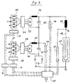
- Fig. 3 shows an assembly comprising
- Fig. 4 is a diagram of an electronic controller which may be used for automatically keeping steady, in the illustrated case, the base direct voltage for the feeder as illustrated in Figures 1, 2 and 3.
- a similar electronic controller is used for automatically keeping steady the auxiliary direct voltage associated with the pulses.
- Said controller comprises:
Landscapes
- Engineering & Computer Science (AREA)
- Automation & Control Theory (AREA)
- Electrostatic Separation (AREA)
- Elimination Of Static Electricity (AREA)
- Printers Or Recording Devices Using Electromagnetic And Radiation Means (AREA)
- Networks Using Active Elements (AREA)
Applications Claiming Priority (2)
| Application Number | Priority Date | Filing Date | Title |
|---|---|---|---|
| ITMI910398A IT1245165B (it) | 1991-02-15 | 1991-02-15 | Sistema per controllare e regolare alimentatori ad impulsi di tensione per precipitatori elettrostatici |
| ITMI910398 | 1991-02-15 |
Publications (3)
| Publication Number | Publication Date |
|---|---|
| EP0499138A2 true EP0499138A2 (de) | 1992-08-19 |
| EP0499138A3 EP0499138A3 (en) | 1992-09-30 |
| EP0499138B1 EP0499138B1 (de) | 1995-08-09 |
Family
ID=11358599
Family Applications (1)
| Application Number | Title | Priority Date | Filing Date |
|---|---|---|---|
| EP92101961A Revoked EP0499138B1 (de) | 1991-02-15 | 1992-02-06 | Zusammenbau um Spannungsimpulsversorgung in einem elektrostatischen Abscheider zu steuern |
Country Status (7)
| Country | Link |
|---|---|
| EP (1) | EP0499138B1 (de) |
| AT (1) | ATE126100T1 (de) |
| DE (1) | DE69203876T2 (de) |
| DK (1) | DK0499138T3 (de) |
| ES (1) | ES2079086T3 (de) |
| GR (1) | GR3018054T3 (de) |
| IT (1) | IT1245165B (de) |
Cited By (5)
| Publication number | Priority date | Publication date | Assignee | Title |
|---|---|---|---|---|
| WO2007014402A1 (en) * | 2005-07-25 | 2007-02-01 | Francoi Eberhardt Du Plessis | Method of and control system for controlling electrostatic separator |
| CN103079707A (zh) * | 2010-09-03 | 2013-05-01 | 分离技术有限责任公司 | 静电分离控制系统 |
| US9393573B2 (en) | 2014-04-24 | 2016-07-19 | Separation Technologies Llc | Continuous belt for belt-type separator devices |
| US9764332B2 (en) | 2015-02-13 | 2017-09-19 | Separation Technologies Llc | Edge air nozzles for belt-type separator devices |
| US11998930B2 (en) | 2020-06-22 | 2024-06-04 | Separation Technologies Llc | Process for dry beneficiation of fine and very fine iron ore by size and electrostatic segregation |
Family Cites Families (3)
| Publication number | Priority date | Publication date | Assignee | Title |
|---|---|---|---|---|
| DE3007364A1 (de) * | 1980-02-27 | 1981-09-10 | Siemens AG, 1000 Berlin und 8000 München | Steuerung fuer ein elektrofilter |
| DE3027172A1 (de) * | 1980-07-17 | 1982-02-18 | Siemens AG, 1000 Berlin und 8000 München | Verfahren zum betrieb eines elektrofilters |
| DE3531025A1 (de) * | 1985-08-30 | 1987-03-05 | Bosch Gmbh Robert | Schaltungsanordnung zur regelung der hochspannungsversorgung eines elektrostatischen filters |
-
1991
- 1991-02-15 IT ITMI910398A patent/IT1245165B/it active IP Right Grant
-
1992
- 1992-02-06 EP EP92101961A patent/EP0499138B1/de not_active Revoked
- 1992-02-06 AT AT92101961T patent/ATE126100T1/de not_active IP Right Cessation
- 1992-02-06 DK DK92101961.8T patent/DK0499138T3/da active
- 1992-02-06 ES ES92101961T patent/ES2079086T3/es not_active Expired - Lifetime
- 1992-02-06 DE DE69203876T patent/DE69203876T2/de not_active Revoked
-
1995
- 1995-11-10 GR GR950403039T patent/GR3018054T3/el unknown
Cited By (7)
| Publication number | Priority date | Publication date | Assignee | Title |
|---|---|---|---|---|
| WO2007014402A1 (en) * | 2005-07-25 | 2007-02-01 | Francoi Eberhardt Du Plessis | Method of and control system for controlling electrostatic separator |
| AU2006272493B2 (en) * | 2005-07-25 | 2009-10-22 | Blue Cube Intellectual Property Company (Pty) Ltd | Method of and control system for controlling electrostatic separator |
| CN103079707A (zh) * | 2010-09-03 | 2013-05-01 | 分离技术有限责任公司 | 静电分离控制系统 |
| US9393573B2 (en) | 2014-04-24 | 2016-07-19 | Separation Technologies Llc | Continuous belt for belt-type separator devices |
| US10092908B2 (en) | 2014-04-24 | 2018-10-09 | Separation Technologies Llc | Continuous belt for belt-type separator devices |
| US9764332B2 (en) | 2015-02-13 | 2017-09-19 | Separation Technologies Llc | Edge air nozzles for belt-type separator devices |
| US11998930B2 (en) | 2020-06-22 | 2024-06-04 | Separation Technologies Llc | Process for dry beneficiation of fine and very fine iron ore by size and electrostatic segregation |
Also Published As
| Publication number | Publication date |
|---|---|
| DK0499138T3 (da) | 1995-12-11 |
| IT1245165B (it) | 1994-09-13 |
| GR3018054T3 (en) | 1996-02-29 |
| ATE126100T1 (de) | 1995-08-15 |
| DE69203876D1 (de) | 1995-09-14 |
| EP0499138B1 (de) | 1995-08-09 |
| ES2079086T3 (es) | 1996-01-01 |
| EP0499138A3 (en) | 1992-09-30 |
| ITMI910398A0 (it) | 1991-02-15 |
| DE69203876T2 (de) | 1996-04-04 |
| ITMI910398A1 (it) | 1992-08-15 |
Similar Documents
| Publication | Publication Date | Title |
|---|---|---|
| EP0268934B1 (de) | Verfahren und Einrichtung zur Energieversorgung eines Elektroabscheiders | |
| US3530359A (en) | Adjustable arc welding power supply system | |
| EP0055903B1 (de) | Elektrische Stromversorgung | |
| AU631627B2 (en) | Method for controlling the current pulse supply to an electrostatic precipitator | |
| EP0184922A2 (de) | Verfahren zum Steuern aussetzender Spannungsversorgung für einen elektrostatischen Staubabscheider | |
| US3641740A (en) | Pulse-operated electrostatic precipitator | |
| EP0508961A1 (de) | Hochfrequenz-Kommutationstyp geschützt durch Leistungsversorgung, insbesondere für elektrostatische Abscheider | |
| EP0044488B1 (de) | Verfahren und Einrichtung zum Betrieb eines Elektrofilters mit in der Höhe veränderbarer Gleichspannung und überlagerten Impulsen | |
| US4481557A (en) | Electrostatic coating system | |
| NO814276L (no) | Fremgangsmaate til styring av likespenningen i et elektrostatisk stoevfilter | |
| JP3458901B2 (ja) | 電気集じん器への電流供給を制御する方法 | |
| DE2627545A1 (de) | Gesteuertes kapazitives filter fuer wirkleistungsverbraucher | |
| EP0661100B1 (de) | Elektro-Abscheider | |
| GB2025094A (en) | Induction heating control apparatus | |
| US3622839A (en) | Control system for electrostatic precipitator power supply | |
| EP0499138B1 (de) | Zusammenbau um Spannungsimpulsversorgung in einem elektrostatischen Abscheider zu steuern | |
| GB1597869A (en) | Pulse generator for metal machining by electric discharges | |
| DE3114009C2 (de) | ||
| White | A pulse method for supplying high-voltage power for electrostatic precipitation | |
| US3211953A (en) | Adjustable single phase power supply for welding | |
| DE3517248A1 (de) | Schaltungsanordnung zum betrieb von gasentladungslampen mit hoeherfrequentem strom | |
| DE2634396C2 (de) | Blitzeinrichtung | |
| US3472994A (en) | Electrical discharge machining apparatus for multiple electrodes | |
| DE3103863C2 (de) | Schaltungsanordnung zur Speisung eines Gleichstromverbrauchers mit konstantem Strom aus Eingangsgleichspannungsquellen unterschiedlicher Spannung | |
| DE3022512C2 (de) | Elektronisches Impulszündgerät für Gasbrenner |
Legal Events
| Date | Code | Title | Description |
|---|---|---|---|
| PUAI | Public reference made under article 153(3) epc to a published international application that has entered the european phase |
Free format text: ORIGINAL CODE: 0009012 |
|
| PUAL | Search report despatched |
Free format text: ORIGINAL CODE: 0009013 |
|
| AK | Designated contracting states |
Kind code of ref document: A2 Designated state(s): AT BE CH DE DK ES FR GB GR IT LI LU NL SE |
|
| AK | Designated contracting states |
Kind code of ref document: A3 Designated state(s): AT BE CH DE DK ES FR GB GR IT LI LU NL SE |
|
| DX | Miscellaneous (deleted) | ||
| 17P | Request for examination filed |
Effective date: 19930309 |
|
| 17Q | First examination report despatched |
Effective date: 19940304 |
|
| GRAA | (expected) grant |
Free format text: ORIGINAL CODE: 0009210 |
|
| AK | Designated contracting states |
Kind code of ref document: B1 Designated state(s): AT BE CH DE DK ES FR GB GR IT LI LU NL SE |
|
| REF | Corresponds to: |
Ref document number: 126100 Country of ref document: AT Date of ref document: 19950815 Kind code of ref document: T |
|
| REF | Corresponds to: |
Ref document number: 69203876 Country of ref document: DE Date of ref document: 19950914 |
|
| ET | Fr: translation filed | ||
| ITF | It: translation for a ep patent filed | ||
| REG | Reference to a national code |
Ref country code: DK Ref legal event code: T3 |
|
| REG | Reference to a national code |
Ref country code: ES Ref legal event code: FG2A Ref document number: 2079086 Country of ref document: ES Kind code of ref document: T3 |
|
| REG | Reference to a national code |
Ref country code: GR Ref legal event code: FG4A Free format text: 3018054 |
|
| PLBQ | Unpublished change to opponent data |
Free format text: ORIGINAL CODE: EPIDOS OPPO |
|
| PLBI | Opposition filed |
Free format text: ORIGINAL CODE: 0009260 |
|
| PLBF | Reply of patent proprietor to notice(s) of opposition |
Free format text: ORIGINAL CODE: EPIDOS OBSO |
|
| 26 | Opposition filed |
Opponent name: FLS MILJO A/S Effective date: 19960509 |
|
| NLR1 | Nl: opposition has been filed with the epo |
Opponent name: FLS MILJO A/S |
|
| PLBF | Reply of patent proprietor to notice(s) of opposition |
Free format text: ORIGINAL CODE: EPIDOS OBSO |
|
| PLBF | Reply of patent proprietor to notice(s) of opposition |
Free format text: ORIGINAL CODE: EPIDOS OBSO |
|
| PGFP | Annual fee paid to national office [announced via postgrant information from national office to epo] |
Ref country code: GB Payment date: 19970204 Year of fee payment: 6 |
|
| PGFP | Annual fee paid to national office [announced via postgrant information from national office to epo] |
Ref country code: SE Payment date: 19970206 Year of fee payment: 6 Ref country code: AT Payment date: 19970206 Year of fee payment: 6 |
|
| PGFP | Annual fee paid to national office [announced via postgrant information from national office to epo] |
Ref country code: BE Payment date: 19970214 Year of fee payment: 6 |
|
| PGFP | Annual fee paid to national office [announced via postgrant information from national office to epo] |
Ref country code: DK Payment date: 19970225 Year of fee payment: 6 |
|
| PGFP | Annual fee paid to national office [announced via postgrant information from national office to epo] |
Ref country code: GR Payment date: 19970227 Year of fee payment: 6 |
|
| PGFP | Annual fee paid to national office [announced via postgrant information from national office to epo] |
Ref country code: NL Payment date: 19970228 Year of fee payment: 6 Ref country code: FR Payment date: 19970228 Year of fee payment: 6 Ref country code: ES Payment date: 19970228 Year of fee payment: 6 |
|
| PGFP | Annual fee paid to national office [announced via postgrant information from national office to epo] |
Ref country code: CH Payment date: 19970317 Year of fee payment: 6 |
|
| PGFP | Annual fee paid to national office [announced via postgrant information from national office to epo] |
Ref country code: LU Payment date: 19970408 Year of fee payment: 6 |
|
| PGFP | Annual fee paid to national office [announced via postgrant information from national office to epo] |
Ref country code: DE Payment date: 19970423 Year of fee payment: 6 |
|
| REG | Reference to a national code |
Ref country code: DK Ref legal event code: EBP |
|
| RDAH | Patent revoked |
Free format text: ORIGINAL CODE: EPIDOS REVO |
|
| RDAG | Patent revoked |
Free format text: ORIGINAL CODE: 0009271 |
|
| STAA | Information on the status of an ep patent application or granted ep patent |
Free format text: STATUS: PATENT REVOKED |
|
| REG | Reference to a national code |
Ref country code: CH Ref legal event code: PL |
|
| 27W | Patent revoked |
Effective date: 19971127 |
|
| GBPR | Gb: patent revoked under art. 102 of the ep convention designating the uk as contracting state |
Free format text: 971127 |
|
| NLR2 | Nl: decision of opposition |