EP0498980B1 - Valve assembly, for use with a straight-cylinder having a gas-compression chamber - Google Patents
Valve assembly, for use with a straight-cylinder having a gas-compression chamber Download PDFInfo
- Publication number
- EP0498980B1 EP0498980B1 EP19910301189 EP91301189A EP0498980B1 EP 0498980 B1 EP0498980 B1 EP 0498980B1 EP 19910301189 EP19910301189 EP 19910301189 EP 91301189 A EP91301189 A EP 91301189A EP 0498980 B1 EP0498980 B1 EP 0498980B1
- Authority
- EP
- European Patent Office
- Prior art keywords
- valve
- guard
- bolt
- plate
- seat
- Prior art date
- Legal status (The legal status is an assumption and is not a legal conclusion. Google has not performed a legal analysis and makes no representation as to the accuracy of the status listed.)
- Expired - Lifetime
Links
- 238000007906 compression Methods 0.000 title claims description 20
- 230000002093 peripheral effect Effects 0.000 claims description 14
- 238000007789 sealing Methods 0.000 claims description 7
- 230000035515 penetration Effects 0.000 claims description 3
- 239000007787 solid Substances 0.000 claims description 2
- 230000000712 assembly Effects 0.000 description 3
- 238000000429 assembly Methods 0.000 description 3
- 230000006835 compression Effects 0.000 description 3
- 238000013459 approach Methods 0.000 description 1
- 230000000694 effects Effects 0.000 description 1
- 239000012530 fluid Substances 0.000 description 1
- 230000037406 food intake Effects 0.000 description 1
Images



Classifications
-
- F—MECHANICAL ENGINEERING; LIGHTING; HEATING; WEAPONS; BLASTING
- F04—POSITIVE - DISPLACEMENT MACHINES FOR LIQUIDS; PUMPS FOR LIQUIDS OR ELASTIC FLUIDS
- F04B—POSITIVE-DISPLACEMENT MACHINES FOR LIQUIDS; PUMPS
- F04B39/00—Component parts, details, or accessories, of pumps or pumping systems specially adapted for elastic fluids, not otherwise provided for in, or of interest apart from, groups F04B25/00 - F04B37/00
- F04B39/0005—Component parts, details, or accessories, of pumps or pumping systems specially adapted for elastic fluids, not otherwise provided for in, or of interest apart from, groups F04B25/00 - F04B37/00 adaptations of pistons
- F04B39/0016—Component parts, details, or accessories, of pumps or pumping systems specially adapted for elastic fluids, not otherwise provided for in, or of interest apart from, groups F04B25/00 - F04B37/00 adaptations of pistons with valve arranged in the piston
-
- F—MECHANICAL ENGINEERING; LIGHTING; HEATING; WEAPONS; BLASTING
- F04—POSITIVE - DISPLACEMENT MACHINES FOR LIQUIDS; PUMPS FOR LIQUIDS OR ELASTIC FLUIDS
- F04B—POSITIVE-DISPLACEMENT MACHINES FOR LIQUIDS; PUMPS
- F04B39/00—Component parts, details, or accessories, of pumps or pumping systems specially adapted for elastic fluids, not otherwise provided for in, or of interest apart from, groups F04B25/00 - F04B37/00
- F04B39/10—Adaptations or arrangements of distribution members
- F04B39/1053—Adaptations or arrangements of distribution members the members being Hoerbigen valves
Definitions
- valves i.e., gas-control valves, and valve assemblies for use in, and in combination with, straight-cylinder, gas-compression chambers, and in particular to such valves and valve assemblies in which the same are configured for confinement within such straight-cylinder, gas-compression chambers, but one configuration of valve serves for either gas inlet or gas discharge, and said one valve configuration is piston-ringed in order that the same serves as well as a gas-compressing piston when reciprocably disposed within such an aforesaid cylinder.
- valves i.e., gas-control valves, and valve assemblies for use in, and in combination with, straight-cylinder, gas-compression chambers, and in particular to such valves and valve assemblies in which the same are configured for confinement within such straight-cylinder, gas-compression chambers, but one configuration of valve serves for either gas inlet or gas discharge, and said one valve configuration is piston-ringed in order that the same serves as well as a gas-compressing piston when reciprocably disposed within such an afor
- Prior art gas compressors typically, employ both inlet and discharge valves, and gas compressing pistons, and commonly the valves are externally mounted to the gas-compressing chamber.
- DE-C-688429 discloses the combination of a gas-control valve and a straight cylinder, gas compression chamber having end closures, said gas-control valve being reciprocally confined within, and sealingly engaged with the inner surface of the gas-compression chamber.
- the combination further comprises: a ported valve seat; a ported valve guard; a ported valve plate interposed between said seat and guard and a bolt for mounting of said seat guard and plate thereon, having (a) external threads formed thereon, and (b) an annular shoulder formed thereabout; wherein said seat guard, and plate are centrally apertured; said guard is set about said bolt and against said shoulder said seat is (a) internally threaded, (b) threadedly engaged with said bolt threads, and (c) has replaceable sealing means engaged with the periphery thereof: said seat and guard are circular; and including a dampening plate interposed between said valve plate and said valve guard and wherein said valve guard and said dampening plate have mutually confronting peripheral surfaces; said peripheral
- Another object of this invention is to set forth the combination of a gas-control valve and a straight-cylinder, gas-compression chamber having centrally threaded end closures, the gas-control valve being confined within said gas-compression chamber and sealingly engaged with the inner surface of said chamber, the combination further comprising: a ported valve seat; a ported valve guard; a ported valve plate interposed between said seat and guard and a bolt for mounting of said seat guard and plate thereon, having (a) external threads formed thereon, and (b) an annular shoulder formed thereabout; wherein said seat, guard, and plate are centrally apertured; said guard is set about said bolt and against said shoulder; said seat is (a) internally threaded, (b) threadedly engaged with said bolt threads, and (c) has replaceable sealing means engaged with the periphery thereof; and said bolt is threadedly engaged with one of said centrally-threaded end closures of said chamber.
- Yet another object of this invention is to disclose a valve assembly for use in combination with an straight-cylinder, gas-compression chamber comprising: a bolt; said bolt having (a) external threads formed thereon at opposite ends thereof, and (b) annular shoulders formed thereabout, intermediate said threaded, opposite ends; a pair of ported valve seats; a pair of ported valve guards; and a pair of ported valve plates; wherein each seat and guard has one of said valve plates interposed therebetween; said seats, guards and valve plates are centrally apertured; each guard is set about said bolt, and against one of said shoulders; and each seat is (a) internally threaded, (b) threadedly engaged with one of said opposite ends of said bolt and (c) has replaceable sealing means engaged with the periphery thereof; wherein said seats and guards are circular; and including a dampening plate interposed between each said valve plate and valve guard; each said valve guard and dampening plate have mutually confronting, peripheral surfaces; said peripheral surface of each of said guards is circular; and
- a straight cylinder 10 defines therewithin a gas-comprssion chamber 12. Ends of the cylinder have centrally-threaded end closures 14 and 16. The end closures are held fast to the ends of the cylinder 10 by means of tie bolts 18 (only two of the four thereof being visible).
- the cylinder 10 has gas inlet ports 20 formed therein for admission of gas via inlet conduits 22 (shown only in phantom).
- the cylinder also has a gas discharge port 24 formed therein intermediate the ends thereof.
- End closure 14 threadedly receives the central bolt of an inlet valve 26
- end closure 16 threadedly receives the central bolt of an inlet valve 28.
- FIG. 2 shows the valve assembly 30 in greatly englarged detail. It comprises a bolt 32 which is hollow, and which has external threads formed thereon at opposite ends thereof.
- the assembly comprises a pair of valve sets 33; as one is identical to the other, only one such set is shown.
- the bolt 32 has shoulders 34 formed thereabout, and spaced apart, adjacent to the opposite ends thereof. Assembled, each shoulder 34 receives a ported, valve guard 36 thereagainst, the guard being centrally apertured.
- the guard 36 has a peripheral wall 38 in which is received a dampening plate 40. Compression springs 42, which are nested in blind holes 44 formed in the guard 36, bear against the underside of the dampening plate.
- a guide ring 46 which has a reduced diameter portion 46a at one end thereof, is received in the apertured center of the dampening plate 40. Ring 46 is provided to limit the lift of the dampening plate 40.
- Set about the bolt 32 is a valve plate 48, it too being centrally apertured, slidably to receive the guide ring therewithin.
- Compression springs 50 which also are nested in blind holes 52 formed in the guard 36, are in penetration of holes 54 formed therefor in the dampening plate 40, and bias the valve plate 48 away from the guard 38.
- the dampening plate 40 biased away from the guard 36 by springs 42, cooperates with the springs 50 to dampen an impact of the valve plate 48 with the guard 36. Plate 40 intercepts plate 48 when the latter closes toward guard 36.
- a centrally apertured and threaded valve seat 56 is threadedly engaged with the threads at one end of the bolt 32. With its threaded engagement with the bolt 32, the seat 56 clamps together the guard 36, plate 40, guide ring 46, and valve plate 48; too, it holds in position a rider ring 58 which is set about the wall 38 and against a lip 60 which circumscribes the guard, 36.
- the guide ring 46 keeps the dampening plate 40 distanced from the valve seat 56, however the plate 48 freely translates along the outer surface of the ring 46.
- the ring 46 sets against the seat 56 at one end thereof, and the opposite end of ring 46 sets against the guard 36.
- the guard 36, dampening plate 40 and valve plate 48 have mutually aligned ports formed therein to permit the flow of gas directly therethrough.
- the valve seat 56 too, is ported; however the ports therein are not in alignment with the ports in guard 36, plate 40, and plate 48. Rather, the ports in valve seat 56 are occluded by the plate 48. Plate 48 must remove from the seat 56 to permit fluid flow through the seat 56.
- Bolt 32 is threaded internally, at 62, threadedly to receive the threaded end of a piston rod 64.
- the latter is so-called, in that the valve assembly 30 functions as a dual-headed piston.
- the valve seat 56 has a pair of grooves 66 formed therein and thereabout.
- the grooves 66 receive piston rings 68 herein to effect a sealing engagement thereof with the inner surface of the chamber 12.
- the valve sets serve as the pistons, and are wholly confined within the chamber, functioning as well as the discharge valves.
- An alignment pin 69 is received in holes provided therefor in guard 36 and seat 56, at ends of the pin 69, and the pin penetrates the plates 40 and 48, to keep all cited components properly aligned.
- Figure 3A depicts an inlet valve which is received in the end closure 16, and it is identical, in all respects except one, to valve set(s) 33 of Figure 2. Instead of bolt 32, it has a bolt 32a.
- the latter is of short length and is hollow. The hollow interior accommodates the reciprocation of the piston rod 64.
- the porting of components shown in Figure 3A is such (and, again, identical to the valve sets 33) as to close against the flow of gas as the valve assembly 30 approaches, and to open as the valve assembly moves away therefrom.
- Figure 3B is depicted another inlet valve, albeit the one received in the end closure 14. Save for the central bolt 32b, it too is identical to valve sets 33. Whereas bolt 32a of Figure 3A is hollow, to receive the piston rod 64, bolt 34b is of solid cross-section.
- Figures 3A and 3B share the depiction of the components of each inlet valve; the only difference therebetween reside in the center bolts 32a ( Figure 3A) and 32b ( Figure 3B). They are otherwise identical.
- Figure 4 illustrates a particularly novel feature of the valve sets 33, the same being a plan view of the dampening plate 40 and valve guard 36.
- the inner periphery fo the wall 38 is truly circular, whereas the confronting periphery of the dampening plate is trochoidal. Consequently, chordal voids 70 are formed between the aforesaid peripheries to enhance gas flow therethrough.
- the voids 70 present large, open areas, between the peripheral wall 38 of guard 36 and the plate 40, to allow gas to course freely therethrough into the outermost ports in guard 36.
- the trochoidal configuration of the dampening plate 40 defines portions of the plate with relatively narrow and wide sectors.
- the holes 54, provided in plate 40 for the springs 50 are formed in the wider sectors of the plate, as shown in Figure 4.
Landscapes
- Engineering & Computer Science (AREA)
- Mechanical Engineering (AREA)
- General Engineering & Computer Science (AREA)
- Compressor (AREA)
- Lift Valve (AREA)
- Fluid-Damping Devices (AREA)
Description
- This invention pertains to valves, i.e., gas-control valves, and valve assemblies for use in, and in combination with, straight-cylinder, gas-compression chambers, and in particular to such valves and valve assemblies in which the same are configured for confinement within such straight-cylinder, gas-compression chambers, but one configuration of valve serves for either gas inlet or gas discharge, and said one valve configuration is piston-ringed in order that the same serves as well as a gas-compressing piston when reciprocably disposed within such an aforesaid cylinder.
- Prior art gas compressors, typically, employ both inlet and discharge valves, and gas compressing pistons, and commonly the valves are externally mounted to the gas-compressing chamber. DE-C-688429 discloses the combination of a gas-control valve and a straight cylinder, gas compression chamber having end closures, said gas-control valve being reciprocally confined within, and sealingly engaged with the inner surface of the gas-compression chamber.
- It is an object of this invention to set forth a novel valve assembly, for use in combination with a straight-cylinder, gas-compression chamber, in which the discharge valve embodiments thereof serve, as well, as gas-compressing pistons.
- It is also an object of this invention to disclose a gas-control valve, in combination with a straight-cylinder, gas-compression chamber, which serves as either gas inlet or gas discharge, and which is piston-ringed, or otherwise peripherally sealed with replaceable seals, to function, also, as a gas-compressing piston.
- Particularly it is an object of this invention to set forth the combination of a gas-control valve and a straight-cylinder, gas-compression chamber having end closures, the gas control valve being reciprocably confined within, and sealingly engaged with the inner surface of, said gas-compression chamber, characterized in that the combination further comprises:
a ported valve seat;
a ported valve guard;
a ported valve plate interposed between said seat and guard and
a bolt for mounting of said seat guard and plate thereon, having (a) external threads formed thereon, and (b) an annular shoulder formed thereabout; wherein
said seat guard, and plate are centrally apertured;
said guard is set about said bolt and against said shoulder
said seat is (a) internally threaded, (b) threadedly engaged with said bolt threads, and (c) has replaceable sealing means engaged with the periphery thereof:
said seat and guard are circular; and including
a dampening plate interposed between said valve plate and said valve guard and wherein
said valve guard and said dampening plate have mutually confronting peripheral surfaces;
said peripheral surface of said guard is circular; and
said peripheral surface of said dampening plate is trochoidal. - Another object of this invention is to set forth the combination of a gas-control valve and a straight-cylinder, gas-compression chamber having centrally threaded end closures, the gas-control valve being confined within said gas-compression chamber and sealingly engaged with the inner surface of said chamber, the combination further comprising:
a ported valve seat;
a ported valve guard;
a ported valve plate interposed between said seat and guard and
a bolt for mounting of said seat guard and plate thereon, having (a) external threads formed thereon, and (b) an annular shoulder formed thereabout; wherein
said seat, guard, and plate are centrally apertured;
said guard is set about said bolt and against said shoulder;
said seat is (a) internally threaded, (b) threadedly engaged with said bolt threads, and (c) has replaceable sealing means engaged with the periphery thereof; and
said bolt is threadedly engaged with one of said centrally-threaded end closures of said chamber. - Yet another object of this invention is to disclose a valve assembly for use in combination with an straight-cylinder, gas-compression chamber comprising:
a bolt;
said bolt having (a) external threads formed thereon at opposite ends thereof, and (b) annular shoulders formed thereabout, intermediate said threaded, opposite ends;
a pair of ported valve seats;
a pair of ported valve guards; and
a pair of ported valve plates; wherein
each seat and guard has one of said valve plates interposed therebetween;
said seats, guards and valve plates are centrally apertured;
each guard is set about said bolt, and against one of said shoulders; and
each seat is (a) internally threaded, (b) threadedly engaged with one of said opposite ends of said bolt and (c) has replaceable sealing means engaged with the periphery thereof; wherein
said seats and guards are circular; and including
a dampening plate interposed between each said valve plate and valve guard;
each said valve guard and dampening plate have mutually confronting, peripheral surfaces;
said peripheral surface of each of said guards is circular; and
said peripheral surface of each of said dampening plates is trochoidal. - Further objects of this invention, as well as the novel features thereof, will become more apparent by reference to the following description, taken in conjunction with the accompanying figures, in which:
- Figure 1 is a perspective, partially cross-sectioned illustration of a straight -cylinder, gas-compression chamber, in which the novel valves and valve assemblies are confined;
- Figure 2 is a perspective, exploded view of the novel valve assembly, albeit showing but one of the two discharge valves thereof;
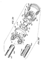
- Figure 3A is a perspective, exploded view of one of the inlet gas-control valves;
- Figure 3B shares the view of Figure 3A, representing the other of the inlet gas -control valves; figures 2, 3A and 3B also being partially cross-sectioned;
- Figure 4 is a plan view of the valve plate and dampening plate of the novel valve; and
- Figure 5 is an enlarged, cross-sectional view, taken through a limited, center portion of a discharge valve according to the invention.
- As shown in Figure 1, a
straight cylinder 10 defines therewithin a gas-comprssion chamber 12. Ends of the cylinder have centrally-threadedend closures cylinder 10 by means of tie bolts 18 (only two of the four thereof being visible). Thecylinder 10 hasgas inlet ports 20 formed therein for admission of gas via inlet conduits 22 (shown only in phantom). The cylinder also has agas discharge port 24 formed therein intermediate the ends thereof. -
End closure 14 threadedly receives the central bolt of aninlet valve 26, whereasend closure 16 threadedly receives the central bolt of aninlet valve 28. Therebetween, reciprocably mounted within thechamber 12, is thenovel valve assembly 30. - Figure 2 shows the
valve assembly 30 in greatly englarged detail. It comprises abolt 32 which is hollow, and which has external threads formed thereon at opposite ends thereof. The assembly comprises a pair ofvalve sets 33; as one is identical to the other, only one such set is shown. Thebolt 32 hasshoulders 34 formed thereabout, and spaced apart, adjacent to the opposite ends thereof. Assembled, eachshoulder 34 receives a ported,valve guard 36 thereagainst, the guard being centrally apertured. Theguard 36 has aperipheral wall 38 in which is received adampening plate 40.Compression springs 42, which are nested inblind holes 44 formed in theguard 36, bear against the underside of the dampening plate. Aguide ring 46, which has a reduced diameter portion 46a at one end thereof, is received in the apertured center of thedampening plate 40.Ring 46 is provided to limit the lift of thedampening plate 40. Set about thebolt 32 is avalve plate 48, it too being centrally apertured, slidably to receive the guide ring therewithin. Compression springs 50, which also are nested inblind holes 52 formed in theguard 36, are in penetration ofholes 54 formed therefor in the dampeningplate 40, and bias thevalve plate 48 away from theguard 38. The dampeningplate 40, biased away from theguard 36 bysprings 42, cooperates with thesprings 50 to dampen an impact of thevalve plate 48 with theguard 36.Plate 40intercepts plate 48 when the latter closes towardguard 36. A centrally apertured and threadedvalve seat 56 is threadedly engaged with the threads at one end of thebolt 32. With its threaded engagement with thebolt 32, theseat 56 clamps together theguard 36,plate 40,guide ring 46, andvalve plate 48; too, it holds in position arider ring 58 which is set about thewall 38 and against alip 60 which circumscribes the guard, 36. - The
guide ring 46 keeps the dampeningplate 40 distanced from thevalve seat 56, however theplate 48 freely translates along the outer surface of thering 46. Thering 46 sets against theseat 56 at one end thereof, and the opposite end ofring 46 sets against theguard 36. Anouter shoulder 46b, formed on thering 46, limits the lift of theplate 40 to the minimal depth of the reduced diameter portion 46a, in that theplate 40 closes against theshoulder 46b. - As is quite conventional, and as can be seen in the figures, and in particular Figure 5, the
guard 36, dampeningplate 40 andvalve plate 48, have mutually aligned ports formed therein to permit the flow of gas directly therethrough. Thevalve seat 56, too, is ported; however the ports therein are not in alignment with the ports inguard 36,plate 40, andplate 48. Rather, the ports invalve seat 56 are occluded by theplate 48.Plate 48 must remove from theseat 56 to permit fluid flow through theseat 56. When Whenassembly 30 translates to the right (with reference to Figure 1) a gas pressure, built up in thechamber 12 betweenAssembly 30 andinlet valve 28, causesplate 48 to remove from theseat 56; this allows the pressured gas to pass through the aforesaid porting inplate 48,plate 40 andguard 36, for exit thereof through thedischarge port 24. When theassembly 30 translates to the left (Figure 1), theplate 48 closes against theseat 56 and, consequently, a vacuum pressure is created betweenassembly 30 andinlet valve 28. This causes an ingestion of gas, viaport 20, intochamber 12.Valve assembly 30, with both valve sets 33 emplaced thereon, is reciprocable inchamber 12 and, consequently, one of thesets 33 is closed while the other is open to the flow therethrough of gas.Bolt 32 is threaded internally, at 62, threadedly to receive the threaded end of apiston rod 64. The latter is so-called, in that thevalve assembly 30 functions as a dual-headed piston. Thevalve seat 56 has a pair ofgrooves 66 formed therein and thereabout. Thegrooves 66 receivepiston rings 68 herein to effect a sealing engagement thereof with the inner surface of thechamber 12. By this expedient, with identical valve sets 33 on opposite ends of thebolt 32, the valve sets serve as the pistons, and are wholly confined within the chamber, functioning as well as the discharge valves. Analignment pin 69 is received in holes provided therefor inguard 36 andseat 56, at ends of thepin 69, and the pin penetrates theplates - In Figures 3A and 3B, same or similar index numbers, as those shown in Figure 1 and 2, denote same or similar elements.
- Figure 3A depicts an inlet valve which is received in the
end closure 16, and it is identical, in all respects except one, to valve set(s) 33 of Figure 2. Instead ofbolt 32, it has a bolt 32a. The latter is of short length and is hollow. The hollow interior accommodates the reciprocation of thepiston rod 64. The porting of components shown in Figure 3A is such (and, again, identical to the valve sets 33) as to close against the flow of gas as thevalve assembly 30 approaches, and to open as the valve assembly moves away therefrom. - In Figure 3B is depicted another inlet valve, albeit the one received in the
end closure 14. Save for thecentral bolt 32b, it too is identical to valve sets 33. Whereas bolt 32a of Figure 3A is hollow, to receive thepiston rod 64, bolt 34b is of solid cross-section. For simplicity, Figures 3A and 3B share the depiction of the components of each inlet valve; the only difference therebetween reside in the center bolts 32a (Figure 3A) and 32b (Figure 3B). They are otherwise identical. - Figure 4 illustrates a particularly novel feature of the valve sets 33, the same being a plan view of the dampening
plate 40 andvalve guard 36. The inner periphery fo thewall 38 is truly circular, whereas the confronting periphery of the dampening plate is trochoidal. Consequently,chordal voids 70 are formed between the aforesaid peripheries to enhance gas flow therethrough. Thevoids 70 present large, open areas, between theperipheral wall 38 ofguard 36 and theplate 40, to allow gas to course freely therethrough into the outermost ports inguard 36. The trochoidal configuration of the dampeningplate 40 defines portions of the plate with relatively narrow and wide sectors. Theholes 54, provided inplate 40 for thesprings 50, are formed in the wider sectors of the plate, as shown in Figure 4.
Claims (11)
- The combination of a gas-control valve (30) and a straight-cylinder, gas-compression chamber (12) having end closures (14, 16), the gas control valve being reciprocably confined within, and sealingly engaged with the inner surface of, said gas-compression chamber, characterized in that the combination further comprises:
a ported valve seat (56);
a ported valve guard (36);
a ported valve plate (48) interposed between said seat (56) and guard (36); and
a bolt (32), for mounting of said seat (56), guard (36) and plate (48) thereon, having (a) external threads formed thereon, and (b) an annular shoulder (34) formed thereabout; wherein
said seat (56), guard (36), and plate (48) are centrally apertured;
said guard (36) is set about said bolt (32), and against said shoulder (34);
said seat (56) is (a) internally threaded, (b) threadedly engaged with said bolt threads, and (c) has replaceable sealing means (68) engaged with the periphery (66) thereof:
said seat (56) and guard (36) are circular; and including
a dampening plate (40) interposed between said valve plate (48) and said valve guard (36); and wherein
said valve guard (36) and said dampening plate (40) have mutually confronting peripheral surfaces;
said peripheral surface of said guard (36) is circular; and
said peripheral surface of said dampening plate (40) is trochoidal. - A combination according to claim 1, wherein:
said valve seat (56) has a plurality of grooves formed therein and about the periphery thereof; and
piston rings (68) are set in said grooves. - A combination according to claim 1, wherein:
said bolt (32) is hollow. - A combination according to claim 1, wherein:
said bolt (32) is hollow, and has internal threads formed therein. - A combination according to claim 4, further including:
a piston rod (64), threaded at an end thereof, threadedly engaged with said internal threads of said hollow bolt (32), and in penetration of one of said end closures (14, 16). - A combination according to claim 1, further including:
means interposed between said valve guard (36) and said valve plate (48) biasing said valve plate (48) toward said valve seat (56); and
said biasing means is in penetration of said dampening plate (40). - The combination of a gas-control valve (26,28) and a straight-cylinder, gas-compression chamber (12) having centrally-threaded end closures (14, 16), the gas-control valve being confined within said gas-compression chamber (12) and sealingly engaged with the inner surface of said chamber (12), the combination further comprising:
a ported valve seat (56);
a ported valve guard (36);
a ported valve plate (48) interposed between said seat (56) and guard (36); and
a bolt (32), for mounting of said seat (56), guard (36) and plate (48) thereon, having (a) external threads formed thereon, and (b) an annular shoulder (34) formed thereabout; wherein
said seat (56), guard (36), and plate (48) are centrally apertured;
said guard (36) is set about said bolt (32), and against said shoulder (34);
said seat (56) is (a) internally threaded, (b) threadedly engaged with said bolt threads, and (c) has replaceable sealing means (68) engaged with the periphery thereof; and
said bolt (32) is threadedly engaged with one of said centrally-threaded end closures of said chamber (12). - A combination according to claim 7, wherein:
said bolt (32) is hollow. - A combination according to claim 7, wherein:
said bolt (32) is solid in cross-section. - A valve assembly (30), for use in combination with a straight-cylinder, gas-compression chamber (12), comprising:
a bolt (32);
said bolt (32) having (a) external threads formed thereon at opposite ends thereof, and (b) annular shoulders (34) formed thereabout, intermediate said threaded, opposite ends;
a pair of ported valve seats (56);
a pair of ported valve guards (36); and
a pair of ported valve plates (48); wherein
each seat (56) and guard (36) has one of said valve plates (48) interposed therebetween;
said seats (56), guards (36) and valve plates (48) are centrally apertured;
each guard (36) is set about said bolt (32), and against one of said shoulders (34); and
each seat (56) is (a) internally threaded, (b) threadedly engaged with one of said opposite ends of said bolt (32), and (c) has replaceable sealing means (68) engaged with the periphery thereof; wherein
said seats (56) and guards (36) are circular; and including
a dampening plate (40) interposed between each said valve plate (48) and valve guard (36);
each said valve guard (36) and dampening plate (40) have mutually confronting, peripheral surfaces;
said peripheral surface of each of said guards (36) is circular; and
said peripheral surface of each of said dampening plates (40) is trochoidal. - A valve assembly (30), according to claim 10, wherein:
said bolt (32) is hollow, and has threads formed therein.
Priority Applications (3)
| Application Number | Priority Date | Filing Date | Title |
|---|---|---|---|
| DE1991604182 DE69104182T2 (en) | 1991-02-14 | 1991-02-14 | Valve assembly for use in a straight cylinder with gas compression space. |
| ES91301189T ES2060291T3 (en) | 1991-02-14 | 1991-02-14 | VALVE ASSEMBLY, FOR USE WITH A GAS COMPRESSION CHAMBER THAT HAS A STRAIGHT CYLINDER. |
| EP19910301189 EP0498980B1 (en) | 1991-02-14 | 1991-02-14 | Valve assembly, for use with a straight-cylinder having a gas-compression chamber |
Applications Claiming Priority (1)
| Application Number | Priority Date | Filing Date | Title |
|---|---|---|---|
| EP19910301189 EP0498980B1 (en) | 1991-02-14 | 1991-02-14 | Valve assembly, for use with a straight-cylinder having a gas-compression chamber |
Publications (2)
| Publication Number | Publication Date |
|---|---|
| EP0498980A1 EP0498980A1 (en) | 1992-08-19 |
| EP0498980B1 true EP0498980B1 (en) | 1994-09-21 |
Family
ID=8208191
Family Applications (1)
| Application Number | Title | Priority Date | Filing Date |
|---|---|---|---|
| EP19910301189 Expired - Lifetime EP0498980B1 (en) | 1991-02-14 | 1991-02-14 | Valve assembly, for use with a straight-cylinder having a gas-compression chamber |
Country Status (3)
| Country | Link |
|---|---|
| EP (1) | EP0498980B1 (en) |
| DE (1) | DE69104182T2 (en) |
| ES (1) | ES2060291T3 (en) |
Cited By (1)
| Publication number | Priority date | Publication date | Assignee | Title |
|---|---|---|---|---|
| US9822877B2 (en) | 2013-09-16 | 2017-11-21 | Ariel Corporation | Lightweight compressor piston with opening |
Family Cites Families (7)
| Publication number | Priority date | Publication date | Assignee | Title |
|---|---|---|---|---|
| US1602193A (en) * | 1922-12-04 | 1926-10-05 | Deming Co | Pump |
| DE688429C (en) * | 1938-04-26 | 1940-02-20 | Hoerbiger & Co | DC compressor |
| CH467956A (en) * | 1968-08-30 | 1969-01-31 | Burckhardt Ag Maschf | Cylinders with pistons for compressors and pumps for very high pressures |
| DE2017248A1 (en) * | 1970-04-10 | 1971-10-21 | ENFO, Entwicklungs- und Forschungs-Aktiengesellschaft, Vaduz | Plate valve for reciprocating compressors |
| AT398809B (en) * | 1987-07-01 | 1995-02-27 | Hoerbiger Ventilwerke Ag | DISC VALVE FOR A COMPRESSOR |
| US4723572A (en) * | 1987-07-20 | 1988-02-09 | Hoerbiger Corporation Of America, Inc. | Compressor valve |
| US5011383A (en) * | 1990-01-02 | 1991-04-30 | Dresser-Rand Company | Valve assembly, for use in combination with a straight-cylinder, gas-compression chamber, and in combination therewith |
-
1991
- 1991-02-14 ES ES91301189T patent/ES2060291T3/en not_active Expired - Lifetime
- 1991-02-14 EP EP19910301189 patent/EP0498980B1/en not_active Expired - Lifetime
- 1991-02-14 DE DE1991604182 patent/DE69104182T2/en not_active Expired - Fee Related
Cited By (1)
| Publication number | Priority date | Publication date | Assignee | Title |
|---|---|---|---|---|
| US9822877B2 (en) | 2013-09-16 | 2017-11-21 | Ariel Corporation | Lightweight compressor piston with opening |
Also Published As
| Publication number | Publication date |
|---|---|
| DE69104182T2 (en) | 1995-05-11 |
| EP0498980A1 (en) | 1992-08-19 |
| DE69104182D1 (en) | 1994-10-27 |
| ES2060291T3 (en) | 1994-11-16 |
Similar Documents
| Publication | Publication Date | Title |
|---|---|---|
| US5011383A (en) | Valve assembly, for use in combination with a straight-cylinder, gas-compression chamber, and in combination therewith | |
| US5645100A (en) | Hand pump for engaging with different tire valves | |
| CA1224115A (en) | Hydraulic cylinder locking device | |
| CA1146838A (en) | Plate valve | |
| US20030017067A1 (en) | Compressor having an improved valved piston device | |
| JPH0353477B2 (en) | ||
| JPH08226383A (en) | Reed valve for compressor-vacuum pump | |
| CA2266407A1 (en) | Gate valve seat | |
| CN107795451A (en) | Integrated high pressure oil pump | |
| EP1452735B1 (en) | Compressor valve plate | |
| CA2089413A1 (en) | Compressor suction and discharge valve assembly | |
| EP0371407A3 (en) | Ring valve type air compressor | |
| US5180443A (en) | Pressure-relief valve with stepped or double piston | |
| US3679333A (en) | Packing for air compressor valve | |
| US4793591A (en) | Hydraulic shear seal valve including slide bearing | |
| US3665816A (en) | Power cylinder construction | |
| EP0498980A1 (en) | Valve assembly, for use with a straight-cylinder having a gas-compression chamber | |
| CA2035613C (en) | Valve assembly, for use in combination with a straight-cylinder, gas-compression chamber, and in combination therewith | |
| KR20020082404A (en) | Seal structure of compressor and compressor having the same | |
| EP1404971B1 (en) | Double acting simplex plunger pump with bi-directional valves | |
| US3982765A (en) | Piston pump | |
| KR100565480B1 (en) | Inlet structure of linear compressor | |
| CN110645225B (en) | High-pressure protection device for hydraulic cylinder | |
| JPH1122703A (en) | Rotary actuator | |
| JPH0478310U (en) |
Legal Events
| Date | Code | Title | Description |
|---|---|---|---|
| PUAI | Public reference made under article 153(3) epc to a published international application that has entered the european phase |
Free format text: ORIGINAL CODE: 0009012 |
|
| AK | Designated contracting states |
Kind code of ref document: A1 Designated state(s): DE ES FR GB IT NL |
|
| 17P | Request for examination filed |
Effective date: 19930119 |
|
| 17Q | First examination report despatched |
Effective date: 19930413 |
|
| GRAA | (expected) grant |
Free format text: ORIGINAL CODE: 0009210 |
|
| AK | Designated contracting states |
Kind code of ref document: B1 Designated state(s): DE ES FR GB IT NL |
|
| ITF | It: translation for a ep patent filed | ||
| REF | Corresponds to: |
Ref document number: 69104182 Country of ref document: DE Date of ref document: 19941027 |
|
| REG | Reference to a national code |
Ref country code: ES Ref legal event code: FG2A Ref document number: 2060291 Country of ref document: ES Kind code of ref document: T3 |
|
| ET | Fr: translation filed | ||
| PLBE | No opposition filed within time limit |
Free format text: ORIGINAL CODE: 0009261 |
|
| STAA | Information on the status of an ep patent application or granted ep patent |
Free format text: STATUS: NO OPPOSITION FILED WITHIN TIME LIMIT |
|
| 26N | No opposition filed | ||
| REG | Reference to a national code |
Ref country code: GB Ref legal event code: IF02 |
|
| PGFP | Annual fee paid to national office [announced via postgrant information from national office to epo] |
Ref country code: FR Payment date: 20040202 Year of fee payment: 14 |
|
| PGFP | Annual fee paid to national office [announced via postgrant information from national office to epo] |
Ref country code: ES Payment date: 20040216 Year of fee payment: 14 |
|
| PG25 | Lapsed in a contracting state [announced via postgrant information from national office to epo] |
Ref country code: ES Free format text: LAPSE BECAUSE OF NON-PAYMENT OF DUE FEES Effective date: 20050215 |
|
| PGFP | Annual fee paid to national office [announced via postgrant information from national office to epo] |
Ref country code: DE Payment date: 20050331 Year of fee payment: 15 |
|
| PG25 | Lapsed in a contracting state [announced via postgrant information from national office to epo] |
Ref country code: FR Free format text: LAPSE BECAUSE OF NON-PAYMENT OF DUE FEES Effective date: 20051031 |
|
| REG | Reference to a national code |
Ref country code: FR Ref legal event code: ST Effective date: 20051031 |
|
| REG | Reference to a national code |
Ref country code: ES Ref legal event code: FD2A Effective date: 20050215 |
|
| PG25 | Lapsed in a contracting state [announced via postgrant information from national office to epo] |
Ref country code: DE Free format text: LAPSE BECAUSE OF NON-PAYMENT OF DUE FEES Effective date: 20060901 |
|
| PGFP | Annual fee paid to national office [announced via postgrant information from national office to epo] |
Ref country code: IT Payment date: 20090331 Year of fee payment: 19 |
|
| PGFP | Annual fee paid to national office [announced via postgrant information from national office to epo] |
Ref country code: GB Payment date: 20100224 Year of fee payment: 20 |
|
| PGFP | Annual fee paid to national office [announced via postgrant information from national office to epo] |
Ref country code: NL Payment date: 20100223 Year of fee payment: 20 |
|
| REG | Reference to a national code |
Ref country code: NL Ref legal event code: V4 Effective date: 20110214 |
|
| REG | Reference to a national code |
Ref country code: GB Ref legal event code: PE20 Expiry date: 20110213 |
|
| PG25 | Lapsed in a contracting state [announced via postgrant information from national office to epo] |
Ref country code: IT Free format text: LAPSE BECAUSE OF NON-PAYMENT OF DUE FEES Effective date: 20100214 |
|
| PG25 | Lapsed in a contracting state [announced via postgrant information from national office to epo] |
Ref country code: NL Free format text: LAPSE BECAUSE OF EXPIRATION OF PROTECTION Effective date: 20110214 |
|
| PG25 | Lapsed in a contracting state [announced via postgrant information from national office to epo] |
Ref country code: GB Free format text: LAPSE BECAUSE OF EXPIRATION OF PROTECTION Effective date: 20110213 |