EP0498123A1 - Bottle with handle - Google Patents
Bottle with handle Download PDFInfo
- Publication number
- EP0498123A1 EP0498123A1 EP91311990A EP91311990A EP0498123A1 EP 0498123 A1 EP0498123 A1 EP 0498123A1 EP 91311990 A EP91311990 A EP 91311990A EP 91311990 A EP91311990 A EP 91311990A EP 0498123 A1 EP0498123 A1 EP 0498123A1
- Authority
- EP
- European Patent Office
- Prior art keywords
- bottle
- ear
- mounting
- mounting ring
- edge
- Prior art date
- Legal status (The legal status is an assumption and is not a legal conclusion. Google has not performed a legal analysis and makes no representation as to the accuracy of the status listed.)
- Granted
Links
Images


Classifications
-
- B—PERFORMING OPERATIONS; TRANSPORTING
- B65—CONVEYING; PACKING; STORING; HANDLING THIN OR FILAMENTARY MATERIAL
- B65D—CONTAINERS FOR STORAGE OR TRANSPORT OF ARTICLES OR MATERIALS, e.g. BAGS, BARRELS, BOTTLES, BOXES, CANS, CARTONS, CRATES, DRUMS, JARS, TANKS, HOPPERS, FORWARDING CONTAINERS; ACCESSORIES, CLOSURES, OR FITTINGS THEREFOR; PACKAGING ELEMENTS; PACKAGES
- B65D23/00—Details of bottles or jars not otherwise provided for
- B65D23/10—Handles
- B65D23/104—Handles formed separately
- B65D23/106—Handles formed separately the gripping region of the handle extending between the neck and the base of the bottle or jar and being located in a radial plane comprising the axis of the bottle or jar
-
- B—PERFORMING OPERATIONS; TRANSPORTING
- B29—WORKING OF PLASTICS; WORKING OF SUBSTANCES IN A PLASTIC STATE IN GENERAL
- B29C—SHAPING OR JOINING OF PLASTICS; SHAPING OF MATERIAL IN A PLASTIC STATE, NOT OTHERWISE PROVIDED FOR; AFTER-TREATMENT OF THE SHAPED PRODUCTS, e.g. REPAIRING
- B29C49/00—Blow-moulding, i.e. blowing a preform or parison to a desired shape within a mould; Apparatus therefor
- B29C49/02—Combined blow-moulding and manufacture of the preform or the parison
- B29C49/06—Injection blow-moulding
-
- B—PERFORMING OPERATIONS; TRANSPORTING
- B29—WORKING OF PLASTICS; WORKING OF SUBSTANCES IN A PLASTIC STATE IN GENERAL
- B29C—SHAPING OR JOINING OF PLASTICS; SHAPING OF MATERIAL IN A PLASTIC STATE, NOT OTHERWISE PROVIDED FOR; AFTER-TREATMENT OF THE SHAPED PRODUCTS, e.g. REPAIRING
- B29C49/00—Blow-moulding, i.e. blowing a preform or parison to a desired shape within a mould; Apparatus therefor
- B29C49/071—Preforms or parisons characterised by their configuration, e.g. geometry, dimensions or physical properties
-
- B—PERFORMING OPERATIONS; TRANSPORTING
- B29—WORKING OF PLASTICS; WORKING OF SUBSTANCES IN A PLASTIC STATE IN GENERAL
- B29C—SHAPING OR JOINING OF PLASTICS; SHAPING OF MATERIAL IN A PLASTIC STATE, NOT OTHERWISE PROVIDED FOR; AFTER-TREATMENT OF THE SHAPED PRODUCTS, e.g. REPAIRING
- B29C49/00—Blow-moulding, i.e. blowing a preform or parison to a desired shape within a mould; Apparatus therefor
- B29C49/02—Combined blow-moulding and manufacture of the preform or the parison
- B29C2049/023—Combined blow-moulding and manufacture of the preform or the parison using inherent heat of the preform, i.e. 1 step blow moulding
-
- B—PERFORMING OPERATIONS; TRANSPORTING
- B29—WORKING OF PLASTICS; WORKING OF SUBSTANCES IN A PLASTIC STATE IN GENERAL
- B29C—SHAPING OR JOINING OF PLASTICS; SHAPING OF MATERIAL IN A PLASTIC STATE, NOT OTHERWISE PROVIDED FOR; AFTER-TREATMENT OF THE SHAPED PRODUCTS, e.g. REPAIRING
- B29C49/00—Blow-moulding, i.e. blowing a preform or parison to a desired shape within a mould; Apparatus therefor
- B29C49/42—Component parts, details or accessories; Auxiliary operations
- B29C49/48—Moulds
- B29C2049/4879—Moulds characterised by mould configurations
- B29C2049/4882—Mould cavity geometry
- B29C2049/48825—Asymmetric moulds, i.e. the parison is not in the center of the mould
-
- B—PERFORMING OPERATIONS; TRANSPORTING
- B29—WORKING OF PLASTICS; WORKING OF SUBSTANCES IN A PLASTIC STATE IN GENERAL
- B29C—SHAPING OR JOINING OF PLASTICS; SHAPING OF MATERIAL IN A PLASTIC STATE, NOT OTHERWISE PROVIDED FOR; AFTER-TREATMENT OF THE SHAPED PRODUCTS, e.g. REPAIRING
- B29C2949/00—Indexing scheme relating to blow-moulding
- B29C2949/07—Preforms or parisons characterised by their configuration
- B29C2949/072—Preforms or parisons characterised by their configuration having variable wall thickness
- B29C2949/0723—Preforms or parisons characterised by their configuration having variable wall thickness at flange portion
-
- B—PERFORMING OPERATIONS; TRANSPORTING
- B29—WORKING OF PLASTICS; WORKING OF SUBSTANCES IN A PLASTIC STATE IN GENERAL
- B29C—SHAPING OR JOINING OF PLASTICS; SHAPING OF MATERIAL IN A PLASTIC STATE, NOT OTHERWISE PROVIDED FOR; AFTER-TREATMENT OF THE SHAPED PRODUCTS, e.g. REPAIRING
- B29C2949/00—Indexing scheme relating to blow-moulding
- B29C2949/07—Preforms or parisons characterised by their configuration
- B29C2949/072—Preforms or parisons characterised by their configuration having variable wall thickness
- B29C2949/0724—Preforms or parisons characterised by their configuration having variable wall thickness at body portion
-
- B—PERFORMING OPERATIONS; TRANSPORTING
- B29—WORKING OF PLASTICS; WORKING OF SUBSTANCES IN A PLASTIC STATE IN GENERAL
- B29C—SHAPING OR JOINING OF PLASTICS; SHAPING OF MATERIAL IN A PLASTIC STATE, NOT OTHERWISE PROVIDED FOR; AFTER-TREATMENT OF THE SHAPED PRODUCTS, e.g. REPAIRING
- B29C2949/00—Indexing scheme relating to blow-moulding
- B29C2949/07—Preforms or parisons characterised by their configuration
- B29C2949/073—Preforms or parisons characterised by their configuration having variable diameter
- B29C2949/0732—Preforms or parisons characterised by their configuration having variable diameter at flange portion
-
- B—PERFORMING OPERATIONS; TRANSPORTING
- B29—WORKING OF PLASTICS; WORKING OF SUBSTANCES IN A PLASTIC STATE IN GENERAL
- B29C—SHAPING OR JOINING OF PLASTICS; SHAPING OF MATERIAL IN A PLASTIC STATE, NOT OTHERWISE PROVIDED FOR; AFTER-TREATMENT OF THE SHAPED PRODUCTS, e.g. REPAIRING
- B29C2949/00—Indexing scheme relating to blow-moulding
- B29C2949/07—Preforms or parisons characterised by their configuration
- B29C2949/073—Preforms or parisons characterised by their configuration having variable diameter
- B29C2949/0733—Preforms or parisons characterised by their configuration having variable diameter at body portion
-
- B—PERFORMING OPERATIONS; TRANSPORTING
- B29—WORKING OF PLASTICS; WORKING OF SUBSTANCES IN A PLASTIC STATE IN GENERAL
- B29C—SHAPING OR JOINING OF PLASTICS; SHAPING OF MATERIAL IN A PLASTIC STATE, NOT OTHERWISE PROVIDED FOR; AFTER-TREATMENT OF THE SHAPED PRODUCTS, e.g. REPAIRING
- B29C2949/00—Indexing scheme relating to blow-moulding
- B29C2949/07—Preforms or parisons characterised by their configuration
- B29C2949/076—Preforms or parisons characterised by their configuration characterised by the shape
- B29C2949/0768—Preforms or parisons characterised by their configuration characterised by the shape characterised by the shape of specific parts of preform
- B29C2949/077—Preforms or parisons characterised by their configuration characterised by the shape characterised by the shape of specific parts of preform characterised by the neck
- B29C2949/0772—Closure retaining means
- B29C2949/0773—Threads
-
- B—PERFORMING OPERATIONS; TRANSPORTING
- B29—WORKING OF PLASTICS; WORKING OF SUBSTANCES IN A PLASTIC STATE IN GENERAL
- B29C—SHAPING OR JOINING OF PLASTICS; SHAPING OF MATERIAL IN A PLASTIC STATE, NOT OTHERWISE PROVIDED FOR; AFTER-TREATMENT OF THE SHAPED PRODUCTS, e.g. REPAIRING
- B29C2949/00—Indexing scheme relating to blow-moulding
- B29C2949/07—Preforms or parisons characterised by their configuration
- B29C2949/076—Preforms or parisons characterised by their configuration characterised by the shape
- B29C2949/0768—Preforms or parisons characterised by their configuration characterised by the shape characterised by the shape of specific parts of preform
- B29C2949/0779—Preforms or parisons characterised by their configuration characterised by the shape characterised by the shape of specific parts of preform characterised by the body
-
- B—PERFORMING OPERATIONS; TRANSPORTING
- B29—WORKING OF PLASTICS; WORKING OF SUBSTANCES IN A PLASTIC STATE IN GENERAL
- B29C—SHAPING OR JOINING OF PLASTICS; SHAPING OF MATERIAL IN A PLASTIC STATE, NOT OTHERWISE PROVIDED FOR; AFTER-TREATMENT OF THE SHAPED PRODUCTS, e.g. REPAIRING
- B29C2949/00—Indexing scheme relating to blow-moulding
- B29C2949/20—Preforms or parisons whereby a specific part is made of only one component, e.g. only one layer
- B29C2949/22—Preforms or parisons whereby a specific part is made of only one component, e.g. only one layer at neck portion
-
- B—PERFORMING OPERATIONS; TRANSPORTING
- B29—WORKING OF PLASTICS; WORKING OF SUBSTANCES IN A PLASTIC STATE IN GENERAL
- B29C—SHAPING OR JOINING OF PLASTICS; SHAPING OF MATERIAL IN A PLASTIC STATE, NOT OTHERWISE PROVIDED FOR; AFTER-TREATMENT OF THE SHAPED PRODUCTS, e.g. REPAIRING
- B29C2949/00—Indexing scheme relating to blow-moulding
- B29C2949/20—Preforms or parisons whereby a specific part is made of only one component, e.g. only one layer
- B29C2949/24—Preforms or parisons whereby a specific part is made of only one component, e.g. only one layer at flange portion
-
- B—PERFORMING OPERATIONS; TRANSPORTING
- B29—WORKING OF PLASTICS; WORKING OF SUBSTANCES IN A PLASTIC STATE IN GENERAL
- B29C—SHAPING OR JOINING OF PLASTICS; SHAPING OF MATERIAL IN A PLASTIC STATE, NOT OTHERWISE PROVIDED FOR; AFTER-TREATMENT OF THE SHAPED PRODUCTS, e.g. REPAIRING
- B29C2949/00—Indexing scheme relating to blow-moulding
- B29C2949/20—Preforms or parisons whereby a specific part is made of only one component, e.g. only one layer
- B29C2949/26—Preforms or parisons whereby a specific part is made of only one component, e.g. only one layer at body portion
-
- B—PERFORMING OPERATIONS; TRANSPORTING
- B29—WORKING OF PLASTICS; WORKING OF SUBSTANCES IN A PLASTIC STATE IN GENERAL
- B29C—SHAPING OR JOINING OF PLASTICS; SHAPING OF MATERIAL IN A PLASTIC STATE, NOT OTHERWISE PROVIDED FOR; AFTER-TREATMENT OF THE SHAPED PRODUCTS, e.g. REPAIRING
- B29C2949/00—Indexing scheme relating to blow-moulding
- B29C2949/20—Preforms or parisons whereby a specific part is made of only one component, e.g. only one layer
- B29C2949/28—Preforms or parisons whereby a specific part is made of only one component, e.g. only one layer at bottom portion
-
- B—PERFORMING OPERATIONS; TRANSPORTING
- B29—WORKING OF PLASTICS; WORKING OF SUBSTANCES IN A PLASTIC STATE IN GENERAL
- B29L—INDEXING SCHEME ASSOCIATED WITH SUBCLASS B29C, RELATING TO PARTICULAR ARTICLES
- B29L2031/00—Other particular articles
- B29L2031/46—Knobs or handles, push-buttons, grips
- B29L2031/463—Grips, handles
Definitions
- This invention relates to a bottle with an ear made of synthetic resin prepared by injection orientation blow molding.
- Molding of such a bottle can be achieved by a cold parison system which molds a preform using a normal injection mold to mold the preform into a bottle by an orientation blow molding machine, but has been difficult to be employed in case of a hot parison system in which an operation from injection molding of a preform to orientation blow molding is carried out by a single apparatus.
- the mouth portion of the bottle with an ear is formed to be longer than that of a normal bottle and a position at which an ear is mounted is high. Therefore, particularly in a large bottle, it is difficult to incline the bottle while holding the ear, often wanting in smooth pouring of contents.
- the thread of the mouth portion, the support ring and the like remain injection molded with a view to maintaining molding accuracy, and making the wall portion thin by the orientation blow molding is carried out from the underside of the support ring. For this reason, in the case where a large diameter portion having threads is formed below the support ring to threadedly mount an ear thereon, portions up to the large diameter portion need to leave therein a thick-wall portion resulted from injection molding. As a result, the use of material per bottle increases, thus increasing cost.
- the orientation blow molding has the merit in that since portions other than the mouth portion can be molded to have a thin wall-thickness, there can be obtained a bottle which is lighter than that obtained by the normal blow molding and is excellent in falling strength, because of which an increase of non-oriented portions left to be thin in wall-thickness is not unpreferable, and accordingly, a position of a large diameter portion at which an ear is mounted is limited to a portion near the mouth portion.
- a screw mounts an ear by means of a screw causes the ear to be easily loosened due to vibrations or the like, and a lower end of the ear is not connected to the body of a bottle and in a state in which the ear is easily disengaged.
- the load is concentrated on a bended portion at the upper portion of the ear to generate a flexture thereat.
- a gripping portion thereof is opened.
- an ear is mounted on a molded bottle later but a mounting portion of the ear is molded to have a thin wall-thickness and mounted below a support ring whereby a position of the ear mounting portion can be set downwardly, thus solving the problem encountered in a conventional bottle with an ear in which the mounting position is apt to be limited to a portion near the mouth portion.
- a mounting portion to be located at a predetermined height which is larger in diameter than that of a mouth portion and of which upper edge is formed to be edged is subjected to orientation blow molding, but the upper edge formed to be edged maintains its injection molded state and the upper edge and a ring member formed integral with a base end of the ear are fitted with each other whereby the ear is mounted positively and without being loosened, thus solving the problem encountered in a conventional bottle with an ear.
- an ear is mounted on a molded bottle later but a lower end of the ear can be firmly fixed to the body of the bottle by extremely simple means, thus solving the problem encountered in a conventional bottle with an ear in which a gripping portion thereof is opened due to the load when the bottle is inclined.
- a mounting portion positioned at a predetermined height which has a large diameter and has a mounting groove having a predetermined width in an outer periphery thereof is formed below a mouth portion of a bottle by injection orientation blow molding, an upper edge of said mounting groove is formed to have an edge having a plurality of notches at equal intervals, a mounting ring internally provided with a plurality of projecting surfaces positioned at the mounting groove through said notches is formed integral with a bended end of an ear, and the projecting surfaces of said mounting ring and the upper edge of said mounting groove are fitted with each other whereby the ear and the bottle are integrally connected.
- the upper portion of the ear mounting portion is composed of an outer wall of a flange injection molded below the mouth portion and an inner wall internally oriented and placed in close contact, and the upper edge fitted into the mounting ring is formed to be edged by an acute lower edge of the flange.
- the lower end of the ear mounted on the bottle is attached to the side of the body by means of a heat-shrinkable band fitted around the body of the bottle.
- the mounting portion of the ear is formed to have a large diameter, the insertion of a mounting ring is not impaired by the threads in the outer periphery of the mouth portion and the support ring but when the ear side is slightly turned, the upper edge of the mounting groove formed to have an edge and the upper edge of the projecting surface internally of the mounting ring are firmly engaged with each other. Therefore, mounting is simpler than the case which replied upon engagement between threads. Even if a load is imposed on the engaging portion, the ear is not disengaged unless the mounting ring is broken.
- the ear mounting portion is composed of a flange injection molded below the mouth portion and a wall portion oriented internally thereof and placed in close contact therewith, and other portions are subjected to orientation blow molding. Therefore, the ear can be formed to have a thin wall-thickness configuration as compared with the case where the whole mounting portion is subjected to injection molding.
- the upper portion has a strength due to the orientation of the inner wall portion, and a molding position thereof is not limited to a portion near the mouth portion.
- the lower end of the ear is attached to the side of the body by means of a heat-shrinkable band fitted around the body of the bottle, when the bottle is inclined, the load is not concentrated on only the upper portion of the ear by the integration of the lower end of the ear and the body. In addition, the gripping portion is not opened due to the load, and therefore, even a large bottle which is heavy because of contents can be easily handled.
- Fig. 1 is a longitudinal sectional side view of an upper half portion of a bottle.
- Fig. 2 is a plan view of a bottle.
- Fig. 3 is a side view of a bottle.
- Fig. 4 is a developed view of a mounting ring.
- Fig. 5 is a side view of a bottle with an ear in which a lower end of the ear is attached to a body of the bottle.
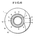
- Fig. 6 is a plan view of Fig. 5.
- Fig. 7 is a sectional view of essential parts of an injection mold for explaining the injection molding step of an upper edge of an ear mounting portion.
- Fig. 8 is a sectional view of essential parts of a blow mold for explaining the blow molding step of an ear mounting portion and an upper edge.
- reference numeral 1 designates a bottle form of polyethyleneterephtalate (PETP) subjected to injection orientation blow molding.
- PETP polyethyleneterephtalate
- a support ring 3 is provided below a mouth portion 2.
- a continuous portion to a body 11 below the support ring 3 of the bottle 1 is formed with an ear mounting portion 4 positioned at a predetermined height which is larger in diameter than the support ring 3, and a mounting groove 4a having a predetermined width is formed in the outer periphery thereof.
- the lower edge of the mounting groove 4a is connected to a curve portion of a shoulder 12 which forms an upper portion of the body 11, and an upper edge 5 is formed to be edged. At four locations of the upper edge 5, there are formed inserting notches 6 at equal intervals.
- Reference numeral 7 designates an ear formed of PETP, at an end of which is integrally formed a mounting ring 8.
- the mounting ring 8 is internally formed with four projecting surfaces 9 corresponding to the notches 6, and the upper edge of the projecting surfaces 9 is formed into a shoulder 10 which is fitted into the upper edge 5 of the mounting groove 4a.
- the upper edge of the projecting surface is provided with a recess 14 which is fitted into an attachment mechanism 13 projected on the upper edge 5 of the mounting groove 4a to prevent a lateral deviation of the mounting ring 8.
- the upper edge 5 of the ear mounting portion 4 is formed from an injection molded member.
- Figs. 7 and 8 explain the molding steps therefor.
- a neck mold 21, a cavity mold 22 and a core mold 23 are closed to injection mold a preform 24, a flange 27 whose lower edge 26 is acute along with threads 25 in the outer periphery of the mouth portion 2 and the support ring 3 are inwardly integrally molded below the mouth portion by making use of a parting portion between the neck mold 21 and the cavity mold 22.
- the preform 24 is held by the neck mold 21 above the flange 27 and transported to the blow mold 28, where the molds are closed. Thereby, the preform body below the lower edge 26 of the flange 27 is positioned at the blow cavity. Within the blow cavity, a space 29 is formed between the inside of the flange and the wall portion 24a of the preform indicated at the phantom line.
- the preform body is longitudinally oriented from the end of the flange 27 and also laterally expanded to form a bottle 1 having an ear mounting portion 4 having a large diameter below the flange.
- the preform wall portion 24a internally of the flange is extended to have a thin wall-thickness till coming into close contact with the inside of the flange by the space 29 internally of the flange 27, and a constriction thereunder constitutes a mounting groove 4a.
- notches 6 of the upper edge 5 are omitted in this step, it is to be noted that the notches 6 can be molded during molding of the flange.
- the mounting ring 8 is placed over the mounting groove 4a from the mouth portion, and positioning between the notches 6 and the projecting surfaces 9 internally of the mounting ring is carried out for insertion, after which the mounting ring 8 is forcibly turned. Then the projecting surfaces 5 are positioned under the upper edges 5 and firmly fitted.
- the ear 7 is mounted on the side of the bottle.
- the ear 7 is not disengaged from the bottle 1 unless the bottle 1 is held and the ear 7 is forcibly deviated laterally.
- Figs. 4 and 5 show a bottle in which a lower end 71 of the ear 7 is integrally attached to the body using a heat-shrinkable band 15.
- the heat-shrinkable band 15 is formed of PETP or the like.
- the band 15 before being shrunk has a larger in diameter than that of the body, and after the ear 7 has been mounted on the bottle 1, the band 5 is fitted from the top of the bottle into an annular groove 16 formed around the body.
- a portion of the annular groove 16 at which a lower end 71 of the ear 7 is positioned is formed with a recess 17.
- the heat-shrinkable band 15 is internally formed with a partial gap by the presence of the recess 17.
- the aforesaid lower end 71 is positioned at the gap, and the lower end 71 is firmly attached to the body due to the reduction in diameter of the heat-shrinkable band 15 caused by heating.
- the mounting ring 8 In mounting the ear 7, the mounting ring 8 is placed over the mounting groove 4, and the notches 6 and the projecting surfaces 9 internally of the mounting ring are adjusted in position and the ear 7 is inserted, after which the mounting ring 8 is forcibly turned, in a manner similar to the case shown in Fig. 1. Then, when the heat-shrinkable ring 15 is placed over the annular groove 16 and the ring 15 is heated by a conventional tunnel type heating device, the heat-shrinkable band 12 is reduced in diameter due to the shrinkage and placed in close contact with the body 11, and the lower end 71 of the ear 7 is pulled toward the body 11 due to the shrinking force and firmly attached.
- the lower end 71 of the ear 7 is also attached to the body 11 by means of the heat-shrinkable band 15. Therefore, the load is not concentrated on the upper portion of the ear as so experienced in the past, and when the bottle 1 is inclined, a gripping portion 72 is not opened due to the load. Therefore, the contents are easily poured as compared with the case where an ear is merely mounted on the mouth portion, and even a heavy large bottle is easily handled.
Abstract
Description
- This invention relates to a bottle with an ear made of synthetic resin prepared by injection orientation blow molding.
- In a bottle molded by injection molding a preform, and orientation blow molding portions other than a mouth portion of the preform into a thin wall-thickness configuration while holding said mouth portion, it is technically difficult to mold a part of the preform into an ear during orientation blow molding, unlike normal blow molding. Therefore, in case of mounting an ear, the ear is molded below the mouth portion integral with the preform.
- Molding of such a bottle can be achieved by a cold parison system which molds a preform using a normal injection mold to mold the preform into a bottle by an orientation blow molding machine, but has been difficult to be employed in case of a hot parison system in which an operation from injection molding of a preform to orientation blow molding is carried out by a single apparatus.
- In view of the foregoing, an attempt has been made to mount an ear after a bottle has been molded. In this case, however, a position at which an ear is mounted is limited to a portion above a support ring.
- Therefore, the mouth portion of the bottle with an ear is formed to be longer than that of a normal bottle and a position at which an ear is mounted is high. Therefore, particularly in a large bottle, it is difficult to incline the bottle while holding the ear, often wanting in smooth pouring of contents.
- Such a problem as just mentioned can be solved by an arrangement wherein a lower side of a mouth is formed to have a large diameter, and threads are provided in the outer periphery of the large diameter portion, to which the ear is threadedly mounted, as disclosed in British Registered Design No. 1,039,436. However, in the injection orientation blow molding, it is impossible to orientation blow mold portions up to the large diameter portion without impairing the dimension of the thread formed in the outer peripheral side.
- In the injection orientation blow molding, the thread of the mouth portion, the support ring and the like remain injection molded with a view to maintaining molding accuracy, and making the wall portion thin by the orientation blow molding is carried out from the underside of the support ring. For this reason, in the case where a large diameter portion having threads is formed below the support ring to threadedly mount an ear thereon, portions up to the large diameter portion need to leave therein a thick-wall portion resulted from injection molding. As a result, the use of material per bottle increases, thus increasing cost.
- The orientation blow molding has the merit in that since portions other than the mouth portion can be molded to have a thin wall-thickness, there can be obtained a bottle which is lighter than that obtained by the normal blow molding and is excellent in falling strength, because of which an increase of non-oriented portions left to be thin in wall-thickness is not unpreferable, and accordingly, a position of a large diameter portion at which an ear is mounted is limited to a portion near the mouth portion.
- Moreover, mounting of an ear by means of a screw causes the ear to be easily loosened due to vibrations or the like, and a lower end of the ear is not connected to the body of a bottle and in a state in which the ear is easily disengaged. When the bottle is inclined to pour the content, the load is concentrated on a bended portion at the upper portion of the ear to generate a flexture thereat. In case of an ear made of synthetic resin, a gripping portion thereof is opened.
-
- According to this invention, an ear is mounted on a molded bottle later but a mounting portion of the ear is molded to have a thin wall-thickness and mounted below a support ring whereby a position of the ear mounting portion can be set downwardly, thus solving the problem encountered in a conventional bottle with an ear in which the mounting position is apt to be limited to a portion near the mouth portion.
- Furthermore, according to this invention, a mounting portion to be located at a predetermined height which is larger in diameter than that of a mouth portion and of which upper edge is formed to be edged is subjected to orientation blow molding, but the upper edge formed to be edged maintains its injection molded state and the upper edge and a ring member formed integral with a base end of the ear are fitted with each other whereby the ear is mounted positively and without being loosened, thus solving the problem encountered in a conventional bottle with an ear.
- Moreover, according to this invention, an ear is mounted on a molded bottle later but a lower end of the ear can be firmly fixed to the body of the bottle by extremely simple means, thus solving the problem encountered in a conventional bottle with an ear in which a gripping portion thereof is opened due to the load when the bottle is inclined.
- According to a feature of this invention for achieving the aforesaid object, there is provided an arrangement wherein a mounting portion positioned at a predetermined height which has a large diameter and has a mounting groove having a predetermined width in an outer periphery thereof is formed below a mouth portion of a bottle by injection orientation blow molding, an upper edge of said mounting groove is formed to have an edge having a plurality of notches at equal intervals, a mounting ring internally provided with a plurality of projecting surfaces positioned at the mounting groove through said notches is formed integral with a bended end of an ear, and the projecting surfaces of said mounting ring and the upper edge of said mounting groove are fitted with each other whereby the ear and the bottle are integrally connected.
- According to a further feature of this invention, the upper portion of the ear mounting portion is composed of an outer wall of a flange injection molded below the mouth portion and an inner wall internally oriented and placed in close contact, and the upper edge fitted into the mounting ring is formed to be edged by an acute lower edge of the flange.
- According to another feature of this invention, the lower end of the ear mounted on the bottle is attached to the side of the body by means of a heat-shrinkable band fitted around the body of the bottle.
- In the bottle with an ear as described above, since the mounting portion of the ear is formed to have a large diameter, the insertion of a mounting ring is not impaired by the threads in the outer periphery of the mouth portion and the support ring but when the ear side is slightly turned, the upper edge of the mounting groove formed to have an edge and the upper edge of the projecting surface internally of the mounting ring are firmly engaged with each other. Therefore, mounting is simpler than the case which replied upon engagement between threads. Even if a load is imposed on the engaging portion, the ear is not disengaged unless the mounting ring is broken.
- Moreover, only the upper portion of the ear mounting portion is composed of a flange injection molded below the mouth portion and a wall portion oriented internally thereof and placed in close contact therewith, and other portions are subjected to orientation blow molding. Therefore, the ear can be formed to have a thin wall-thickness configuration as compared with the case where the whole mounting portion is subjected to injection molding. The upper portion has a strength due to the orientation of the inner wall portion, and a molding position thereof is not limited to a portion near the mouth portion.
- Furthermore, since the lower end of the ear is attached to the side of the body by means of a heat-shrinkable band fitted around the body of the bottle, when the bottle is inclined, the load is not concentrated on only the upper portion of the ear by the integration of the lower end of the ear and the body. In addition, the gripping portion is not opened due to the load, and therefore, even a large bottle which is heavy because of contents can be easily handled.
- The present invention will be described in detail by way of embodiments shown in the accompanying drawings.
- The drawings show embodiments of a bottle with an ear according to this invention.
- Fig. 1 is a longitudinal sectional side view of an upper half portion of a bottle.
- Fig. 2 is a plan view of a bottle.
- Fig. 3 is a side view of a bottle.
- Fig. 4 is a developed view of a mounting ring.
- Fig. 5 is a side view of a bottle with an ear in which a lower end of the ear is attached to a body of the bottle.
- Fig. 6 is a plan view of Fig. 5.
- Fig. 7 is a sectional view of essential parts of an injection mold for explaining the injection molding step of an upper edge of an ear mounting portion.
- Fig. 8 is a sectional view of essential parts of a blow mold for explaining the blow molding step of an ear mounting portion and an upper edge.
- In the drawings,
reference numeral 1 designates a bottle form of polyethyleneterephtalate (PETP) subjected to injection orientation blow molding. Asupport ring 3 is provided below amouth portion 2. - A continuous portion to a
body 11 below thesupport ring 3 of thebottle 1 is formed with anear mounting portion 4 positioned at a predetermined height which is larger in diameter than thesupport ring 3, and amounting groove 4a having a predetermined width is formed in the outer periphery thereof. - The lower edge of the
mounting groove 4a is connected to a curve portion of ashoulder 12 which forms an upper portion of thebody 11, and anupper edge 5 is formed to be edged. At four locations of theupper edge 5, there are formed insertingnotches 6 at equal intervals. -
Reference numeral 7 designates an ear formed of PETP, at an end of which is integrally formed amounting ring 8. Themounting ring 8 is internally formed with fourprojecting surfaces 9 corresponding to thenotches 6, and the upper edge of the projectingsurfaces 9 is formed into ashoulder 10 which is fitted into theupper edge 5 of themounting groove 4a. - The upper edge of the projecting surface is provided with a
recess 14 which is fitted into anattachment mechanism 13 projected on theupper edge 5 of themounting groove 4a to prevent a lateral deviation of themounting ring 8. - The
upper edge 5 of theear mounting portion 4 is formed from an injection molded member. Figs. 7 and 8 explain the molding steps therefor. First, when aneck mold 21, acavity mold 22 and acore mold 23 are closed to injection mold apreform 24, aflange 27 whoselower edge 26 is acute along withthreads 25 in the outer periphery of themouth portion 2 and thesupport ring 3 are inwardly integrally molded below the mouth portion by making use of a parting portion between theneck mold 21 and thecavity mold 22. - After the injection molding, the
preform 24 is held by theneck mold 21 above theflange 27 and transported to theblow mold 28, where the molds are closed. Thereby, the preform body below thelower edge 26 of theflange 27 is positioned at the blow cavity. Within the blow cavity, a space 29 is formed between the inside of the flange and thewall portion 24a of the preform indicated at the phantom line. - Next, when air blowing is carried out while longitudinally orienting the
preform 24 by means of anorientation rod 30, the preform body is longitudinally oriented from the end of theflange 27 and also laterally expanded to form abottle 1 having anear mounting portion 4 having a large diameter below the flange. In thisbottle 1, thepreform wall portion 24a internally of the flange is extended to have a thin wall-thickness till coming into close contact with the inside of the flange by the space 29 internally of theflange 27, and a constriction thereunder constitutes amounting groove 4a. - Thereby, the
flange 27 forms an upper outer wall of theear mounting portion 4 of thebottle 1, and thelower edge 26 forms theupper edge 5 formed to be edged so that theear mounting portion 4 has an upper portion composed of an outer wall subjected to injection molding and an oriented inner wall, other portions being formed by thin walls by way of orientation blow molding. - While molding of
notches 6 of theupper edge 5 is omitted in this step, it is to be noted that thenotches 6 can be molded during molding of the flange. - In the above-described construction, the mounting
ring 8 is placed over the mountinggroove 4a from the mouth portion, and positioning between thenotches 6 and the projectingsurfaces 9 internally of the mounting ring is carried out for insertion, after which the mountingring 8 is forcibly turned. Then the projectingsurfaces 5 are positioned under theupper edges 5 and firmly fitted. - Thereby, the
ear 7 is mounted on the side of the bottle. Theear 7 is not disengaged from thebottle 1 unless thebottle 1 is held and theear 7 is forcibly deviated laterally. - Figs. 4 and 5 show a bottle in which a
lower end 71 of theear 7 is integrally attached to the body using a heat-shrinkable band 15. - The heat-
shrinkable band 15 is formed of PETP or the like. Theband 15 before being shrunk has a larger in diameter than that of the body, and after theear 7 has been mounted on thebottle 1, theband 5 is fitted from the top of the bottle into anannular groove 16 formed around the body. - A portion of the
annular groove 16 at which alower end 71 of theear 7 is positioned is formed with arecess 17. The heat-shrinkable band 15 is internally formed with a partial gap by the presence of therecess 17. The aforesaidlower end 71 is positioned at the gap, and thelower end 71 is firmly attached to the body due to the reduction in diameter of the heat-shrinkable band 15 caused by heating. - In mounting the
ear 7, the mountingring 8 is placed over the mountinggroove 4, and thenotches 6 and the projectingsurfaces 9 internally of the mounting ring are adjusted in position and theear 7 is inserted, after which the mountingring 8 is forcibly turned, in a manner similar to the case shown in Fig. 1. Then, when the heat-shrinkable ring 15 is placed over theannular groove 16 and thering 15 is heated by a conventional tunnel type heating device, the heat-shrinkable band 12 is reduced in diameter due to the shrinkage and placed in close contact with thebody 11, and thelower end 71 of theear 7 is pulled toward thebody 11 due to the shrinking force and firmly attached. - In the
bottle 1 as described above, thelower end 71 of theear 7 is also attached to thebody 11 by means of the heat-shrinkable band 15. Therefore, the load is not concentrated on the upper portion of the ear as so experienced in the past, and when thebottle 1 is inclined, a grippingportion 72 is not opened due to the load. Therefore, the contents are easily poured as compared with the case where an ear is merely mounted on the mouth portion, and even a heavy large bottle is easily handled. - The features disclosed in the foregoing description in the following claims and/or in the accompanying drawings may, both separately and in any combination thereof, be material for realising the invention in diverse forms thereof.
Claims (14)
- A bottle with an ear characterized in that a mounting portion positioned at a predetermined height which has a large diameter and has a mounting groove having a predetermined width in an outer periphery thereof is formed below a mouth portion of a bottle by injection orientation blow molding, an upper edge of said mounting groove is formed to have an edge having a plurality of notches at equal intervals, a mounting ring internally provided with a plurality of projecting surfaces positioned at the mounting groove through said notches is formed integral with a bended end of an ear, and the projecting surfaces of said mounting ring and the upper edge of said mounting groove are fitted with each other whereby the ear and the bottle are integrally connected.
- A bottle with an ear according to claim 1, wherein the upper portion of the ear mounting portion is composed of an outer wall in the form of a flange injection molded below the mouth portion and an inner wall oriented internally thereof and placed in close contact therewith, and the upper edge fitted into the mounting ring is formed to be an edge by an acute lower end edge of the flange.
- A bottle with an ear according to claim 1, wherein the upper edge of the projecting surface of the mounting ring is provided with a recess which is fitted into an attachment mechanism projected on the upper edge of the mounting groove to prevent a lateral deviation of the mounting ring.
- A bottle with an ear according to claim 1, wherein the lower edge of the mounting groove is continuous to a curve of a shoulder which forms an upper portion of the body.
- A bottle with an ear according to claim 1, wherein after the ear has been mounted on the bottle, a lower end of the ear is attached to the side of the body by a heat-shrinkable band fitted around the body of the bottle.
- A bottle with an ear according to claim 1, wherein the bottle and the ear are formed of the same resin.
- A bottle with an ear according to claim 1, wherein the heat-shrinkable band and the bottle are formed of the same resin.
- A bottle comprising:- a mounting portion;- a locking portion on the mounting portion;- said locking portion comprising one of a notch or a projecting surface, configured so as to correspond to a corresponding other of a notch or a projecting surface on a ring, the ring being mountable on the bottle.
- A bottle with mountable handle, wherein the bottle is a bottle according to Claim 8 and the handle comprises a handle portion integrally attached to a mounting ring, said mounting ring comprising a plurality of one of notches or projecting surfaces configured so as to correspond to a plurality of the other of notches or projecting surfaces on the said locking portion.
- A bottle with mountable handle according to Claim 9 in which the edge of the projecting surface of the mounting ring or locking portion is formed into a shoulder with a recess, the latter being fittable to an attachment mechanism on the said mounting ring or locking portion.
- A bottle with mountable handle according to Claim 9 or 10 in which the lower end of the handle is integrally attachable to the bottle by means of a heat-shrinkable band.
- A method of forming a bottle according to any one of Claims 1 to 11, which method comprises injection moulding, to form a preform with a flange, and orientation blow moulding to extend the wall portion so as to come into close contact with the flange, to form part of the locking portion.
- A bottle substantially as hereinbefore described with reference to and as shown in Figures 1 to 6 of the accompanying drawings.
- Any novel feature or combination of features described herein.
Priority Applications (1)
| Application Number | Priority Date | Filing Date | Title |
|---|---|---|---|
| EP19970104157 EP0785146B1 (en) | 1990-12-29 | 1991-12-23 | Process of injection orientation blow moulding of plastic bottles |
Applications Claiming Priority (8)
| Application Number | Priority Date | Filing Date | Title |
|---|---|---|---|
| JP417079/90 | 1990-12-29 | ||
| JP406068/90U | 1990-12-29 | ||
| JP40606890U JP2523802Y2 (en) | 1990-12-29 | 1990-12-29 | Bottle with handle |
| JP2417079A JP2617815B2 (en) | 1990-12-29 | 1990-12-29 | Edge molding method for hollow molded products by injection stretch blow molding |
| GB9121861 | 1991-01-15 | ||
| JP7710191U JPH0518823U (en) | 1991-08-30 | 1991-08-30 | Bottle with handle |
| JP77101/91U | 1991-08-30 | ||
| GB9121861A GB2251844B (en) | 1990-12-29 | 1991-10-15 | Bottle with handle |
Related Child Applications (2)
| Application Number | Title | Priority Date | Filing Date |
|---|---|---|---|
| EP19970104157 Division EP0785146B1 (en) | 1990-12-29 | 1991-12-23 | Process of injection orientation blow moulding of plastic bottles |
| EP97104157.9 Division-Into | 1997-03-12 |
Publications (2)
| Publication Number | Publication Date |
|---|---|
| EP0498123A1 true EP0498123A1 (en) | 1992-08-12 |
| EP0498123B1 EP0498123B1 (en) | 1997-10-01 |
Family
ID=27450760
Family Applications (1)
| Application Number | Title | Priority Date | Filing Date |
|---|---|---|---|
| EP91311990A Expired - Lifetime EP0498123B1 (en) | 1990-12-29 | 1991-12-23 | Bottle with handle |
Country Status (7)
| Country | Link |
|---|---|
| EP (1) | EP0498123B1 (en) |
| AT (2) | ATE233699T1 (en) |
| DE (2) | DE69133209T2 (en) |
| DK (1) | DK0498123T3 (en) |
| ES (2) | ES2108037T3 (en) |
| GB (1) | GB2278802B (en) |
| GR (1) | GR3025567T3 (en) |
Cited By (2)
| Publication number | Priority date | Publication date | Assignee | Title |
|---|---|---|---|---|
| EP0822891A2 (en) * | 1995-04-20 | 1998-02-11 | BEALE, Glenn Robert | Container with integral handle, preform and method of manufacture |
| EP0870593A1 (en) * | 1996-07-31 | 1998-10-14 | A.K. Technical Laboratory, Inc., | Method of injection drawing and blow molding blow molded products |
Families Citing this family (3)
| Publication number | Priority date | Publication date | Assignee | Title |
|---|---|---|---|---|
| GB9524553D0 (en) * | 1995-11-30 | 1996-01-31 | Britton Charles J | Plastic lever lid tins |
| MY130965A (en) * | 2001-07-17 | 2007-07-31 | Frontier Ind Inc | Biaxial stretch blow molding method and apparatus for wide-mouthed containers |
| ATE502874T1 (en) * | 2004-09-23 | 2011-04-15 | Petapak Aerosol Internat Corp | AEROSOL CONTAINER MADE OF PLASTIC AND PRODUCTION METHOD THEREOF |
Citations (3)
| Publication number | Priority date | Publication date | Assignee | Title |
|---|---|---|---|---|
| US4368826A (en) * | 1979-05-21 | 1983-01-18 | Thompson Mortimer S | Bottles with attached handles and a method of forming the same |
| GB2174669A (en) * | 1985-05-08 | 1986-11-12 | Mu Huo Chang | Handle for a plastics bottle |
| US4832216A (en) * | 1987-07-20 | 1989-05-23 | Frank Reyes | Microclean plastic bottle and handle system |
Family Cites Families (3)
| Publication number | Priority date | Publication date | Assignee | Title |
|---|---|---|---|---|
| SE420286B (en) * | 1980-01-30 | 1981-09-28 | Plm Ab | SET AND DEVICE FOR THE SHAPING OF A RODFORMED ARTICLE FROM A TERMOPLASTIC RODFORMED ARTICLE |
| JPS5939528A (en) * | 1982-08-31 | 1984-03-03 | Katashi Aoki | Injection molding method and apparatus for composite parison |
| JPH0677958B2 (en) * | 1990-10-12 | 1994-10-05 | 日精エー・エス・ビー機械株式会社 | Injection blow molding method for synthetic resin containers |
-
1991
- 1991-10-15 GB GB9412461A patent/GB2278802B/en not_active Expired - Fee Related
- 1991-12-23 DE DE1991633209 patent/DE69133209T2/en not_active Expired - Fee Related
- 1991-12-23 AT AT97104157T patent/ATE233699T1/en not_active IP Right Cessation
- 1991-12-23 AT AT91311990T patent/ATE158774T1/en not_active IP Right Cessation
- 1991-12-23 ES ES91311990T patent/ES2108037T3/en not_active Expired - Lifetime
- 1991-12-23 DK DK91311990T patent/DK0498123T3/en active
- 1991-12-23 DE DE1991627804 patent/DE69127804T2/en not_active Expired - Fee Related
- 1991-12-23 EP EP91311990A patent/EP0498123B1/en not_active Expired - Lifetime
- 1991-12-23 ES ES97104157T patent/ES2194134T3/en not_active Expired - Lifetime
-
1997
- 1997-12-02 GR GR970403217T patent/GR3025567T3/en unknown
Patent Citations (3)
| Publication number | Priority date | Publication date | Assignee | Title |
|---|---|---|---|---|
| US4368826A (en) * | 1979-05-21 | 1983-01-18 | Thompson Mortimer S | Bottles with attached handles and a method of forming the same |
| GB2174669A (en) * | 1985-05-08 | 1986-11-12 | Mu Huo Chang | Handle for a plastics bottle |
| US4832216A (en) * | 1987-07-20 | 1989-05-23 | Frank Reyes | Microclean plastic bottle and handle system |
Cited By (5)
| Publication number | Priority date | Publication date | Assignee | Title |
|---|---|---|---|---|
| EP0822891A2 (en) * | 1995-04-20 | 1998-02-11 | BEALE, Glenn Robert | Container with integral handle, preform and method of manufacture |
| EP0822891A4 (en) * | 1995-04-20 | 1999-02-10 | Glenn Robert Beale | Container with integral handle, preform and method of manufacture |
| EP0870593A1 (en) * | 1996-07-31 | 1998-10-14 | A.K. Technical Laboratory, Inc., | Method of injection drawing and blow molding blow molded products |
| EP0870593A4 (en) * | 1996-07-31 | 1999-02-10 | A K Tech Lab Inc | Method of injection drawing and blow molding blow molded products |
| AU712895B2 (en) * | 1996-07-31 | 1999-11-18 | A. K. Technical Laboratory, Inc. | Method for injection stretch blow molding hollow articles |
Also Published As
| Publication number | Publication date |
|---|---|
| GB9412461D0 (en) | 1994-08-10 |
| ES2108037T3 (en) | 1997-12-16 |
| DE69133209D1 (en) | 2003-04-10 |
| DK0498123T3 (en) | 1997-10-27 |
| GB2278802B (en) | 1995-07-12 |
| DE69133209T2 (en) | 2004-02-12 |
| GB2278802A (en) | 1994-12-14 |
| ES2194134T3 (en) | 2003-11-16 |
| DE69127804T2 (en) | 1998-01-29 |
| DE69127804D1 (en) | 1997-11-06 |
| GR3025567T3 (en) | 1998-03-31 |
| ATE158774T1 (en) | 1997-10-15 |
| ATE233699T1 (en) | 2003-03-15 |
| EP0498123B1 (en) | 1997-10-01 |
Similar Documents
| Publication | Publication Date | Title |
|---|---|---|
| US5297686A (en) | Bottle with ear | |
| US4311246A (en) | Synthetic resin bottle with handle | |
| US4727997A (en) | Synthetic-resin hollow container with grip | |
| EP0978456A1 (en) | Wide-mouthed container, such as paint container produced by injection draw blow molding | |
| EP0074246B1 (en) | Blow-moulded bottle-shaped container of biaxially oriented polyethylene terephthalate and piece to be blow-moulded into the same bottleshaped container | |
| EP0498123A1 (en) | Bottle with handle | |
| EP0480836A2 (en) | Injection blow molding method for synthetic resin containers | |
| JP4641142B2 (en) | Screw structure of bottle opening | |
| CA2073083C (en) | Bottle with ear | |
| AU654913B2 (en) | Bottle with ear | |
| JP3249614B2 (en) | Molding method of synthetic resin container with handle and container | |
| JPH0365246B2 (en) | ||
| JP4266433B2 (en) | Preform for container forming with handle | |
| EP0089047B1 (en) | Transport neck ring | |
| JPH0535057B2 (en) | ||
| US4575331A (en) | Transport neck ring | |
| JPH06144446A (en) | Bottle with handle | |
| GB2201936A (en) | Thermoplastics blow-moulded container | |
| JP2508572B2 (en) | Manufacturing method of synthetic resin container with handle | |
| JPH06263150A (en) | Plastic vessel with grip | |
| JPS6140541B2 (en) | ||
| JP2998561B2 (en) | Method for manufacturing bottle having function to prevent cap from loosening | |
| US20040142128A1 (en) | Preform having anti-locking feature and mold for same | |
| GB2216506A (en) | Hollow articles | |
| JPS607288Y2 (en) | Biaxially stretched synthetic resin bottle |
Legal Events
| Date | Code | Title | Description |
|---|---|---|---|
| PUAI | Public reference made under article 153(3) epc to a published international application that has entered the european phase |
Free format text: ORIGINAL CODE: 0009012 |
|
| AK | Designated contracting states |
Kind code of ref document: A1 Designated state(s): AT BE CH DE DK ES FR GR IT LI LU NL SE |
|
| 17P | Request for examination filed |
Effective date: 19921026 |
|
| 17Q | First examination report despatched |
Effective date: 19950627 |
|
| GRAG | Despatch of communication of intention to grant |
Free format text: ORIGINAL CODE: EPIDOS AGRA |
|
| GRAH | Despatch of communication of intention to grant a patent |
Free format text: ORIGINAL CODE: EPIDOS IGRA |
|
| GRAH | Despatch of communication of intention to grant a patent |
Free format text: ORIGINAL CODE: EPIDOS IGRA |
|
| GRAA | (expected) grant |
Free format text: ORIGINAL CODE: 0009210 |
|
| AK | Designated contracting states |
Kind code of ref document: B1 Designated state(s): AT BE CH DE DK ES FR GR IT LI LU NL SE |
|
| DX | Miscellaneous (deleted) | ||
| REF | Corresponds to: |
Ref document number: 158774 Country of ref document: AT Date of ref document: 19971015 Kind code of ref document: T |
|
| REG | Reference to a national code |
Ref country code: CH Ref legal event code: NV Representative=s name: ISLER & PEDRAZZINI AG Ref country code: CH Ref legal event code: EP |
|
| REG | Reference to a national code |
Ref country code: DK Ref legal event code: T3 |
|
| REF | Corresponds to: |
Ref document number: 69127804 Country of ref document: DE Date of ref document: 19971106 |
|
| ITF | It: translation for a ep patent filed |
Owner name: STUDIO TORTA S.R.L. |
|
| REG | Reference to a national code |
Ref country code: ES Ref legal event code: FG2A Ref document number: 2108037 Country of ref document: ES Kind code of ref document: T3 |
|
| ET | Fr: translation filed | ||
| PLBE | No opposition filed within time limit |
Free format text: ORIGINAL CODE: 0009261 |
|
| STAA | Information on the status of an ep patent application or granted ep patent |
Free format text: STATUS: NO OPPOSITION FILED WITHIN TIME LIMIT |
|
| 26N | No opposition filed | ||
| PGFP | Annual fee paid to national office [announced via postgrant information from national office to epo] |
Ref country code: LU Payment date: 20000111 Year of fee payment: 9 |
|
| PGFP | Annual fee paid to national office [announced via postgrant information from national office to epo] |
Ref country code: BE Payment date: 20000217 Year of fee payment: 9 |
|
| PG25 | Lapsed in a contracting state [announced via postgrant information from national office to epo] |
Ref country code: LU Free format text: LAPSE BECAUSE OF NON-PAYMENT OF DUE FEES Effective date: 20001223 |
|
| PG25 | Lapsed in a contracting state [announced via postgrant information from national office to epo] |
Ref country code: BE Free format text: LAPSE BECAUSE OF NON-PAYMENT OF DUE FEES Effective date: 20001231 |
|
| BERE | Be: lapsed |
Owner name: A.K. TECHNICAL LABORATORY INC. Effective date: 20001231 |
|
| PGFP | Annual fee paid to national office [announced via postgrant information from national office to epo] |
Ref country code: SE Payment date: 20011206 Year of fee payment: 11 |
|
| PGFP | Annual fee paid to national office [announced via postgrant information from national office to epo] |
Ref country code: DK Payment date: 20011212 Year of fee payment: 11 Ref country code: AT Payment date: 20011212 Year of fee payment: 11 |
|
| PGFP | Annual fee paid to national office [announced via postgrant information from national office to epo] |
Ref country code: GR Payment date: 20011219 Year of fee payment: 11 |
|
| PGFP | Annual fee paid to national office [announced via postgrant information from national office to epo] |
Ref country code: NL Payment date: 20011228 Year of fee payment: 11 |
|
| PGFP | Annual fee paid to national office [announced via postgrant information from national office to epo] |
Ref country code: CH Payment date: 20020115 Year of fee payment: 11 |
|
| PG25 | Lapsed in a contracting state [announced via postgrant information from national office to epo] |
Ref country code: AT Free format text: LAPSE BECAUSE OF NON-PAYMENT OF DUE FEES Effective date: 20021223 |
|
| PG25 | Lapsed in a contracting state [announced via postgrant information from national office to epo] |
Ref country code: SE Free format text: LAPSE BECAUSE OF NON-PAYMENT OF DUE FEES Effective date: 20021224 |
|
| PG25 | Lapsed in a contracting state [announced via postgrant information from national office to epo] |
Ref country code: LI Free format text: LAPSE BECAUSE OF NON-PAYMENT OF DUE FEES Effective date: 20021231 Ref country code: CH Free format text: LAPSE BECAUSE OF NON-PAYMENT OF DUE FEES Effective date: 20021231 |
|
| PG25 | Lapsed in a contracting state [announced via postgrant information from national office to epo] |
Ref country code: DK Free format text: LAPSE BECAUSE OF NON-PAYMENT OF DUE FEES Effective date: 20030131 |
|
| PG25 | Lapsed in a contracting state [announced via postgrant information from national office to epo] |
Ref country code: NL Free format text: LAPSE BECAUSE OF NON-PAYMENT OF DUE FEES Effective date: 20030701 |
|
| PG25 | Lapsed in a contracting state [announced via postgrant information from national office to epo] |
Ref country code: GR Free format text: LAPSE BECAUSE OF NON-PAYMENT OF DUE FEES Effective date: 20030707 |
|
| REG | Reference to a national code |
Ref country code: DK Ref legal event code: EBP |
|
| EUG | Se: european patent has lapsed | ||
| REG | Reference to a national code |
Ref country code: CH Ref legal event code: PL |
|
| NLV4 | Nl: lapsed or anulled due to non-payment of the annual fee |
Effective date: 20030701 |
|
| PGFP | Annual fee paid to national office [announced via postgrant information from national office to epo] |
Ref country code: FR Payment date: 20051208 Year of fee payment: 15 |
|
| PGFP | Annual fee paid to national office [announced via postgrant information from national office to epo] |
Ref country code: DE Payment date: 20051215 Year of fee payment: 15 |
|
| PG25 | Lapsed in a contracting state [announced via postgrant information from national office to epo] |
Ref country code: IT Free format text: LAPSE BECAUSE OF NON-PAYMENT OF DUE FEES;WARNING: LAPSES OF ITALIAN PATENTS WITH EFFECTIVE DATE BEFORE 2007 MAY HAVE OCCURRED AT ANY TIME BEFORE 2007. THE CORRECT EFFECTIVE DATE MAY BE DIFFERENT FROM THE ONE RECORDED. Effective date: 20051223 |
|
| PGFP | Annual fee paid to national office [announced via postgrant information from national office to epo] |
Ref country code: ES Payment date: 20060118 Year of fee payment: 15 |
|
| PG25 | Lapsed in a contracting state [announced via postgrant information from national office to epo] |
Ref country code: DE Free format text: LAPSE BECAUSE OF NON-PAYMENT OF DUE FEES Effective date: 20070703 |
|
| REG | Reference to a national code |
Ref country code: FR Ref legal event code: ST Effective date: 20070831 |
|
| REG | Reference to a national code |
Ref country code: ES Ref legal event code: FD2A Effective date: 20061226 |
|
| PG25 | Lapsed in a contracting state [announced via postgrant information from national office to epo] |
Ref country code: FR Free format text: LAPSE BECAUSE OF NON-PAYMENT OF DUE FEES Effective date: 20070102 Ref country code: ES Free format text: LAPSE BECAUSE OF NON-PAYMENT OF DUE FEES Effective date: 20061226 |