EP0496803B1 - Computer controlled metering pump - Google Patents
Computer controlled metering pump Download PDFInfo
- Publication number
- EP0496803B1 EP0496803B1 EP90916125A EP90916125A EP0496803B1 EP 0496803 B1 EP0496803 B1 EP 0496803B1 EP 90916125 A EP90916125 A EP 90916125A EP 90916125 A EP90916125 A EP 90916125A EP 0496803 B1 EP0496803 B1 EP 0496803B1
- Authority
- EP
- European Patent Office
- Prior art keywords
- piston
- diaphragm
- computer
- metering pump
- fluid
- Prior art date
- Legal status (The legal status is an assumption and is not a legal conclusion. Google has not performed a legal analysis and makes no representation as to the accuracy of the status listed.)
- Expired - Lifetime
Links
Images


Classifications
-
- G—PHYSICS
- G05—CONTROLLING; REGULATING
- G05D—SYSTEMS FOR CONTROLLING OR REGULATING NON-ELECTRIC VARIABLES
- G05D7/00—Control of flow
- G05D7/06—Control of flow characterised by the use of electric means
- G05D7/0617—Control of flow characterised by the use of electric means specially adapted for fluid materials
- G05D7/0629—Control of flow characterised by the use of electric means specially adapted for fluid materials characterised by the type of regulator means
- G05D7/0676—Control of flow characterised by the use of electric means specially adapted for fluid materials characterised by the type of regulator means by action on flow sources
-
- F—MECHANICAL ENGINEERING; LIGHTING; HEATING; WEAPONS; BLASTING
- F04—POSITIVE - DISPLACEMENT MACHINES FOR LIQUIDS; PUMPS FOR LIQUIDS OR ELASTIC FLUIDS
- F04B—POSITIVE-DISPLACEMENT MACHINES FOR LIQUIDS; PUMPS
- F04B49/00—Control, e.g. of pump delivery, or pump pressure of, or safety measures for, machines, pumps, or pumping installations, not otherwise provided for, or of interest apart from, groups F04B1/00 - F04B47/00
- F04B49/06—Control using electricity
- F04B49/065—Control using electricity and making use of computers
-
- G—PHYSICS
- G01—MEASURING; TESTING
- G01F—MEASURING VOLUME, VOLUME FLOW, MASS FLOW OR LIQUID LEVEL; METERING BY VOLUME
- G01F11/00—Apparatus requiring external operation adapted at each repeated and identical operation to measure and separate a predetermined volume of fluid or fluent solid material from a supply or container, without regard to weight, and to deliver it
- G01F11/02—Apparatus requiring external operation adapted at each repeated and identical operation to measure and separate a predetermined volume of fluid or fluent solid material from a supply or container, without regard to weight, and to deliver it with measuring chambers which expand or contract during measurement
- G01F11/021—Apparatus requiring external operation adapted at each repeated and identical operation to measure and separate a predetermined volume of fluid or fluent solid material from a supply or container, without regard to weight, and to deliver it with measuring chambers which expand or contract during measurement of the piston type
- G01F11/023—Apparatus requiring external operation adapted at each repeated and identical operation to measure and separate a predetermined volume of fluid or fluent solid material from a supply or container, without regard to weight, and to deliver it with measuring chambers which expand or contract during measurement of the piston type with provision for varying the stroke of the piston
-
- G—PHYSICS
- G01—MEASURING; TESTING
- G01F—MEASURING VOLUME, VOLUME FLOW, MASS FLOW OR LIQUID LEVEL; METERING BY VOLUME
- G01F11/00—Apparatus requiring external operation adapted at each repeated and identical operation to measure and separate a predetermined volume of fluid or fluent solid material from a supply or container, without regard to weight, and to deliver it
- G01F11/02—Apparatus requiring external operation adapted at each repeated and identical operation to measure and separate a predetermined volume of fluid or fluent solid material from a supply or container, without regard to weight, and to deliver it with measuring chambers which expand or contract during measurement
- G01F11/021—Apparatus requiring external operation adapted at each repeated and identical operation to measure and separate a predetermined volume of fluid or fluent solid material from a supply or container, without regard to weight, and to deliver it with measuring chambers which expand or contract during measurement of the piston type
- G01F11/029—Apparatus requiring external operation adapted at each repeated and identical operation to measure and separate a predetermined volume of fluid or fluent solid material from a supply or container, without regard to weight, and to deliver it with measuring chambers which expand or contract during measurement of the piston type provided with electric controlling means
-
- G—PHYSICS
- G01—MEASURING; TESTING
- G01F—MEASURING VOLUME, VOLUME FLOW, MASS FLOW OR LIQUID LEVEL; METERING BY VOLUME
- G01F11/00—Apparatus requiring external operation adapted at each repeated and identical operation to measure and separate a predetermined volume of fluid or fluent solid material from a supply or container, without regard to weight, and to deliver it
- G01F11/02—Apparatus requiring external operation adapted at each repeated and identical operation to measure and separate a predetermined volume of fluid or fluent solid material from a supply or container, without regard to weight, and to deliver it with measuring chambers which expand or contract during measurement
- G01F11/08—Apparatus requiring external operation adapted at each repeated and identical operation to measure and separate a predetermined volume of fluid or fluent solid material from a supply or container, without regard to weight, and to deliver it with measuring chambers which expand or contract during measurement of the diaphragm or bellows type
- G01F11/086—Apparatus requiring external operation adapted at each repeated and identical operation to measure and separate a predetermined volume of fluid or fluent solid material from a supply or container, without regard to weight, and to deliver it with measuring chambers which expand or contract during measurement of the diaphragm or bellows type using an auxiliary pressure to cooperate with the diaphragm or bellows
-
- G—PHYSICS
- G05—CONTROLLING; REGULATING
- G05D—SYSTEMS FOR CONTROLLING OR REGULATING NON-ELECTRIC VARIABLES
- G05D7/00—Control of flow
- G05D7/005—Control of flow characterised by the use of auxiliary non-electric power combined with the use of electric means
Definitions
- the present application relates to metering pumps. Specifically, a computerized control system is described for accurately monitoring and controlling the amount of pumped media in a chemical process application.
- Metering pumps are used in a variety of chemical processes to control the quantities of chemicals which are used in the process. For instance, in chemical processing plants, and water treatment plants, it is necessary to accurately add precise quantities of difficult-to-handle fluids with other constituent products during the chemical process.
- Metering pumps manufactured by the assignee of the present application, Pulsafeeder, Inc. are capable of providing precise quantities of pumped media within 1% of a nominal media volume.
- the present application is directed to providing for the distributed control over these various metering pumps such that the central control processor for the chemical plant may be operated in confidence that each of the metering pumps throughout the plant are being accurately controlled by a localized control system.
- US-A-3,756,456 discloses a metering pump wherein a reciprocating piston pumps a metered quantity of fluid from a pumping chamber based upon a stroke length of the piston, and wherein a computer responsive to a signal from a sensor sensing the stroke position of the piston determines the volume of fluid being pumped and compares the computed volume with a desired volume, the computer controlling means for inhibiting the pumping of fluid from the pumping chamber when the computed volume equals the desired volume.
- such a pump is characterised in that the means for inhibiting the pumping of fluid from the pumping chamber comprises electrically operated valve means for venting either the pumping chamber or a chamber intermediate the piston and the pumping chamber to a respective reservoir.
- the piston displaces an intermediate fluid in the intermediate chamber against a movable diaphragm in fluid communication with the pumping chamber.
- the intermediate chamber is vented, inhibiting any further pumping of the fluid.
- the pump includes a movable diaphragm
- accurate diaphragm positioning can be achieved by a set of diaphragm position sensors which measure the displacement of the diaphragm. It is then possible to accurately position the diaphragm prior to an exhaust cycle of the metering pump to thereby discharge the precise volume of pumped fluid.
- Figure 1A illustrates a schematic drawing of a computerized metering pump in accordance with a first embodiment of the invention.
- Figure 1B illustrates a second embodiment of the invention wherein a diaphragm metering pump is computer controlled.
- Figure 2 illustrates the operation of the computerized metering pumps of Figures 1A and 1B.
- Figure 3 is a third embodiment of a computerized metering pump having a provision to recirculate vented pumping fluid.
- Figure 4A illustrates the programming carried out by the computer of the embodiments of Figures 1-3.
- Figure 4B demonstrates a diagnostic routine implemented with the computer, verifying the operation of the pump.
- Figure 5 illustrates control over the metering pump in accordance with a fourth embodiment of the invention wherein pumping pressure is controlled to accurately meter the quantity of pumped fluid.
- Figure 6 schematically illustrates additional control over a diaphragm metering pump wherein the starting position for the diaphragm is accurately monitored.
- Figures 7A and 7B illustrate the programming routine for the embodiment of Figure 6 wherein a metering pump includes a hydraulically balanced diaphragm.
- Figure 8 illustrates the computer program routine for diagnosing diaphragm failures.
- a metering pump 9 which is controlled by a computer 28 to provide a precise measured quantity of pumped fluid for each stroke of a piston 11.
- the pump 9 includes a pumping chamber 15, as well as a piston chamber 12.
- a reciprocating piston 11 is shown connected to a slider/crank mechanism and motor 10 to reciprocate on a periodic basis as a rate 1/T.
- the piston 11 will move forward and backward in the piston chamber 12, drawing pumped media from reservoir 25 through valve 21 into the inlet 16.
- the material will be forced through outlet 17, spring loaded check valve 19 and then to outlet pipe 20.
- the amount of fluid displaced by the piston 11 can be defined as follows: ⁇ d 2 4 x L
- This volume displacement is, of course, proportional to the area of the piston 11, expressed in terms of its diameter as 1/4 ⁇ d 2 times the stroke length L of the piston.
- the embodiment shown in Figures 1A and 1B vary the effective stroke length L of the piston 11 from a maximum L max , representing the full piston amplitude hydraulically such as to provide a fractional volumetric output, or a fractional flow rate, as desired.
- This fractional flow rate is achieved by controlling the inlet valve 21 which supplies pumped media from a reservoir 25 via conduit 24.
- the piston position is monitored by a sensor 13 connected through the A/D converter 29 to computer 28.
- the computer 28 makes an accurate calculation of the flow rate for the pump based on the piston displacement L, the stroke period T which is the reciprocal of the stroke frequency f, and the piston diameter d which is constant for a given pump.
- Q ⁇ ⁇ d 2 L 4T
- Control over the effective stroke length L is accomplished in the embodiments of Figures 1A and 1B by opening previously closed valve 21 as soon as the piston 11 has moved the required stroke length L.
- FIG. 2 The operation of the embodiments of Figures 1A and 1B is illustrated in Figure 2.
- the diagram of Figure 2 begins at the portion of the stroke cycle wherein piston 11 is fully retracted.
- the piston begins to advance, discharging pumping media from the pumping chamber 15 through valve 19.
- valve 21 is opened by control 22, permitting any remaining pumping media in pumping chamber 15 to be vented through valve 21, back to reservoir 25.
- L max it will begin to retract, drawing pumping fluid from the reservoir 25 into the chamber 15.
- the effective volume displacement from the pump 9 is controlled by detecting when the piston 11 has travelled the required length L to discharge the desired quantity Q ⁇ of pumping media. It is clear that as the effecive stroke length L is increased for an increased flow rate, valve 22 will be closed for a greater duration of the total stroke cycle, until the discharge portion of the stroke cycle equals the intake portion of the stroke cycle.
- FIG. 3 illustrates an improvement over the embodiment of Figure 1A, wherein a separate path for venting pumped media into reservoir 25 is provided. This path is shown as outlet 33 connected to a valve 30 which is connected to reservoir 25. Valves 30 and 21 are operated so that pumping media is supplied through valve 21 and inlet 16 to the pumping chamber 15. When the computer 28 has determined that the piston 11 has travelled the appropriate length L to discharge the required quantity of pumped media, valve 30 will be opened and valve 21 will remain closed. During the intake portion of the piston stroke, wherein pumping media fills chamber 15, valve 21 is open and valve 30 is closed.
- the embodiment of Figure 3 will provide for recirculation of pumped media which will assist when the pumping media has large quantities of solids in suspension as there is only one directional flow in each pipe. This will promote positive media recirculation.
- Figure 5 shows another embodiment of the invention which provides for venting the intermediate chamber 18 in a diaphragm pump arrangement.
- valve 38 may be opened to vent the intermediate chamber 18 back to the intermediate reservoir 44. In this way, once the venting begins, diaphragm 14 will not advance any further as the hydraulic pressure imparted by the piston 11 is relieved through the valve 38 into the intermediate reservoir 44.
- the valve 38 may be closed and valve 39 opened to permit piston 11 to draw intermediate media through valve 39 into the intermediate chamber 18 during its intake cycle in which it is being retracted, thus expanding the volume in intermediate chamber 18.
- FIG. 6 Another embodiment is shown in Figure 6 in which a diaphragm metering pump is employed to control the precise discharge of pumped media.
- the diaphragm 14 is shown positioned between two sensor elements 43 and 46.
- the sensor elements 43 and 46 are connected to computer 28.
- Computer 28 thus monitors the position of the diaphragm 14 between a maximum displacement adjacent transducer 46 to a minimum displacement adjacent transducer 43.
- Control over pump stroke is implemented using the valve 38 and valve control 40, operated by the computer 28.
- valve 38 When the piston 11 has reached a value indicating the required quantity of pumped media has been discharged through outlet 17, valve 38 will be opened in order to vent the intermediate chamber 18 to the intermediate media reservoir 44. Thus, the remaining piston displaced intermediate media will be transferred to the reservoir.
- Sensing of the diaphragm 14 position is useful to accurately position the diaphragm 14 prior to beginning of a discharge cycle of the piston 11.
- the diaphragm 14 will retract. In this manner, diaphragm 14 can be reliably returned to a beginning position.
- the proximity sensors 43 and 46 will also detect when the diaphragm is being over or under inflated, a dangerous condition in which diaphragm rupture may be imminent.
- the foregoing principles which make use of measuring stroke length of a reciprocating piston, and then hydraulically controling the effective stroke length L may also be implemented by sensing diaphragm position. It is possible, using a diaphragm position sensor, to measure the diaphragm deflection, and use this measurement to determine when a desired quantity of media has been pumped. If the volume of the deflected shape of the diaphragm can be mathematically approximated, the computer can calculate the displaced volume accordingly. Hydraulic control over a venting valve may be effected using this measured deflection, venting the pumping chamber back to the reservoir, thereby controlling the pumped volume and volume rate.
- Figure 4A shows a particular instruction sequence for controlling the metering pump of Figures 1A, 1B and 3 to deliver the determined flow rate.
- the desired volumetric flow rate Q ⁇ is read into the computer 28 in step 102.
- the desired flow rate is based on a stroke cycle time and volumetric discharge which occurs within the stroke cycle time.
- the required effective stroke length L may be calculated in step 103.
- the calculation of the stroke length also depends upon having input certain information about the metering pump, such as piston diameter d, piston cycle rate T per the aforesaid equation.
- the intake valve is opened in step 104.
- This intake valve permits the pumped media to enter the pumping chamber 15 of the embodiments of Figures 1A and 1B.
- the piston reciprocation begins in step 105 by energizing the motor drive to the piston.
- a diagnostics routine 108 is shown which is an optional subroutine to effectively diagnose any failure which might be indicated by the position sensor. This diagnostic routine 108 will be more specifically described with respect to Figure 4B.
- step 109 the piston position is determined to be fully retracted at which point the beginning of the pumping of media from the pumping chamber 15 begins.
- the intake valve 21 is closed in step 110 to prohibit venting of the pumped media from pumping chamber 15 to the pumping media reservoir 25.
- the piston position during the subsequent advance of the piston is continuously monitored and recorded in step 111.
- a further diagnostic routine is shown in 112 which is optional, but described more particularly in Figure 4B. The diagnostic routine will assist in determining any failure which may occur such that position measurements in step 111 are not within a predicted range.
- decision block 113 will indicate it is time to end effective pumping from the chamber 15.
- the inlet valve 21 is opened in step 118, thus effectively ending the pumping stroke for the piston 11.
- the remaining piston volume is displaced to the media reservoir 25.
- step 119 the desired flow rate is again read into the computer, and a new stroke length is calculated in step 120, identical to the calculation of step 103. In this way, in the event the operator at any point changes the desired flow rate Q ⁇ , a new stroke length may be correspondingly calculated.
- FIG. 4A The flow chart of Figure 4A may also be applied to the system shown in Figure 3. As will be recalled, this system employs separate valves 21 and 30 to accomplish the intake and vent functions. When two such valves are used, step 121 will follow decision block 114. In block 121, the auxiliary valve 30 is opened in order to vent the pumping chamber back to the reservoir 25. The position of the piston is continuously monitored in step 122 and another diagnostic routine 123 is entered in the event the position of the piston is determined not to be in accordance with a predicted position.
- the intake valve 21 is opened again in step 126 as the piston is fully advanced.
- the auxiliary valve 30 is closed, permitting additional pumped media to enter the pumping chamber 15 while the piston 11 retracts to its initial position.
- FIG. 5 A similar flow chart can be developed for the embodiment of Figure 5.
- the embodiment of Figure 5 includes an inlet valve 38 and a vent valve 39. Control over these valves by the computer is accomplished with similar instruction sets which will be obvious in light of the previous flow chart ( Figure 4A).
- the flow chart outlined in Figure 4A could utilize diaphragm displacement to determine and/or verify volumetric discharge.
- the volume of the deflected shape of the diaphragm can be mathematically approximated. Therefore, given a desired volumetric displacement, a value for diaphragm deflection can be calculated. This is analogous to the calculation of L effective for the piston.
- the diaphragm position can then be monitored during pump discharge - in a manner similar to the way the piston is monitored - until it reaches the proper level of deflection. At this point, the appropriate volume of media will have been discharged.
- the diagnostic routine which is entered at various stages of the programming shown in Figure 4A.
- the routine begins with block 201.
- the first check made is whether or not the piston has changed position as evidenced by the output from the sensor 13. If the piston has changed position, the piston flag is set FALSE in step 202 and the drive flag is also set FALSE in step 203. The two false designations for the drive and piston flags indicate that these components are both operating properly.
- the current piston position is recorded in step 205 to be used in the next re-entrance to the diagnostics routine.
- the diagnostic program then exits to the main program in Figure 4A.
- step 207 will be used to determine whether or not the motor is active. It is contemplated that a motor enable line will be provided by the computer 28. If this enable line is not active, step 208 will determine whether or not the drive flag has been set true. If not, the drive flag will be set true in step 209, and an attempt made to start the motor in step 210. The ENABLE signal will be raised by the computer to try to restart the motor drive.
- step 207 If the drive flag is set true, and the motor is determined not to be active in step 207, the operator is notified of a failed motor drive in step 222.
- the position sensor output is checked in decision block 212.
- the normal voltage potential is a non-zero value. If the output is equal to 0, the piston flag is checked to see whether it is true or false. In the event it is not true, the piston flag is set true before exiting via step 205 to the main program. In the event the piston flag has been set true, the operator is notified in step 220 of a failed piston position sensor.
- the foregoing diagnostics will be used to determine whether there has been any piston motion.
- the fault condition is analyzed to determine whether a piston position sensor failure has occurred, there is a drive mechanism failure, or a motor failure.
- FIG. 7A and 7B there is shown a program routine for controlling the metering pump of Figure 6.
- the flow chart shown in Figures 7A and 7B describe the programming steps executed by computer 28 for controlling the hydraulically balanced diaphragm metering pump.
- This embodiment is a hydraulically balanced diaphragm metering pump which accurately positions the diaphragm prior to beginning a pumping discharge stroke.
- two proximity sensors are shown, 43 and 46, which detect whether or not the diaphragm is properly positioned to begin a discharge portion of the pump cycle.
- the programming steps shown in Figure 7 include two branches, I and II. Each of these branches is used to position the diaphragm at pump start-up. The branch that is taken depends on whether it has been determined that the diaphragm is forward or rearward of its start position. As is clear from Figure 7A, two decision blocks 306 and 320 will make the determination as to whether or not the diaphragm is in its correct position. If not, the program will exit to the prepositioning appropriate subroutine shown in I and II.
- the beginning of the computer-executed sequence starts with a reading of the desired flow rate Q ⁇ in step 301. From this signal, i.e., inputted data by the operator, a pump stroke L is determined which will generate the appropriate flow rate in accordance with the previous equations.
- the hydraulic intake valve is opened in step 303, corresponding to the valve 38 shown in Figure 6.
- the piston reciprocation is started in step 304, while simultaneously reading the diaphragm position in step 305.
- the diaphragm position is determined from signals produced by proximity sensors 43 and 46.
- step 331 If the diaphragm has been determined to be in the proper starting position, decision blocks 306 and 320 will transfer control to programming step 331. At this time, the piston position is read from the position sensor 13. Piston drive diagnostics are included in step 332 which were described previously with regard to Figure 4B. It should be noted that this is optional and the program can be configured to operate without the diagnostics subroutine of 332.
- Decision block 333 will determine whether or not the piston has been fully retracted. When the piston is in its fully retracted position, as noted from the position sensor 13, valve 38 is closed to begin the start of the discharge portion of the stroke cycle step 334. The positions of the piston and diaphragm are continually read and diagnosed in steps 335-338, and when the piston reaches the calculated distance L for discharging the appropriate amount of pumped media as determined by decision block 339 within the required time interval, decision block 340 will transfer control to steps 341 or 349, depending on whether two or a single valve is provided in the intermediate fluid circuit.
- step 341 will open the intake valve, thus venting the intermediate pressure chamber 18 into the reservoir 44.
- the piston position is continually read in step 342, and when the piston has been fully extended, decision block 344 will transfer control to step 345 which closes the hydraulic intake valve 38.
- step 349 When two valves are employed in venting and supplying fluid to the intermediate chamber, such as is shown in Figure 5, it being appreciated that the embodiment of Figure 5 could also include two proximity sensors 43 and 46, the decision block 340 will transfer control to step 349.
- the second valve is opened to permit venting of the intermediate chamber through the second such valve 38 of Figure 5.
- the position of the piston is monitored in step 350 and when a fully extended position is obtained, decision block 352 will close the previously opened valve 38 by executing step 353. Diagnostics are included in step 351, similar to step 343, and are totally optional.
- the diaphragm and piston positions are noted in steps 354 and 356, respectively, and when the diaphragm has been returned to its START position as determined in step 358, the intake valve is opened in step 359.
- the current desired flow rate Q ⁇ is again read in step 360 and the pump parameters calculated in step 361 each time the program passes through a completed stroke.
- the subroutine designated by I will position the diaphragm to a starting position when it has been found to be forward of its predetermined starting position.
- Step 308 and decision block 310 will continuously read the position of the piston and when it has reached its maximum extension, will close the hydraulic intake valve in step 311.
- Step 312 and decision block 314 will monitor the diaphragm position as it retracts with the piston.
- step 317 the hydraulic intake valve will be opened to stop movement of the diaphragm.
- Control will proceed with step 331. If the diaphragm is not at its starting position as determined in block 314, block 315 will evaluate the piston position. If the piston is fully retracted, the hydraulic intake valve will be opened in step 316, permitting fluid to enter the intermediate chamber while the piston is extended to its furthest position. The program then recycles to step 308 until the diaphragm is properly positioned.
- Subroutine II similarly operates to position the diaphragm to its correct starting position when it is found to be in back of its correct position. This requires continuously reading the position of the piston in step 321 and determining whether or not the piston is fully retracted in step 323. When it has become fully retracted, the intake valve is closed in step 324. Measurements of the diaphragm position are made in step 325. Once the diaphragm is determined to be at its correct starting position, as determined by block 327, the hydraulic intake valve is opened in step 330 and control can switch to step 331. When the piston becomes fully extended, and the diaphragm has not reached starting position, as determined by block 328, the intake valve is opened in step 329 and the process recycles to 321 until the diaphragm has been correctly positioned.
- the diagnostic routines are piston drive diagnostic routines and diaphragm diagnostic routines.
- the piston drive diagnostic routine is shown in Figure 4B and is incorporated throughout the execution of the program of Figures 7A and 7B.
- the diaphragm diagnostic routine of Figure 8 begins by detecting whether or not the diaphragm has changed position in step 401. If it has, there is a diaphragm flag which is set FALSE in step 403. The routine then exits through step 411.
- the sensor output signal from sensors 43 and 46 is checked in step 404.
- the sensor output is determined not to be 0, and the drive flag has not been set true as determined in step 405, the operator is warned of a diaphragm malfunction in step 406. Should the drive flag be set true in 405, the routine exits through block 411.
- the drive flag is set during the piston diagnostic routine, as previously explained regarding Figure 4B.
- step 412 failure in the diaphragm position sensor is noted in step 412. This could be a failure of the sensor or the diaphragm itself.
- the pump is shut down in step 413 upon notification of the operator in step 412 of the failed component. Should the diaphragm flag be set false in block 408, it is subsequently set true in block 409. The routine then exits through 411.
- the old diaphragm position value is set in step 411 to the new value and the program continues as though no failure had occurred. The routine subsequently exits to the calling program.
Abstract
Description
- The present application relates to metering pumps. Specifically, a computerized control system is described for accurately monitoring and controlling the amount of pumped media in a chemical process application.
- Metering pumps are used in a variety of chemical processes to control the quantities of chemicals which are used in the process. For instance, in chemical processing plants, and water treatment plants, it is necessary to accurately add precise quantities of difficult-to-handle fluids with other constituent products during the chemical process. Metering pumps manufactured by the assignee of the present application, Pulsafeeder, Inc., are capable of providing precise quantities of pumped media within 1% of a nominal media volume.
- Large chemical process plants typically are computer-controlled from a central processor. The amounts and rate of individual constituent chemicals used in a process are controlled by metering pumps which may be distributed at various points within a chemical process plant. The flow rate produced by these pumps must be monitored and precisely regulated if the overall chemical process is to be accurately controlled.
- The present application is directed to providing for the distributed control over these various metering pumps such that the central control processor for the chemical plant may be operated in confidence that each of the metering pumps throughout the plant are being accurately controlled by a localized control system.
- It is a primary object of this invention to provide for a localized control system for a metering pump.
- It is a specific object of this invention to provide computerized control over a metering pump to accurately control the quantity of fluid pumped in a chemical process system.
- US-A-3,756,456 discloses a metering pump wherein a reciprocating piston pumps a metered quantity of fluid from a pumping chamber based upon a stroke length of the piston, and wherein a computer responsive to a signal from a sensor sensing the stroke position of the piston determines the volume of fluid being pumped and compares the computed volume with a desired volume, the computer controlling means for inhibiting the pumping of fluid from the pumping chamber when the computed volume equals the desired volume.
- According to the present invention such a pump is characterised in that the means for inhibiting the pumping of fluid from the pumping chamber comprises electrically operated valve means for venting either the pumping chamber or a chamber intermediate the piston and the pumping chamber to a respective reservoir.
- In one embodiment of the invention, where the pump includes a chamber intermediate the piston and the pumping chamber, the piston displaces an intermediate fluid in the intermediate chamber against a movable diaphragm in fluid communication with the pumping chamber. During a pumping stroke, when the diaphragm has been displaced a distance which introduces the precise quantity of fluid into the pumping chamber, the intermediate chamber is vented, inhibiting any further pumping of the fluid.
- Where the pump includes a movable diaphragm, accurate diaphragm positioning can be achieved by a set of diaphragm position sensors which measure the displacement of the diaphragm. It is then possible to accurately position the diaphragm prior to an exhaust cycle of the metering pump to thereby discharge the precise volume of pumped fluid.
- Some embodiments of the invention will now be described, by way of example only, with reference to the accompanying drawings in which:
- Figure 1A illustrates a schematic drawing of a computerized metering pump in accordance with a first embodiment of the invention.
- Figure 1B illustrates a second embodiment of the invention wherein a diaphragm metering pump is computer controlled.
- Figure 2 illustrates the operation of the computerized metering pumps of Figures 1A and 1B.
- Figure 3 is a third embodiment of a computerized metering pump having a provision to recirculate vented pumping fluid.
- Figure 4A illustrates the programming carried out by the computer of the embodiments of Figures 1-3.
- Figure 4B demonstrates a diagnostic routine implemented with the computer, verifying the operation of the pump.
- Figure 5 illustrates control over the metering pump in accordance with a fourth embodiment of the invention wherein pumping pressure is controlled to accurately meter the quantity of pumped fluid.
- Figure 6 schematically illustrates additional control over a diaphragm metering pump wherein the starting position for the diaphragm is accurately monitored.
- Figures 7A and 7B illustrate the programming routine for the embodiment of Figure 6 wherein a metering pump includes a hydraulically balanced diaphragm.
- Figure 8 illustrates the computer program routine for diagnosing diaphragm failures.
- Referring now to Figure 1A, there is shown a
metering pump 9 which is controlled by acomputer 28 to provide a precise measured quantity of pumped fluid for each stroke of a piston 11. Thepump 9 includes apumping chamber 15, as well as apiston chamber 12. A reciprocating piston 11 is shown connected to a slider/crank mechanism andmotor 10 to reciprocate on a periodic basis as a rate 1/T. The piston 11 will move forward and backward in thepiston chamber 12, drawing pumped media fromreservoir 25 throughvalve 21 into theinlet 16. During the forward discharge portion of the piston stroke, the material will be forced throughoutlet 17, spring loadedcheck valve 19 and then tooutlet pipe 20. - The amount of fluid displaced by the piston 11 can be defined as follows:

- This volume displacement is, of course, proportional to the area of the piston 11, expressed in terms of its diameter as 1/4πd2 times the stroke length L of the piston. The flow rate for the
pump 9 is determined by dividing this volumetric displacement by the stroke period, T, where 1/T = f, the frequency of piston reciprocation. - From the foregoing, it is clear that the volume displaced is a function of the stroke length of the piston 11. By providing a means to effectively shorten this stroke length L, it is possible to establish a fractional amount of the maximum pumping capacity in any given stroke cycle.
- The embodiment shown in Figures 1A and 1B vary the effective stroke length L of the piston 11 from a maximum Lmax, representing the full piston amplitude hydraulically such as to provide a fractional volumetric output, or a fractional flow rate, as desired. This fractional flow rate is achieved by controlling the
inlet valve 21 which supplies pumped media from areservoir 25 viaconduit 24. The piston position is monitored by asensor 13 connected through the A/D converter 29 tocomputer 28. Thecomputer 28 makes an accurate calculation of the flow rate for the pump based on the piston displacement L, the stroke period T which is the reciprocal of the stroke frequency f, and the piston diameter d which is constant for a given pump.
- Control over the effective stroke length L is accomplished in the embodiments of Figures 1A and 1B by opening previously closed
valve 21 as soon as the piston 11 has moved the required stroke length L. Thecomputer 28 receives a desired flow rate Q̇ as an input from an operator, and from the foregoing equation, calculates for the desired flow rate Q̇ a stroke length L.
- The operation of the embodiments of Figures 1A and 1B is illustrated in Figure 2. The diagram of Figure 2 begins at the portion of the stroke cycle wherein piston 11 is fully retracted. The piston begins to advance, discharging pumping media from the
pumping chamber 15 throughvalve 19. Once the piston 11 has travelled the required distance L as indicated bysensor 13,valve 21 is opened bycontrol 22, permitting any remaining pumping media inpumping chamber 15 to be vented throughvalve 21, back toreservoir 25. Once the piston 11 has advanced its full stroke length, Lmax it will begin to retract, drawing pumping fluid from thereservoir 25 into thechamber 15. - Thus, the effective volume displacement from the
pump 9 is controlled by detecting when the piston 11 has travelled the required length L to discharge the desired quantity Q̇ of pumping media. It is clear that as the effecive stroke length L is increased for an increased flow rate,valve 22 will be closed for a greater duration of the total stroke cycle, until the discharge portion of the stroke cycle equals the intake portion of the stroke cycle. - As can be seen comparing Figures 1A and 1B, the principles involved in controlling the effective stroke length L, and hence the pumped flow rate, are the same. The presence of the
diaphragm 14 in a diaphragm metering pump separates thepumping chamber 15 from ahydraulic chamber 18 having an intermediate fluid. - Figure 3 illustrates an improvement over the embodiment of Figure 1A, wherein a separate path for venting pumped media into
reservoir 25 is provided. This path is shown as outlet 33 connected to avalve 30 which is connected toreservoir 25. Valves 30 and 21 are operated so that pumping media is supplied throughvalve 21 andinlet 16 to thepumping chamber 15. When thecomputer 28 has determined that the piston 11 has travelled the appropriate length L to discharge the required quantity of pumped media,valve 30 will be opened andvalve 21 will remain closed. During the intake portion of the piston stroke, wherein pumpingmedia fills chamber 15,valve 21 is open andvalve 30 is closed. - The embodiment of Figure 3 will provide for recirculation of pumped media which will assist when the pumping media has large quantities of solids in suspension as there is only one directional flow in each pipe. This will promote positive media recirculation.
- Figure 5 shows another embodiment of the invention which provides for venting the
intermediate chamber 18 in a diaphragm pump arrangement. When the piston 11 has moved the appropriate distance, as determined by the signal produced bysensor 13, indicating that the required quantity of pumping media has been forced from thepumping chamber 15,valve 38 may be opened to vent theintermediate chamber 18 back to theintermediate reservoir 44. In this way, once the venting begins,diaphragm 14 will not advance any further as the hydraulic pressure imparted by the piston 11 is relieved through thevalve 38 into theintermediate reservoir 44. Once the piston 11 has extended its full stroke length, thevalve 38 may be closed andvalve 39 opened to permit piston 11 to draw intermediate media throughvalve 39 into theintermediate chamber 18 during its intake cycle in which it is being retracted, thus expanding the volume inintermediate chamber 18. - With the embodiment of Figure 5, it is possible to reduce the effective stroke length for the piston 11 by appropriately venting the
intermediate chamber 18. Theinlet 16 is connected through acheck valve 37 to a pumpingmedia supply reservoir 25. - Another embodiment is shown in Figure 6 in which a diaphragm metering pump is employed to control the precise discharge of pumped media. The
diaphragm 14 is shown positioned between two sensor elements 43 and 46. The sensor elements 43 and 46 are connected tocomputer 28.Computer 28 thus monitors the position of thediaphragm 14 between a maximum displacement adjacent transducer 46 to a minimum displacement adjacent transducer 43. Control over pump stroke is implemented using thevalve 38 andvalve control 40, operated by thecomputer 28. When the piston 11 has reached a value indicating the required quantity of pumped media has been discharged throughoutlet 17,valve 38 will be opened in order to vent theintermediate chamber 18 to theintermediate media reservoir 44. Thus, the remaining piston displaced intermediate media will be transferred to the reservoir. - Sensing of the
diaphragm 14 position is useful to accurately position thediaphragm 14 prior to beginning of a discharge cycle of the piston 11. Thus, by closingvalve 38 while the piston withdraws, thediaphragm 14 will retract. In this manner,diaphragm 14 can be reliably returned to a beginning position. The proximity sensors 43 and 46 will also detect when the diaphragm is being over or under inflated, a dangerous condition in which diaphragm rupture may be imminent. - The foregoing principles which make use of measuring stroke length of a reciprocating piston, and then hydraulically controling the effective stroke length L may also be implemented by sensing diaphragm position. It is possible, using a diaphragm position sensor, to measure the diaphragm deflection, and use this measurement to determine when a desired quantity of media has been pumped. If the volume of the deflected shape of the diaphragm can be mathematically approximated, the computer can calculate the displaced volume accordingly. Hydraulic control over a venting valve may be effected using this measured deflection, venting the pumping chamber back to the reservoir, thereby controlling the pumped volume and volume rate.
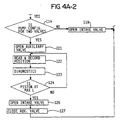
- Figure 4A shows a particular instruction sequence for controlling the metering pump of Figures 1A, 1B and 3 to deliver the determined flow rate. At the beginning of the program, the desired volumetric flow rate Q̇ is read into the
computer 28 instep 102. The desired flow rate is based on a stroke cycle time and volumetric discharge which occurs within the stroke cycle time. Assuming that the stroke cycle time is known and constant, using the earlier formula, the required effective stroke length L may be calculated instep 103. The calculation of the stroke length also depends upon having input certain information about the metering pump, such as piston diameter d, piston cycle rate T per the aforesaid equation. - Having thus calculated the desired stroke length for the piston, the intake valve is opened in
step 104. This intake valve permits the pumped media to enter thepumping chamber 15 of the embodiments of Figures 1A and 1B. The piston reciprocation begins instep 105 by energizing the motor drive to the piston. - The piston position is continually read and recorded in
step 107 by monitoring the output ofsensor 13. A diagnostics routine 108 is shown which is an optional subroutine to effectively diagnose any failure which might be indicated by the position sensor. This diagnostic routine 108 will be more specifically described with respect to Figure 4B. - In
decision block 109, the piston position is determined to be fully retracted at which point the beginning of the pumping of media from the pumpingchamber 15 begins. Theintake valve 21 is closed instep 110 to prohibit venting of the pumped media from pumpingchamber 15 to the pumpingmedia reservoir 25. The piston position during the subsequent advance of the piston is continuously monitored and recorded instep 111. A further diagnostic routine is shown in 112 which is optional, but described more particularly in Figure 4B. The diagnostic routine will assist in determining any failure which may occur such that position measurements instep 111 are not within a predicted range. - Once the piston reaches the calculated stroke length L,
decision block 113 will indicate it is time to end effective pumping from thechamber 15. In the event a single intake valve such as shown in Figures 1A and 1B is employed, as determined byblock 114, theinlet valve 21 is opened instep 118, thus effectively ending the pumping stroke for the piston 11. The remaining piston volume is displaced to themedia reservoir 25. - In
step 119, the desired flow rate is again read into the computer, and a new stroke length is calculated instep 120, identical to the calculation ofstep 103. In this way, in the event the operator at any point changes the desired flow rate Q̇, a new stroke length may be correspondingly calculated. - The flow chart of Figure 4A may also be applied to the system shown in Figure 3. As will be recalled, this system employs
separate valves decision block 114. Inblock 121, theauxiliary valve 30 is opened in order to vent the pumping chamber back to thereservoir 25. The position of the piston is continuously monitored instep 122 and anotherdiagnostic routine 123 is entered in the event the position of the piston is determined not to be in accordance with a predicted position. - Once the piston reaches its maximum stroke length L, determined by
block 124, theintake valve 21 is opened again instep 126 as the piston is fully advanced. At the same time, instep 127 theauxiliary valve 30 is closed, permitting additional pumped media to enter thepumping chamber 15 while the piston 11 retracts to its initial position. - A similar flow chart can be developed for the embodiment of Figure 5. As will be recalled, the embodiment of Figure 5 includes an
inlet valve 38 and avent valve 39. Control over these valves by the computer is accomplished with similar instruction sets which will be obvious in light of the previous flow chart (Figure 4A). - The flow chart outlined in Figure 4A could utilize diaphragm displacement to determine and/or verify volumetric discharge. As stated previously, the volume of the deflected shape of the diaphragm can be mathematically approximated. Therefore, given a desired volumetric displacement, a value for diaphragm deflection can be calculated. This is analogous to the calculation of L effective for the piston. The diaphragm position can then be monitored during pump discharge - in a manner similar to the way the piston is monitored - until it reaches the proper level of deflection. At this point, the appropriate volume of media will have been discharged.
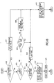
- Referring now to Figure 4B, the diagnostic routine which is entered at various stages of the programming shown in Figure 4A. The routine begins with
block 201. The first check made is whether or not the piston has changed position as evidenced by the output from thesensor 13. If the piston has changed position, the piston flag is set FALSE instep 202 and the drive flag is also set FALSE instep 203. The two false designations for the drive and piston flags indicate that these components are both operating properly. The current piston position is recorded instep 205 to be used in the next re-entrance to the diagnostics routine. The diagnostic program then exits to the main program in Figure 4A. - In the event there is no indication of a change in piston position, step 207 will be used to determine whether or not the motor is active. It is contemplated that a motor enable line will be provided by the
computer 28. If this enable line is not active,step 208 will determine whether or not the drive flag has been set true. If not, the drive flag will be set true instep 209, and an attempt made to start the motor instep 210. The ENABLE signal will be raised by the computer to try to restart the motor drive. - If the drive flag is set true, and the motor is determined not to be active in
step 207, the operator is notified of a failed motor drive instep 222. - Continuing in the diagnostic program, the position sensor output is checked in
decision block 212. The normal voltage potential is a non-zero value. If the output is equal to 0, the piston flag is checked to see whether it is true or false. In the event it is not true, the piston flag is set true before exiting viastep 205 to the main program. In the event the piston flag has been set true, the operator is notified instep 220 of a failed piston position sensor. - If the piston sensor output is not equal to 0 in
block 212, and the drive flag has previously been set true inblock 213, the operator is notified inblock 221 of a failed drive mechanism. If the drive flag has been set false inblock 213, the flag is set true in 214 before exiting viastep 205. - If the piston flag has been set true in
block 216, or the drive flag has been set true in 208 or 213, a failure condition has been determined and the pump is shut down in step 223. The operator is notified in steps 220-222 of the particular sensed failure. - Thus, the foregoing diagnostics will be used to determine whether there has been any piston motion. In the event there has not been, the fault condition is analyzed to determine whether a piston position sensor failure has occurred, there is a drive mechanism failure, or a motor failure.
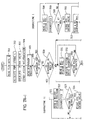
- Referring now to Figures 7A and 7B, there is shown a program routine for controlling the metering pump of Figure 6. The flow chart shown in Figures 7A and 7B describe the programming steps executed by
computer 28 for controlling the hydraulically balanced diaphragm metering pump. - There are shown programming steps for the
computer 28 in the embodiments shown in Figure 6. This embodiment is a hydraulically balanced diaphragm metering pump which accurately positions the diaphragm prior to beginning a pumping discharge stroke. In the embodiment shown in Figure 6, two proximity sensors are shown, 43 and 46, which detect whether or not the diaphragm is properly positioned to begin a discharge portion of the pump cycle. - The programming steps shown in Figure 7 include two branches, I and II. Each of these branches is used to position the diaphragm at pump start-up. The branch that is taken depends on whether it has been determined that the diaphragm is forward or rearward of its start position. As is clear from Figure 7A, two decision blocks 306 and 320 will make the determination as to whether or not the diaphragm is in its correct position. If not, the program will exit to the prepositioning appropriate subroutine shown in I and II.
- The beginning of the computer-executed sequence starts with a reading of the desired flow rate Q̇ in
step 301. From this signal, i.e., inputted data by the operator, a pump stroke L is determined which will generate the appropriate flow rate in accordance with the previous equations. The hydraulic intake valve is opened instep 303, corresponding to thevalve 38 shown in Figure 6. At this time, the piston reciprocation is started instep 304, while simultaneously reading the diaphragm position instep 305. The diaphragm position is determined from signals produced by proximity sensors 43 and 46. - If the diaphragm has been determined to be in the proper starting position, decision blocks 306 and 320 will transfer control to
programming step 331. At this time, the piston position is read from theposition sensor 13. Piston drive diagnostics are included instep 332 which were described previously with regard to Figure 4B. It should be noted that this is optional and the program can be configured to operate without the diagnostics subroutine of 332. -
Decision block 333 will determine whether or not the piston has been fully retracted. When the piston is in its fully retracted position, as noted from theposition sensor 13,valve 38 is closed to begin the start of the discharge portion of thestroke cycle step 334. The positions of the piston and diaphragm are continually read and diagnosed in steps 335-338, and when the piston reaches the calculated distance L for discharging the appropriate amount of pumped media as determined bydecision block 339 within the required time interval,decision block 340 will transfer control tosteps - Assuming that only a single valve is included in the intermediate reservoir supply,
step 341 will open the intake valve, thus venting theintermediate pressure chamber 18 into thereservoir 44. The piston position is continually read instep 342, and when the piston has been fully extended,decision block 344 will transfer control to step 345 which closes thehydraulic intake valve 38. - When two valves are employed in venting and supplying fluid to the intermediate chamber, such as is shown in Figure 5, it being appreciated that the embodiment of Figure 5 could also include two proximity sensors 43 and 46, the
decision block 340 will transfer control to step 349. The second valve is opened to permit venting of the intermediate chamber through the secondsuch valve 38 of Figure 5. The position of the piston is monitored instep 350 and when a fully extended position is obtained,decision block 352 will close the previously openedvalve 38 by executingstep 353. Diagnostics are included instep 351, similar to step 343, and are totally optional. - Once the required stroke length has been achieved in either a single or two valve configuration, the diaphragm and piston positions are noted in
steps step 358, the intake valve is opened instep 359. The current desired flow rate Q̇ is again read instep 360 and the pump parameters calculated instep 361 each time the program passes through a completed stroke. - The subroutine designated by I will position the diaphragm to a starting position when it has been found to be forward of its predetermined starting position. Step 308 and decision block 310 will continuously read the position of the piston and when it has reached its maximum extension, will close the hydraulic intake valve in
step 311. Step 312 and decision block 314 will monitor the diaphragm position as it retracts with the piston. Once the position of the diaphragm has been determined to be correct indecision block 314, due to the retraction of the piston which will exert a pressure on the diaphragm, pulling it towards its starting position, control will switch to step 317. In step 317, the hydraulic intake valve will be opened to stop movement of the diaphragm. - Control will proceed with
step 331. If the diaphragm is not at its starting position as determined inblock 314, block 315 will evaluate the piston position. If the piston is fully retracted, the hydraulic intake valve will be opened instep 316, permitting fluid to enter the intermediate chamber while the piston is extended to its furthest position. The program then recycles to step 308 until the diaphragm is properly positioned. - Subroutine II similarly operates to position the diaphragm to its correct starting position when it is found to be in back of its correct position. This requires continuously reading the position of the piston in
step 321 and determining whether or not the piston is fully retracted instep 323. When it has become fully retracted, the intake valve is closed instep 324. Measurements of the diaphragm position are made instep 325. Once the diaphragm is determined to be at its correct starting position, as determined byblock 327, the hydraulic intake valve is opened instep 330 and control can switch to step 331. When the piston becomes fully extended, and the diaphragm has not reached starting position, as determined byblock 328, the intake valve is opened instep 329 and the process recycles to 321 until the diaphragm has been correctly positioned. - Thus, there is shown one programming scheme which will permit the implementation of the embodiment shown in Figure 6, using a single valve, as well as a double valve configuration shown in Figure 5, when accompanied by a proximity sensor for positioning the diaphragm. The computer control over the start position for the diaphragm will make the accurate discharge of a predetermined quantity of pumped fluid more consistent over time. Additionally, the various diagnostic routines will aid in determining when the diaphragm pump has suffered a failure, and permits warning of the operator that the failure has occurred.
- The diagnostic routines are piston drive diagnostic routines and diaphragm diagnostic routines. The piston drive diagnostic routine is shown in Figure 4B and is incorporated throughout the execution of the program of Figures 7A and 7B.
- The diaphragm diagnostic routine of Figure 8 begins by detecting whether or not the diaphragm has changed position in
step 401. If it has, there is a diaphragm flag which is set FALSE instep 403. The routine then exits throughstep 411. - When the diaphragm has not been determined to have changed position, the sensor output signal from sensors 43 and 46 is checked in
step 404. In the event the sensor output is determined not to be 0, and the drive flag has not been set true as determined instep 405, the operator is warned of a diaphragm malfunction instep 406. Should the drive flag be set true in 405, the routine exits throughblock 411. The drive flag is set during the piston diagnostic routine, as previously explained regarding Figure 4B. - In the
event decision block 404 indicates that the output from sensors 43 and 46 is 0, and the diaphragm flag has been set to true instep 408, failure in the diaphragm position sensor is noted instep 412. This could be a failure of the sensor or the diaphragm itself. The pump is shut down instep 413 upon notification of the operator instep 412 of the failed component. Should the diaphragm flag be set false inblock 408, it is subsequently set true inblock 409. The routine then exits through 411. - Assuming the diaphragm diagnostics indicate no problem, the old diaphragm position value is set in
step 411 to the new value and the program continues as though no failure had occurred. The routine subsequently exits to the calling program. - The foregoing computer implementations are exemplary only of schemes which may be implemented to include diagnostic routines or to admit diagnostic routines. These embodiments will provide for distributed localized control over metering pumps which may be updated by an operator as convenient, and which will warn of malfunctions as they occur.
Claims (8)
- A metering pump wherein a reciprocating piston (11) pumps a metered quantity of fluid from a pumping chamber (15) based upon a stroke length of the piston, and wherein a computer (28) responsive to a signal from a sensor (13) sensing the stroke position of the piston (11) determines the volume of fluid being pumped and compares the computed volume with a desired volume, the computer (28) controlling means for inhibiting the pumping of fluid from the pumping chamber when the computed volume equals the desired volume, characterised in that the means for inhibiting the pumping of fluid from the pumping chamber (15) comprises electrically operated valve means (21, 30, 38) for venting either the pumping chamber (15) or a chamber (18) intermediate the piston (11) and the pumping chamber to a respective reservoir (25, 44).
- A metering pump according to claim 1 wherein the piston (11) displaces an intermediate fluid in the intermediate chamber (18) against a movable diaphragm (14, 21) in fluid communication with the pumping chamber (15).
- A metering pump according to claim 2 further comprising a second electrically operated valve means (39) connecting the reservoir (44) of intermediate fluid to the intermediate chamber (18), the fluid vented to the reservoir (44) being recirculated through the second valve means (39) to the intermediate chamber (18).
- A metering pump according to claim 2 or claim 3 further comprising a position sensor (43, 46) for sensing the relative position of the movable diaphragm (14, 21).
- A metering pump according to claim 4 wherein the diaphragm position sensor (43, 46) supplies a signal to the computer (28), and the computer monitors the diaphragm position.
- A metering pump according to claim 5 wherein the computer (28) determines a starting position for the diaphragm (14) from the diaphragm position sensor signal.
- A metering pump according to claim 6 wherein the computer (28) is programmed to return the diaphragm (14) to the starting position before commencing pumping of the fluid from the metering chamber.
- A metering pump according to any one of the preceding claims wherein the computer (28) is programmed with piston drive diagnostic routines and diaphragm diagnostic routines for detecting when a failure has occurred in the computer-controlled pump.
Applications Claiming Priority (3)
| Application Number | Priority Date | Filing Date | Title |
|---|---|---|---|
| US07/424,443 US5056036A (en) | 1989-10-20 | 1989-10-20 | Computer controlled metering pump |
| US424443 | 1989-10-20 | ||
| PCT/US1990/006054 WO1991006062A1 (en) | 1989-10-20 | 1990-10-22 | Computer controlled metering pump |
Publications (3)
| Publication Number | Publication Date |
|---|---|
| EP0496803A1 EP0496803A1 (en) | 1992-08-05 |
| EP0496803A4 EP0496803A4 (en) | 1993-08-04 |
| EP0496803B1 true EP0496803B1 (en) | 1997-06-04 |
Family
ID=23682652
Family Applications (1)
| Application Number | Title | Priority Date | Filing Date |
|---|---|---|---|
| EP90916125A Expired - Lifetime EP0496803B1 (en) | 1989-10-20 | 1990-10-22 | Computer controlled metering pump |
Country Status (7)
| Country | Link |
|---|---|
| US (1) | US5056036A (en) |
| EP (1) | EP0496803B1 (en) |
| JP (1) | JPH05508700A (en) |
| AT (1) | ATE154152T1 (en) |
| CA (1) | CA2066581C (en) |
| DE (1) | DE69030881T2 (en) |
| WO (1) | WO1991006062A1 (en) |
Families Citing this family (89)
| Publication number | Priority date | Publication date | Assignee | Title |
|---|---|---|---|---|
| US5249932A (en) * | 1991-10-07 | 1993-10-05 | Erik Van Bork | Apparatus for controlling diaphragm extension in a diaphragm metering pump |
| US5378122A (en) | 1993-02-16 | 1995-01-03 | Wilden Pump & Engineering Co. | Air driven diaphragm pump |
| FR2706857B1 (en) * | 1993-06-25 | 1995-10-27 | Dussau Distribution Sarl | |
| US5526685A (en) * | 1995-01-17 | 1996-06-18 | Graseby Andersen Inc. | Fluid flow rate measuring and controlling apparatus and method for using same |
| JP3371687B2 (en) * | 1996-06-11 | 2003-01-27 | 株式会社スリーボンド | Dispensing method |
| US5751599A (en) * | 1996-07-10 | 1998-05-12 | Bortnik; Michael | Probeless microprocessor based controller for open recirculating evaporative cooling systems |
| US5975854A (en) * | 1997-05-09 | 1999-11-02 | Copeland Corporation | Compressor with protection module |
| US6017200A (en) * | 1997-08-12 | 2000-01-25 | Science Applications International Corporation | Integrated pumping and/or energy recovery system |
| DE19742632A1 (en) * | 1997-09-26 | 1999-04-08 | Fresenius Medical Care De Gmbh | Pumping and dosing device |
| US6109881A (en) * | 1998-01-09 | 2000-08-29 | Snodgrass; Ocie T. | Gas driven pump for the dispensing and filtering of process fluid |
| DE19826610A1 (en) | 1998-06-16 | 1999-12-23 | Bran & Luebbe | Diaphragm pump and device for controlling the same |
| US6585933B1 (en) | 1999-05-03 | 2003-07-01 | Betzdearborn, Inc. | Method and composition for inhibiting corrosion in aqueous systems |
| US6280147B1 (en) | 1998-10-13 | 2001-08-28 | Liquid Metronics Incorporated | Apparatus for adjusting the stroke length of a pump element |
| US6174136B1 (en) | 1998-10-13 | 2001-01-16 | Liquid Metronics Incorporated | Pump control and method of operating same |
| US6505475B1 (en) | 1999-08-20 | 2003-01-14 | Hudson Technologies Inc. | Method and apparatus for measuring and improving efficiency in refrigeration systems |
| US6264432B1 (en) * | 1999-09-01 | 2001-07-24 | Liquid Metronics Incorporated | Method and apparatus for controlling a pump |
| US6302654B1 (en) * | 2000-02-29 | 2001-10-16 | Copeland Corporation | Compressor with control and protection system |
| US7047753B2 (en) * | 2000-03-14 | 2006-05-23 | Hussmann Corporation | Refrigeration system and method of operating the same |
| US6973794B2 (en) | 2000-03-14 | 2005-12-13 | Hussmann Corporation | Refrigeration system and method of operating the same |
| US6647735B2 (en) | 2000-03-14 | 2003-11-18 | Hussmann Corporation | Distributed intelligence control for commercial refrigeration |
| US7000422B2 (en) | 2000-03-14 | 2006-02-21 | Hussmann Corporation | Refrigeration system and method of configuring the same |
| US6332327B1 (en) | 2000-03-14 | 2001-12-25 | Hussmann Corporation | Distributed intelligence control for commercial refrigeration |
| US6999996B2 (en) * | 2000-03-14 | 2006-02-14 | Hussmann Corporation | Communication network and method of communicating data on the same |
| US6393338B1 (en) * | 2000-03-17 | 2002-05-21 | Tadeusz Kemnitz | Apparatus and control method for accurate rotary peristaltic pump filling |
| US6350110B1 (en) * | 2000-03-31 | 2002-02-26 | B&G International | Multiport metering pump |
| US6668240B2 (en) | 2001-05-03 | 2003-12-23 | Emerson Retail Services Inc. | Food quality and safety model for refrigerated food |
| US6892546B2 (en) | 2001-05-03 | 2005-05-17 | Emerson Retail Services, Inc. | System for remote refrigeration monitoring and diagnostics |
| US6640556B2 (en) | 2001-09-19 | 2003-11-04 | Westport Research Inc. | Method and apparatus for pumping a cryogenic fluid from a storage tank |
| US6625519B2 (en) | 2001-10-01 | 2003-09-23 | Veeder-Root Company Inc. | Pump controller for submersible turbine pumps |
| US7204679B2 (en) * | 2002-09-30 | 2007-04-17 | Emerson Electric Co. | Flow control system |
| JP4187500B2 (en) * | 2002-10-25 | 2008-11-26 | アルパイン株式会社 | Message processing apparatus and system |
| US6889173B2 (en) | 2002-10-31 | 2005-05-03 | Emerson Retail Services Inc. | System for monitoring optimal equipment operating parameters |
| US7094353B2 (en) * | 2002-11-04 | 2006-08-22 | Arch Chemicals, Inc. | Method of water treatment |
| US8463441B2 (en) | 2002-12-09 | 2013-06-11 | Hudson Technologies, Inc. | Method and apparatus for optimizing refrigeration systems |
| WO2005022049A2 (en) | 2003-08-25 | 2005-03-10 | Computer Process Controls, Inc. | Refrigeration control system |
| US6946968B1 (en) | 2003-09-24 | 2005-09-20 | Johnson Clifford C | Hydraulic stroke measuring system |
| CN100368199C (en) * | 2004-02-12 | 2008-02-13 | 佳能株式会社 | Liquid applying apparatus and ink jet printing apparatus |
| US7412842B2 (en) | 2004-04-27 | 2008-08-19 | Emerson Climate Technologies, Inc. | Compressor diagnostic and protection system |
| US7275377B2 (en) | 2004-08-11 | 2007-10-02 | Lawrence Kates | Method and apparatus for monitoring refrigerant-cycle systems |
| WO2006091521A2 (en) | 2005-02-21 | 2006-08-31 | Computer Process Controls, Inc. | Enterprise control and monitoring system |
| DE202005013090U1 (en) * | 2005-08-19 | 2007-01-04 | Prominent Dosiertechnik Gmbh | Motor e.g. asynchronous motor, dosing pump for dosing e.g. oil, has position sensor providing motion sequence of displacement organ so that electronic controlling of pump responds to operating conditions of dosing circle and dosing pump |
| DE102005039237A1 (en) * | 2005-08-19 | 2007-02-22 | Prominent Dosiertechnik Gmbh | motor-driven metering |
| US7594407B2 (en) | 2005-10-21 | 2009-09-29 | Emerson Climate Technologies, Inc. | Monitoring refrigerant in a refrigeration system |
| US7596959B2 (en) | 2005-10-21 | 2009-10-06 | Emerson Retail Services, Inc. | Monitoring compressor performance in a refrigeration system |
| US7752854B2 (en) | 2005-10-21 | 2010-07-13 | Emerson Retail Services, Inc. | Monitoring a condenser in a refrigeration system |
| US7752853B2 (en) | 2005-10-21 | 2010-07-13 | Emerson Retail Services, Inc. | Monitoring refrigerant in a refrigeration system |
| US7665315B2 (en) | 2005-10-21 | 2010-02-23 | Emerson Retail Services, Inc. | Proofing a refrigeration system operating state |
| SE529328C2 (en) | 2005-11-15 | 2007-07-10 | Johan Stenberg | Control system and method for controlling electromagnetically driven pumps |
| US8590325B2 (en) | 2006-07-19 | 2013-11-26 | Emerson Climate Technologies, Inc. | Protection and diagnostic module for a refrigeration system |
| US20080216494A1 (en) | 2006-09-07 | 2008-09-11 | Pham Hung M | Compressor data module |
| CN101245770B (en) * | 2007-02-17 | 2012-05-30 | 卓越剂量技术有限公司 | Electromotor driven metering pump |
| US20090037142A1 (en) | 2007-07-30 | 2009-02-05 | Lawrence Kates | Portable method and apparatus for monitoring refrigerant-cycle systems |
| US20090041588A1 (en) * | 2007-08-08 | 2009-02-12 | Halliburton Energy Services, Inc. | Active valve system for positive displacement pump |
| US8152476B2 (en) * | 2007-08-24 | 2012-04-10 | Toyo Pumps North America Corp. | Positive displacement pump with a working fluid and linear motor control |
| US8393169B2 (en) | 2007-09-19 | 2013-03-12 | Emerson Climate Technologies, Inc. | Refrigeration monitoring system and method |
| US9140728B2 (en) | 2007-11-02 | 2015-09-22 | Emerson Climate Technologies, Inc. | Compressor sensor module |
| US8160827B2 (en) | 2007-11-02 | 2012-04-17 | Emerson Climate Technologies, Inc. | Compressor sensor module |
| US8185237B2 (en) * | 2007-12-28 | 2012-05-22 | Malema Engineering Corporation | Dispense verification meters |
| NO330021B1 (en) * | 2009-02-11 | 2011-02-07 | Statoil Asa | Installations for storage and supply of compressed gas |
| BRPI1014993A8 (en) | 2009-05-29 | 2016-10-18 | Emerson Retail Services Inc | system and method for monitoring and evaluating equipment operating parameter modifications |
| US8565925B2 (en) * | 2009-09-29 | 2013-10-22 | Virid Services Llc | System and method for injecting a fluid additive into a fluid dispensation system |
| NL1037427C2 (en) * | 2009-10-30 | 2011-05-03 | Lely Patent Nv | MILK PUMP DEVICE AND METHOD FOR MOVING A QUANTITY OF MILK. |
| US9850889B2 (en) * | 2010-02-02 | 2017-12-26 | Dajustco Ip Holdings Inc. | Hydraulic fluid control system for a diaphragm pump |
| EP2362100B2 (en) * | 2010-02-18 | 2020-07-08 | Grundfos Management A/S | Metering pump aggregate and method for controlling same |
| FR2965864B1 (en) * | 2010-10-08 | 2012-12-14 | Dosatron International | LIQUID DOSING PUMP, AND DEVICE FOR DETECTING PRESSURE VARIATION FOR SUCH A PUMP. |
| EP2661412A4 (en) * | 2011-01-05 | 2014-10-08 | Noam Levine | A fluid flow meter |
| CA2934860C (en) | 2011-02-28 | 2018-07-31 | Emerson Electric Co. | Residential solutions hvac monitoring and diagnosis |
| US8459195B2 (en) | 2011-04-28 | 2013-06-11 | Michael H. IRVING | Self load sensing circuit board controller diaphragm pump |
| US8434697B1 (en) * | 2011-05-12 | 2013-05-07 | Peter Olt | Autonomous system for injecting additives into irrigation water |
| ITCO20110071A1 (en) * | 2011-12-22 | 2013-06-23 | Nuovo Pignone Spa | ALTERNATIVE COMPRESSORS HAVING TIMED VALVES AND RELATED METHODS |
| US8964338B2 (en) | 2012-01-11 | 2015-02-24 | Emerson Climate Technologies, Inc. | System and method for compressor motor protection |
| CN102661766B (en) * | 2012-05-16 | 2013-06-12 | 长沙伟诺机电有限公司 | Asphalts small flow metering device |
| US8687180B2 (en) * | 2012-06-07 | 2014-04-01 | Molecular Devices, Llc | System, method, and device for determining a focal position of an objective in a microscopy imaging system |
| US9480177B2 (en) | 2012-07-27 | 2016-10-25 | Emerson Climate Technologies, Inc. | Compressor protection module |
| US9310439B2 (en) | 2012-09-25 | 2016-04-12 | Emerson Climate Technologies, Inc. | Compressor having a control and diagnostic module |
| CA2904734C (en) | 2013-03-15 | 2018-01-02 | Emerson Electric Co. | Hvac system remote monitoring and diagnosis |
| US9803902B2 (en) | 2013-03-15 | 2017-10-31 | Emerson Climate Technologies, Inc. | System for refrigerant charge verification using two condenser coil temperatures |
| US9551504B2 (en) | 2013-03-15 | 2017-01-24 | Emerson Electric Co. | HVAC system remote monitoring and diagnosis |
| US9765979B2 (en) | 2013-04-05 | 2017-09-19 | Emerson Climate Technologies, Inc. | Heat-pump system with refrigerant charge diagnostics |
| FR3005647B1 (en) * | 2013-05-17 | 2015-09-04 | Cirmeca | DEVICE AND METHOD FOR DETERMINING PRODUCTS AND FILLING CONTAINERS WITH SAID PRODUCTS |
| CN103244390B (en) * | 2013-05-20 | 2015-06-24 | 贝恩医疗设备(广州)有限公司 | Metering pump |
| US9605664B2 (en) * | 2014-01-07 | 2017-03-28 | Ingersoll-Rand Company | Pneumatic piston pump metering and dispense control |
| US10954931B2 (en) * | 2014-12-12 | 2021-03-23 | Dh Technologies Development Pte. Ltd. | Linear displacement pump with position sensing and related systems and methods |
| ITUB20160404A1 (en) | 2016-01-26 | 2017-07-26 | Global Service Design Ltd Uk Company Number 07411425 | APPARATUS FOR THE CONTROLLED DISTRIBUTION OF A FLUID FROM A CONTAINER AND ITS RELATION METHOD |
| DE102016117357A1 (en) * | 2016-09-15 | 2018-03-15 | Prominent Gmbh | Method for operating metering devices |
| WO2018093385A1 (en) * | 2016-11-21 | 2018-05-24 | Halliburton Energy Services, Inc. | Cylinder pump systems and methods for pumping and measuring fluids |
| US20180372083A1 (en) * | 2017-06-22 | 2018-12-27 | Wanner Engineering, Inc. | Hydraulic diaphragm control |
| AU2018204487B1 (en) * | 2017-11-10 | 2019-05-30 | Quantum Servo Pumping Technologies Pty Ltd | Pumping systems |
| CA3200839A1 (en) * | 2020-11-09 | 2022-05-12 | Pdc Machines Inc. | Active oil injection system for a diaphragm compressor |
Family Cites Families (15)
| Publication number | Priority date | Publication date | Assignee | Title |
|---|---|---|---|---|
| DE1084486B (en) * | 1954-04-15 | 1960-06-30 | Kontak Mfg Company Ltd | Liquid metering pump |
| US3227314A (en) * | 1964-03-03 | 1966-01-04 | Porter Lancastrian Ltd | Delivering of measured quantities of pressurised liquids |
| US3756456A (en) * | 1972-05-22 | 1973-09-04 | Graco Inc | Apparatus and method for a metering system |
| US3913314A (en) * | 1972-06-09 | 1975-10-21 | Westinghouse Electric Corp | System and method for operating a gas turbine electric power plant with bypass flow fueling operation to provide improved reliability and extended apparatus life |
| US4241602A (en) * | 1979-04-20 | 1980-12-30 | Seismograph Service Corporation | Rheometer |
| DE2933327A1 (en) * | 1979-08-17 | 1981-03-26 | Bayer Ag, 51373 Leverkusen | METHOD AND DEVICE FOR PRODUCING A FLOWABLE REACTION MIXTURE MAKING SOLID OR FOAM |
| US4315523A (en) * | 1980-03-06 | 1982-02-16 | American Flow Systems, Inc. | Electronically controlled flow meter and flow control system |
| US4474309A (en) * | 1981-10-22 | 1984-10-02 | Oximetrix, Inc. | Stepping motor control procedure for achieving variable rate, quasi-continuous fluid infusion |
| DE3203087A1 (en) * | 1982-01-30 | 1983-08-04 | Gebrüder Sucker, 4050 Mönchengladbach | METHOD AND DEVICE FOR COATING OR IMRAEGNING A SUBSTRATE GUIDED IN A TRAIN |
| DE3204050C1 (en) * | 1982-02-06 | 1983-07-21 | Chemie Und Filter Gmbh, Verfahrenstechnik Kg, 6900 Heidelberg | Electromagnetically operated axial piston pump, especially diaphragm pump |
| US4715786A (en) * | 1984-12-14 | 1987-12-29 | Cole-Parmer Instrument Company | Control method and apparatus for peristaltic fluid pump |
| US4796782A (en) * | 1985-10-30 | 1989-01-10 | Automation, Inc. | Ink monitor system |
| US4723976A (en) * | 1986-07-30 | 1988-02-09 | Owens-Illinois Television Products Inc. | Method and apparatus for pressing glass cathode ray tube faceplates |
| DE3706338A1 (en) * | 1987-02-27 | 1988-09-08 | Wagner Gmbh J | DIAPHRAGM PUMP DEVICE |
| US4897797A (en) * | 1988-04-25 | 1990-01-30 | Betz Laboratories, Inc. | Proportional chemical feeding system |
-
1989
- 1989-10-20 US US07/424,443 patent/US5056036A/en not_active Expired - Lifetime
-
1990
- 1990-10-22 CA CA002066581A patent/CA2066581C/en not_active Expired - Fee Related
- 1990-10-22 JP JP90515053A patent/JPH05508700A/en active Pending
- 1990-10-22 AT AT90916125T patent/ATE154152T1/en not_active IP Right Cessation
- 1990-10-22 DE DE69030881T patent/DE69030881T2/en not_active Expired - Fee Related
- 1990-10-22 EP EP90916125A patent/EP0496803B1/en not_active Expired - Lifetime
- 1990-10-22 WO PCT/US1990/006054 patent/WO1991006062A1/en active IP Right Grant
Also Published As
| Publication number | Publication date |
|---|---|
| EP0496803A4 (en) | 1993-08-04 |
| DE69030881D1 (en) | 1997-07-10 |
| CA2066581C (en) | 2000-10-10 |
| ATE154152T1 (en) | 1997-06-15 |
| CA2066581A1 (en) | 1991-04-21 |
| DE69030881T2 (en) | 1997-09-18 |
| WO1991006062A1 (en) | 1991-05-02 |
| JPH05508700A (en) | 1993-12-02 |
| US5056036A (en) | 1991-10-08 |
| EP0496803A1 (en) | 1992-08-05 |
Similar Documents
| Publication | Publication Date | Title |
|---|---|---|
| EP0496803B1 (en) | Computer controlled metering pump | |
| JP4738171B2 (en) | Method for identifying the operating state of a medical pump | |
| RU2086806C1 (en) | System and method for control of liquid diaphragm pump | |
| EP1508736B1 (en) | Method for diagnosing a cyclic system | |
| RU2106561C1 (en) | Method and device for check of medium-actuated fittings | |
| EP3187735B1 (en) | Pump system as well as a method for determining the flow in a pump system | |
| US5292306A (en) | Method of detecting occlusions in a solution pumping system | |
| KR100430170B1 (en) | Method and apparatus for controlling a pump of an electrohydraulic braking system | |
| EP0281294A2 (en) | Fluid delivery system with deficit flow compensation | |
| EP2795266B1 (en) | Method for dosing a fluid | |
| US5319572A (en) | Electrohydraulic fluid monitor system | |
| EP0619874A1 (en) | Pump station flowmeter with high frequency detector | |
| CN103619480A (en) | Process for detecting anomalies during the filling of a liquid metering device and liquid metering device | |
| US20230374987A1 (en) | Method for Ascertaining Leaks of a Displacement Pump | |
| US4649734A (en) | Apparatus and method for calibrating a flow meter | |
| JP3317778B2 (en) | Automatic measuring method of gas pressure of accumulator | |
| JPS63106382A (en) | Liquid feeding pump | |
| KR101998395B1 (en) | High speed high capacity flow measuring device for repeated pressurized testing of ultra high pressure container | |
| NL1004028C2 (en) | Method for determining the amount of undissolved gas in a hydraulic system. | |
| JP2004212128A (en) | Abnormality monitoring method of hydraulic device | |
| US11365727B2 (en) | Failure diagnosing device, pump unit including same, and failure diagnosing method | |
| US5404920A (en) | Automated fluid charging apparatus | |
| EP3579994B1 (en) | Die-casting machine with a valve diagnosis system | |
| US20200032788A1 (en) | Piston Pump And Method For Determining Volume Delivered By Piston Pump | |
| JP3183663B2 (en) | Automatic yeast addition device |
Legal Events
| Date | Code | Title | Description |
|---|---|---|---|
| PUAI | Public reference made under article 153(3) epc to a published international application that has entered the european phase |
Free format text: ORIGINAL CODE: 0009012 |
|
| 17P | Request for examination filed |
Effective date: 19920331 |
|
| AK | Designated contracting states |
Kind code of ref document: A1 Designated state(s): AT BE CH DE DK ES FR GB GR IT LI LU NL SE |
|
| A4 | Supplementary search report drawn up and despatched |
Effective date: 19930614 |
|
| AK | Designated contracting states |
Kind code of ref document: A4 Designated state(s): AT BE CH DE DK ES FR GB GR IT LI LU NL SE |
|
| 17Q | First examination report despatched |
Effective date: 19960109 |
|
| GRAG | Despatch of communication of intention to grant |
Free format text: ORIGINAL CODE: EPIDOS AGRA |
|
| GRAH | Despatch of communication of intention to grant a patent |
Free format text: ORIGINAL CODE: EPIDOS IGRA |
|
| GRAH | Despatch of communication of intention to grant a patent |
Free format text: ORIGINAL CODE: EPIDOS IGRA |
|
| GRAA | (expected) grant |
Free format text: ORIGINAL CODE: 0009210 |
|
| AK | Designated contracting states |
Kind code of ref document: B1 Designated state(s): AT BE CH DE DK ES FR GB GR IT LI LU NL SE |
|
| PG25 | Lapsed in a contracting state [announced via postgrant information from national office to epo] |
Ref country code: IT Free format text: LAPSE BECAUSE OF FAILURE TO SUBMIT A TRANSLATION OF THE DESCRIPTION OR TO PAY THE FEE WITHIN THE PRESCRIBED TIME-LIMIT;WARNING: LAPSES OF ITALIAN PATENTS WITH EFFECTIVE DATE BEFORE 2007 MAY HAVE OCCURRED AT ANY TIME BEFORE 2007. THE CORRECT EFFECTIVE DATE MAY BE DIFFERENT FROM THE ONE RECORDED. Effective date: 19970604 Ref country code: GR Free format text: LAPSE BECAUSE OF FAILURE TO SUBMIT A TRANSLATION OF THE DESCRIPTION OR TO PAY THE FEE WITHIN THE PRESCRIBED TIME-LIMIT Effective date: 19970604 Ref country code: NL Free format text: LAPSE BECAUSE OF FAILURE TO SUBMIT A TRANSLATION OF THE DESCRIPTION OR TO PAY THE FEE WITHIN THE PRESCRIBED TIME-LIMIT Effective date: 19970604 Ref country code: LI Effective date: 19970604 Ref country code: CH Effective date: 19970604 Ref country code: BE Effective date: 19970604 Ref country code: ES Free format text: THE PATENT HAS BEEN ANNULLED BY A DECISION OF A NATIONAL AUTHORITY Effective date: 19970604 Ref country code: AT Effective date: 19970604 Ref country code: DK Effective date: 19970604 |
|
| REF | Corresponds to: |
Ref document number: 154152 Country of ref document: AT Date of ref document: 19970615 Kind code of ref document: T |
|
| REG | Reference to a national code |
Ref country code: CH Ref legal event code: EP |
|
| REF | Corresponds to: |
Ref document number: 69030881 Country of ref document: DE Date of ref document: 19970710 |
|
| PG25 | Lapsed in a contracting state [announced via postgrant information from national office to epo] |
Ref country code: SE Effective date: 19970904 |
|
| ET | Fr: translation filed | ||
| PG25 | Lapsed in a contracting state [announced via postgrant information from national office to epo] |
Ref country code: LU Free format text: LAPSE BECAUSE OF NON-PAYMENT OF DUE FEES Effective date: 19971022 |
|
| NLV1 | Nl: lapsed or annulled due to failure to fulfill the requirements of art. 29p and 29m of the patents act | ||
| REG | Reference to a national code |
Ref country code: CH Ref legal event code: PL |
|
| PLBE | No opposition filed within time limit |
Free format text: ORIGINAL CODE: 0009261 |
|
| STAA | Information on the status of an ep patent application or granted ep patent |
Free format text: STATUS: NO OPPOSITION FILED WITHIN TIME LIMIT |
|
| 26N | No opposition filed | ||
| REG | Reference to a national code |
Ref country code: GB Ref legal event code: IF02 |
|
| PGFP | Annual fee paid to national office [announced via postgrant information from national office to epo] |
Ref country code: FR Payment date: 20020916 Year of fee payment: 13 |
|
| PGFP | Annual fee paid to national office [announced via postgrant information from national office to epo] |
Ref country code: DE Payment date: 20020918 Year of fee payment: 13 |
|
| PGFP | Annual fee paid to national office [announced via postgrant information from national office to epo] |
Ref country code: GB Payment date: 20021007 Year of fee payment: 13 |
|
| PG25 | Lapsed in a contracting state [announced via postgrant information from national office to epo] |
Ref country code: GB Free format text: LAPSE BECAUSE OF NON-PAYMENT OF DUE FEES Effective date: 20031022 |
|
| PG25 | Lapsed in a contracting state [announced via postgrant information from national office to epo] |
Ref country code: DE Free format text: LAPSE BECAUSE OF NON-PAYMENT OF DUE FEES Effective date: 20040501 |
|
| GBPC | Gb: european patent ceased through non-payment of renewal fee |
Effective date: 20031022 |
|
| PG25 | Lapsed in a contracting state [announced via postgrant information from national office to epo] |
Ref country code: FR Free format text: LAPSE BECAUSE OF NON-PAYMENT OF DUE FEES Effective date: 20040630 |
|
| REG | Reference to a national code |
Ref country code: FR Ref legal event code: ST |