EP0496633B1 - Microwave sterilizer for sealed containers - Google Patents
Microwave sterilizer for sealed containers Download PDFInfo
- Publication number
- EP0496633B1 EP0496633B1 EP92300610A EP92300610A EP0496633B1 EP 0496633 B1 EP0496633 B1 EP 0496633B1 EP 92300610 A EP92300610 A EP 92300610A EP 92300610 A EP92300610 A EP 92300610A EP 0496633 B1 EP0496633 B1 EP 0496633B1
- Authority
- EP
- European Patent Office
- Prior art keywords
- microwave
- oven
- ampoules
- sealed containers
- microwave oven
- Prior art date
- Legal status (The legal status is an assumption and is not a legal conclusion. Google has not performed a legal analysis and makes no representation as to the accuracy of the status listed.)
- Expired - Lifetime
Links
Images




Classifications
-
- A—HUMAN NECESSITIES
- A23—FOODS OR FOODSTUFFS; TREATMENT THEREOF, NOT COVERED BY OTHER CLASSES
- A23B—PRESERVATION OF FOODS, FOODSTUFFS OR NON-ALCOHOLIC BEVERAGES; CHEMICAL RIPENING OF FRUIT OR VEGETABLES
- A23B2/00—Preservation of foods or foodstuffs, in general
- A23B2/05—Preservation of foods or foodstuffs, in general by heating using irradiation or electric treatment
- A23B2/08—Preservation of foods or foodstuffs, in general by heating using irradiation or electric treatment using microwaves or dielectric heating
-
- A—HUMAN NECESSITIES
- A61—MEDICAL OR VETERINARY SCIENCE; HYGIENE
- A61L—METHODS OR APPARATUS FOR STERILISING MATERIALS OR OBJECTS IN GENERAL; DISINFECTION, STERILISATION OR DEODORISATION OF AIR; CHEMICAL ASPECTS OF BANDAGES, DRESSINGS, ABSORBENT PADS OR SURGICAL ARTICLES; MATERIALS FOR BANDAGES, DRESSINGS, ABSORBENT PADS OR SURGICAL ARTICLES
- A61L2/00—Disinfection or sterilisation of materials or objects, in general; Accessories therefor
- A61L2/02—Disinfection or sterilisation of materials or objects, in general; Accessories therefor using physical processes
- A61L2/08—Radiation
- A61L2/12—Microwaves
-
- B—PERFORMING OPERATIONS; TRANSPORTING
- B65—CONVEYING; PACKING; STORING; HANDLING THIN OR FILAMENTARY MATERIAL
- B65B—MACHINES, APPARATUS OR DEVICES FOR, OR METHODS OF, PACKAGING ARTICLES OR MATERIALS; UNPACKING
- B65B55/00—Preserving, protecting or purifying packages or package contents in association with packaging
- B65B55/02—Sterilising, e.g. of complete packages
- B65B55/12—Sterilising contents prior to, or during, packaging
- B65B55/16—Sterilising contents prior to, or during, packaging by irradiation
-
- H—ELECTRICITY
- H05—ELECTRIC TECHNIQUES NOT OTHERWISE PROVIDED FOR
- H05B—ELECTRIC HEATING; ELECTRIC LIGHT SOURCES NOT OTHERWISE PROVIDED FOR; CIRCUIT ARRANGEMENTS FOR ELECTRIC LIGHT SOURCES, IN GENERAL
- H05B6/00—Heating by electric, magnetic or electromagnetic fields
- H05B6/64—Heating using microwaves
- H05B6/78—Arrangements for continuous movement of material
-
- H—ELECTRICITY
- H05—ELECTRIC TECHNIQUES NOT OTHERWISE PROVIDED FOR
- H05B—ELECTRIC HEATING; ELECTRIC LIGHT SOURCES NOT OTHERWISE PROVIDED FOR; CIRCUIT ARRANGEMENTS FOR ELECTRIC LIGHT SOURCES, IN GENERAL
- H05B2206/00—Aspects relating to heating by electric, magnetic, or electromagnetic fields covered by group H05B6/00
- H05B2206/04—Heating using microwaves
- H05B2206/045—Microwave disinfection, sterilization, destruction of waste...
Definitions
- This invention relates to an apparatus using microwaves to heat-sterilize sealed containers such as ampoules filled with medical fluid and particularly to a microwave oven of coaxial tube type for such a purpose.
- the sealed containers for example, an ampoule filled with medical fluid such as injection medicine is conventionally subjected to a sterilizing treatment during its manufacturing process.
- the means utilizing the microwave is well known, for example, from Japanese Patent Application Disclosure Gazette No. 1973-59976 entitled "Method and apparatus for sterilization of medical fluid contained within ampoule", Japanese Patent Application Disclosure Gazette No. 1973-104381 entitled “Method and apparatus for sterilization of ampoule filled with liquid” and Japanese Patent Application Disclosure Gazette No. 1975-38985 entitled "Sterilizer for ampoule filled with liquid”.
- the microwave heater of oven type is also well known, for example, from U.S. Patent No. 4,687,895.
- the conventional heating means utilizing microwaves has been inconvenient in that the microwaves can not be efficiently absorbed by the sealed container and, to compensate this, it has been necessary to increase output of the microwave oscillator.
- the well known heating means utilizing microwaves has been disadvantageous also in that a sealed container of large volume can not be adequately sterilized. More specifically, most of such conventional apparatuses have been provided with a single microwave radiation oven and, therefore, the output of the microwave oscillator for this single oven has had to be increased to heat a sealed container of large volume. As a result, an extremely intense microwave energy has been concentrated onto the sealed container passing by the oscillator and there has been an anxiety that the temperature of medical fluid could not be controlled.
- the intense microwave energy is absorbed by the medical fluid contained within the sealed container, leading to a sudden rise of the temperature thereof, and it becomes difficult to control the temperature to a desired level.
- There have been further problems such as rupture of the container due to a sudden pressure rise within the container and damage of the container due to electric short caused by a high electrolytic intensity of the microwave between the sealed container and the medical fluid contained therewithin.
- EP-A-0401775 discloses an improved apparatus for heating ampoules.
- the apparatus includes an irradiator furnace through which microwaves are propagated in the opposite direction to the passage of ampoules. Microwaves are propagated through the furnace using a square waveguide. As the ampoules pass through the furnace, they are lifted about half-way along the furnace. In this way, the heating of the furnace is initially directed to an upper part of the ampoule, which is then lifted, after which the heating is directed to a lower part of the ampoule. In this way, the ampoule is more generally heated than is the case where the heat is always directed to the bottom of the ampoule.
- GB-A-1256339 also shows heating using a waveguide type microwave oven.
- the article to be heated is an edge of a sheet of material, which is passed between two opposed ridges.
- the ridges function to intensify the microwaves.
- the ridges vary in height along the length of the oven, and are shortest at the inlet end from which the microwaves are propagated. In this way, the maximum intensification due to the ridges occurs at the outlet end where the microwave power is reduced, thereby giving constant radiation along the length of the oven.
- a sterilizer for sterilizing sealed containers using microwave radiation comprising a microwave oven, in which the degree of coupling between the microwave radiation and the contents of the sealed containers decreases from the inlet side to the outlet side of the microwave oven, and the microwaves propagate from the outlet side to the inlet side of the microwave oven, characterised in that the microwave oven is of the co-axial tube type, having an inner conductor embedded in it, and in that the required degree of coupling is achieved by spacing the inner conductor further from the base of the sealed containers at the outlet end than at the inlet end.
- An advantage of the present invention is that the microwave radiation an absorption efficiency may be appropriately varied from an inlet side toward an outlet side of the microwave irradiation oven.
- the dose of microwave irradiation may be kept substantially constant and a temperature may rise at a constant rate to achieve a substantially even sterilization occurring without a sudden rise of the temperature.
- the technical measures allow the microwave to be efficiently absorbed by the bottom of the sealed container and cause a convection within the sealed container, thus reducing a temperature difference between upper and lower portions of the medical fluid so that said medical fluid may be evenly and adequately sterilized with a relatively low output of the microwave oscillator.
- the dose of microwave irradiation is kept constant and allows the temperature to rise at a constant ratio.
- Formation of a groove in the rail to support the bottom of the sealed container allows the sealed container to be stably conveyed, on one hand, and facilitates maintenance of the equipment, on the other hand, because, even if the glass container is broken during its conveyance, operation of removing pieces of the broken glass container will be easily done.
- the content of a sealed container can be sterilized without breakage thereof by irradiating the sealed container with relatively feeble microwave instead of concentrated intense microwave.
- Such technical measure eliminates anxieties that the sealed container might be concentrally irradiated with unacceptably intense microwave and the container might be broken due to such intense microwave, because the content of the sealed container is stepwise heated through two or more serially connected microwave ovens. Additionally, such arrangement allows the sterilizer to be made compact.
- the thickness variation of the rail from the inlet side toward the outlet side of the oven allows the oven's depth to be kept constant and facilitates connection of two or more ovens.
- Fig. 1 and Fig. 2 are perspective and plan views, respectively, of the sterilizer of the invention.
- a hopper 1 is equipped with a conveyor 3 used to supply ampoules a to a screw 2.
- a mechanism 4 assures that the ampoules a can be reliably supplied even when they would not be properly engaged with the screw 2.
- a correspondingly elliptical rail 7 as shown by Fig. 3 is laid. Top of the rail 7 has a cross-section laterally widened as seen in Fig. 4.
- the bucket 5 which is movable on the rail 7 is of a configuration as shown by Fig. 5 through 7. More specifically, a forward end of a bucket arm 8 is formed with a pair of recesses 9 adapted to hold the ampoules a and a base of said arm 8 is provided on its underside with a pair of members 10 each carrying a pair of rollers 11 on its longitudinally opposite ends. Said members 10 are pivotally supported on shafts 12, respectively, projecting downward from the underside of said bucket arm 8. The rollers 11 are engaged with the rail 7 from both sides so that the bucket arm 8 may smoothly move along the rail 7.
- the base of the bucket arm 8 carries on its top a disc 13 is centrally provided with a projection 14.
- the buckets 5 are mounted on the rail 7 so as to be arranged in an elliptical array along the rail 7 with said rollers 11 being in engagement with the rail 7 from both sides as shown by Fig. 7 and the discs 13 of the adjacent buckets 5 being in contact with each other as shown by Fig. 2.
- Rotation of sprockets 15, 16 provided on laterally opposite sides of the sterilizer causes the buckets 5 of which the central projections 14 on the discs 13 engaged with circumferential grooves 17, 18 of the respective sprockets 15, 16 to be moved so that, as the buckets 5 successively pass the sprockets 15, 16, the discs 13 of the respective buckets 5 push one another and, consequently, all the buckets 5 on the rail 7 are moved clockwise along the rail 7.
- reference numerals 20, 21 and 22 designate casings for preheating, hot air blasting and heat insulating, respectively.
- casings have an inner construction common to them as shown by Fig. 8.
- the casing having a gate-shaped cross-section itself 23 is filled with a heat insulator 24 between its outer wall 23o and inner wall 23i.
- a pair of infrared heaters 25, 25′ are provided within the casing itself 23, so as to be opposed to each other across the ampoules a .
- the casing itself 23 is additionally provided at the top thereof with an opening 26 through which a stream of air heated by a heater (not shown) is blast into the casing.
- the infrared heaters 25, 25′ are vertically offset so that both a head of the ampoule a filled with no medical fluid and an intermediate potion of the ampoule a filled with medical fluid may be evenly preheated.
- a preheating temperature of these infrared heaters 25, 25′ is detected by suitable means such as a thermocouple and correspondingly controlled for each casing.
- suitable means such as a thermocouple and correspondingly controlled for each casing.
- Use of the infrared heaters allows a wavelength of 4 to 8 microns substantially unreflected by borosilicate glass to be emitted, thereby improving a heat absorptivity and minimizing a temperature unevenness for each ampoule a .
- reference numeral 27 designates an angle used to fasten the casing itself 23 onto a top surface of the sterilizer
- reference numeral 28 designates a rail serving to support the ampoules a conveyed by the buckets 5 from bottoms thereof
- reference numeral 29 designates a guide used to protect the ampoules a against falling sideways.
- the casing for hot air blasting 21 includes along its lower portion serially connected microwave ovens 30, 31 which have constructions identical to each other.
- serially connected microwave ovens 30, 31 One example of these serially connected microwave ovens is shown by Fig. 9.
- Figure 10 shows a co-axial tube type oven.
- Reference numeral 32 designates an inlet side for the ampoules a into the oven and reference numeral 33 designates an outlet side for the ampoules a from the oven.
- the ampoules a conveyed by the buckets 5 move in a direction as indicated by an arrow in Fig. 10 from right hand to left hand as viewed in Fig. 10.
- An inner conductor 38 is embedded in the microwave oven 30 and dependant portions 39, 40 of said inner conductor 38 extending downward from longitudinally opposite ends thereof are received into the waveguides 36, 37, respectively, so that the microwave generated in the microwave oscillator 34 is propagated by the inner conductor in a direction from the outlet side 33 to the inlet side 32 of the microwave oven 30.
- the direction in which the microwave is propagated is opposite to the direction in which the ampoules a are moved.
- Fig. 13 and 14 are sectional views of the microwave oven 30 as mentioned above, and it will be apparent that the microwave oven 30 is formed in its top surface with a slot 54. With the bottoms being received into this slot 54, the ampoules a are conveyed by the buckets 5 within the microwave oven 30 while they are irradiated with microwave.
- the rail 41 has a U-shaped cross-section of which the legs 42, 43 define a groove 44 therebetween so that the ampoules a may move with their bottom in contact with a floor of the groove 44.
- the floor of the groove 44 is relatively thin to the inlet side 32 as shown by a thickness 45 and gradually thickened toward the outlet side 33 of the oven 30 at a given ratio, as shown by a thickness 46.
- TPX thermoplastic polymethylpentene
- Teflon which is heat resisting and microwave-unabsorbable may also be employed.
- the microwave oven 30 of coaxial tube type as has been described above presents a cross-sectional configuration as shown by Fig. 13 on its inlet side and a cross-sectional configuration as shown by Fig. 14 on its outlet side.
- the oven 30 has a height 48 as measured from the oven's bottom 30′ to the inner conductor 38 on the inlet side 32 and this height is larger than a corresponding height 49 on the outlet side 33 of the oven 30.
- the rail 41 has the thickness 45 on the inlet side 32 less than thickness 46 on the outlet side 33 of the oven 30.
- the slope of the inner conductor 38 and the thickness variation of the rail 41 offset each other so that the microwave oven 30 can provide a uniform depth 50 over an extent spanning from the inlet side 32 to the outlet side 33 of the oven 30 and thereby assure a horizontal surface along which the ampoules a move (see Fig. 9).
- the inner conductor 38 has a width 52 smaller than a diameter 53 of each ampoule a so that the bottom of each ampoule a can be efficiently irradiated with the microwave.
- Sterilization of the ampoules a is performed in the manner as has been described hereinabove and a subsequent handling is carried out using various means. Specifically, the sterilized ampoules a are successively taken by a star wheel 80 out from the respective buckets 5 and these sterilized ampoules a are then delivered by said star wheel 80 to a screw 81 which, in turn, feeds them onto a discharge tray 82.
- Reference numeral 83 designates an infrared radiation thermometer serving to take the temperature of the ampoules a having passed through the microwave ovens 30, 31.
- the sterilizer of the invention operates in a following manner:
- the ampoules a fed by the conveyor 3 into the hopper 1 are received in the helical groove of the screw 2 and carried to the star wheel 6 which, in turn, delivers the ampoules a successively into the recesses 9 of the respective buckets 5.
- the mechanism 4 assures that the ampoules a can be reliably delivered into the helical groove of the screw 2 even when they would not be properly engaged with the helical groove.
- the ampoules a received by the buckets 5 are moved clockwise as viewed in Fig. 2 as the sprockets 14, 15 rotate and then preheated as they pass through the casing 20 dedicated for this purpose.
- Preheating of the ampoules a advantageously economizes a dose of microwave irradiation required in the subsequent microwave ovens 30, 31.
- passage through the preheat casing 20 heats the ampoules a up to a given temperature, minimizing the unevenness of temperature.
- the ampoules a thus preheated by the casing 20 then pass through the microwave ovens 30, 31 and, during this process, the ampoules a have their bottoms or lower portions irradiated with the microwave. Medical fluid within the respective ampoules a absorbs the microwave energy, thereby is heated and sterilized. Such sterilizing effect is further enhanced by the hot air blast casing 21 adapted to heat-sterilizing the upper portion of each ampoule a passing therethrough.
- the dose of microwave irradiation for the ampoules a moving through the slots 54 of the respective ovens 30, 31 gradually increases from the oven inlet side 32 toward the oven outlet side 33 since the microwave is propagated by the inner conductor 38 from the oven outlet side 33 toward the oven inlet side 32.
- a degree of coupling between the medical fluid within each ampoule a and the microwave generally tends to decrease as the bottom of the ampoule a is spaced from the inner conductor 38.
- the sterilizer of the invention is so constructed that the inner conductor 38 has the height 48 on the oven inlet side 32 which is larger than the height 49 on the oven outlet side 33 (as described in Fig. 9, Fig. 13 and Fig.
- said degree of coupling is relatively low on the oven outlet side 33 on which the dose of microwave irradiation is relatively high and said degree of coupling is relatively high on the oven inlet side 32 on which the dose of microwave irradiation is relatively low so that heating of the medical fluid within each ampoule a may be effected as gently as possible.
- the rail 41 has the thickness 45 on the oven inlet side 32 less than the thickness 46 on the oven outlet side 33 and thus are gradually thickened from the oven inlet side 32 toward the oven outlet side 33 at a given ratio as has previously been described in reference with Figs. 9 through 14.
- the slope of the inner conductor 38 and the thickness variation of the rail 41 offset each other so that the microwave oven 30 can provide a uniform depth over an extent spanning between the oven inlet side 32 and the oven outlet side 33, assuring a horizontal surface along which the ampoules a are conveyed by the buckets 5.
- a pair of microwave ovens 30, 31 may be serially connected to each other and such arrangement is advantageous in that the output of the microwave oscillators associated with the respective microwave ovens 30, 31 may be appropriately increased to obtain a total heating ability enough to achieve a gentle but effective sterilization of the ampoules a even when they contain therein a relatively large volume of medical fluid, since said medical fluid is two-stepwise heated.
- the temperature of the ampoules a having been sterilized by passage through the microwave ovens 30, 31 and the hot air blast casing 21 is measured by the infrared radiation thermometer 83. Thereafter, the ampoules a are carried by the buckets 5 into the casing 22 for heat insulation.
- the ampoules a are taken by the star wheel 80 out from the buckets 5 and then conveyed by the screw 81 onto the discharge tray 82.
Landscapes
- Health & Medical Sciences (AREA)
- Life Sciences & Earth Sciences (AREA)
- Engineering & Computer Science (AREA)
- General Health & Medical Sciences (AREA)
- Mechanical Engineering (AREA)
- Veterinary Medicine (AREA)
- Electromagnetism (AREA)
- Epidemiology (AREA)
- Toxicology (AREA)
- Animal Behavior & Ethology (AREA)
- Public Health (AREA)
- Physics & Mathematics (AREA)
- Wood Science & Technology (AREA)
- Zoology (AREA)
- Chemical & Material Sciences (AREA)
- Food Science & Technology (AREA)
- Polymers & Plastics (AREA)
- Apparatus For Disinfection Or Sterilisation (AREA)
- Food Preservation Except Freezing, Refrigeration, And Drying (AREA)
Abstract
Description
- This invention relates to an apparatus using microwaves to heat-sterilize sealed containers such as ampoules filled with medical fluid and particularly to a microwave oven of coaxial tube type for such a purpose.
- The sealed containers, for example, an ampoule filled with medical fluid such as injection medicine is conventionally subjected to a sterilizing treatment during its manufacturing process.
- As means for sterilization, those employing microwaves and autoclaves are well known.
- The means utilizing the microwave is well known, for example, from Japanese Patent Application Disclosure Gazette No. 1973-59976 entitled "Method and apparatus for sterilization of medical fluid contained within ampoule", Japanese Patent Application Disclosure Gazette No. 1973-104381 entitled "Method and apparatus for sterilization of ampoule filled with liquid" and Japanese Patent Application Disclosure Gazette No. 1975-38985 entitled "Sterilizer for ampoule filled with liquid".
- The applicant of this application also has already proposed "Apparatus and method for sterilization of sealed container utilizing microwave" in U.S. Patent No. 5,061,443 and Japanese Patent Application No. 1989-147666 (U.S. Patent Application No. 07/530414).
- The microwave heater of oven type is also well known, for example, from U.S. Patent No. 4,687,895.
- However, it has been difficult for the heating means utilizing the autoclave to control the temperature of individual sealed containers and such heating means sometimes has encountered a problem of medical fluid decomposition. Furthermore, it has been impossible for such heating means to realize a continuous process of manufacturing.
- The conventional heating means utilizing microwaves has been inconvenient in that the microwaves can not be efficiently absorbed by the sealed container and, to compensate this, it has been necessary to increase output of the microwave oscillator. In addition, the well known heating means utilizing microwaves has been disadvantageous also in that a sealed container of large volume can not be adequately sterilized. More specifically, most of such conventional apparatuses have been provided with a single microwave radiation oven and, therefore, the output of the microwave oscillator for this single oven has had to be increased to heat a sealed container of large volume. As a result, an extremely intense microwave energy has been concentrated onto the sealed container passing by the oscillator and there has been an anxiety that the temperature of medical fluid could not be controlled.
- Specifically, the intense microwave energy is absorbed by the medical fluid contained within the sealed container, leading to a sudden rise of the temperature thereof, and it becomes difficult to control the temperature to a desired level. There have been further problems such as rupture of the container due to a sudden pressure rise within the container and damage of the container due to electric short caused by a high electrolytic intensity of the microwave between the sealed container and the medical fluid contained therewithin.
- It has been impossible for the conventional microwave heating apparatus of oven type not only to irradiate a plurality of sealed containers evenly with the microwave but also to achieve a local irradiation and, accordingly, no stable sterilization has been expectable. Particularly in the well known apparatus disclosed by U.S. Patent No. 4,687,895 which is adapted to convey objects to be heated into respective cavities and to heat them within the respective cavities, there must be provided partition between each pair of adjacent cavities and there must be provided a mechanism used to open and shut these partitions. With a consequence, the mechanical construction is necessarily complicated and heating must be stopped every time the partitions are opened. Such requirement results in a large heat loss and makes a continuous heating process impossible. The apparatus disclosed by the above-mentioned U.S. Patent has been unpractical for heat-sterilization of ampoule, vial or the like which unexceptionally requires a high accuracy of heat-sterilization, because this apparatus of prior art can not control heating of such object with a desired accuracy.
- One of our earlier European applications, EP-A-0401775, discloses an improved apparatus for heating ampoules. The apparatus includes an irradiator furnace through which microwaves are propagated in the opposite direction to the passage of ampoules. Microwaves are propagated through the furnace using a square waveguide. As the ampoules pass through the furnace, they are lifted about half-way along the furnace. In this way, the heating of the furnace is initially directed to an upper part of the ampoule, which is then lifted, after which the heating is directed to a lower part of the ampoule. In this way, the ampoule is more generally heated than is the case where the heat is always directed to the bottom of the ampoule.
- GB-A-1256339 also shows heating using a waveguide type microwave oven. In this document, the article to be heated is an edge of a sheet of material, which is passed between two opposed ridges. The ridges function to intensify the microwaves. The ridges vary in height along the length of the oven, and are shortest at the inlet end from which the microwaves are propagated. In this way, the maximum intensification due to the ridges occurs at the outlet end where the microwave power is reduced, thereby giving constant radiation along the length of the oven.
- According to the present invention a sterilizer for sterilizing sealed containers using microwave radiation is provided, comprising a microwave oven, in which the degree of coupling between the microwave radiation and the contents of the sealed containers decreases from the inlet side to the outlet side of the microwave oven, and the microwaves propagate from the outlet side to the inlet side of the microwave oven, characterised in that the microwave oven is of the co-axial tube type, having an inner conductor embedded in it, and in that the required degree of coupling is achieved by spacing the inner conductor further from the base of the sealed containers at the outlet end than at the inlet end.
- An advantage of the present invention is that the microwave radiation an absorption efficiency may be appropriately varied from an inlet side toward an outlet side of the microwave irradiation oven. Thus the dose of microwave irradiation may be kept substantially constant and a temperature may rise at a constant rate to achieve a substantially even sterilization occurring without a sudden rise of the temperature.
- The technical measures allow the microwave to be efficiently absorbed by the bottom of the sealed container and cause a convection within the sealed container, thus reducing a temperature difference between upper and lower portions of the medical fluid so that said medical fluid may be evenly and adequately sterilized with a relatively low output of the microwave oscillator.
- If the inner conductor is sloped and thereby the absorption efficiency is gradually varied from the inlet side toward the outlet side of the oven, the dose of microwave irradiation is kept constant and allows the temperature to rise at a constant ratio.
- Formation of a groove in the rail to support the bottom of the sealed container allows the sealed container to be stably conveyed, on one hand, and facilitates maintenance of the equipment, on the other hand, because, even if the glass container is broken during its conveyance, operation of removing pieces of the broken glass container will be easily done.
- It is another advantage of the invention that the content of a sealed container can be sterilized without breakage thereof by irradiating the sealed container with relatively feeble microwave instead of concentrated intense microwave.
- This is achieved by continuously moving the sealed container through two or more serially connected microwave ovens and adjusting a dose of microwave irradiation to a level lower than the case in which a single microwave oven is used to heat the sealed container.
- Such technical measure eliminates anxieties that the sealed container might be concentrally irradiated with unacceptably intense microwave and the container might be broken due to such intense microwave, because the content of the sealed container is stepwise heated through two or more serially connected microwave ovens. Additionally, such arrangement allows the sterilizer to be made compact.
- Furthermore, the thickness variation of the rail from the inlet side toward the outlet side of the oven allows the oven's depth to be kept constant and facilitates connection of two or more ovens.
- Particular embodiments in accordance with this invention will now be described with reference to the accompanying drawings, in which:-
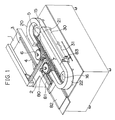
- Fig. 1 is a perspective view exemplarily showing a microwave heat sterilizer constructed according to this invention;
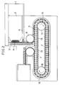
- Fig. 2 is a plan view showing the sterilizer of Fig. 1 with casings for preheating, hot air blasting and heat insulation having been removed;
- Fig. 3 is a plan view of a rail used in the sterilizer of Fig. 1;
- Fig. 4 is a sectional view taken along a line A-A in Fig. 3;
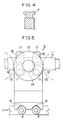
- Fig. 5 is a plan view showing a relationship between a
bucket 5 and an ampoule a; - Fig. 6 is a front view showing the bucket of Fig. 5 as holding the
rail 7 between; - Fig. 7 is a side view showing the bucket of Fig 5;
- Fig. 8 is a sectional view showing a relationship of the
bucket 5 with the casings for preheating, hot air blasting and heat insulation; - Fig. 9 is a sectional view of serially connected coaxial tube type microwave ovens;
- Fig. 10 is a front view showing, partially in a section, one of the coaxial tube type microwave ovens of Fig. 9;
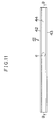
- Fig. 11 is a plan view showing a
rail 41 laid on the bottom of the coaxial tube type microwave oven; - Fig. 12 is a sectional view taken along a line B-B in Fig. 11;
- Fig. 13 is a sectional view showing an inlet side of the coaxial tube type microwave oven of Fig. 10 taken along a line C-C in Fig. 10;
- Fig. 14 is a sectional view showing an outlet side of the coaxial tube type microwave oven of Fig. 10 taken along a line D-D in Fig. 10;
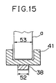
- Fig. 15 is a sectional view showing a relation between a width of an inner conductor provided in the coaxial tube type microwave oven and a diameter of the ampoule;
- Fig. 1 and Fig. 2 are perspective and plan views, respectively, of the sterilizer of the invention. Referring to these figures, a hopper 1 is equipped with a conveyor 3 used to supply ampoules a to a screw 2. A
mechanism 4 assures that the ampoules a can be reliably supplied even when they would not be properly engaged with the screw 2. Adjacent a forward end of the screw 2, there is provided astar wheel 6 serving to take the ampoules a out from the screw 2 and to supply them to abucket 5 of the sterilizer. - Within the sterilizer generally of an elliptical configuration, a correspondingly
elliptical rail 7 as shown by Fig. 3 is laid. Top of therail 7 has a cross-section laterally widened as seen in Fig. 4. - The
bucket 5 which is movable on therail 7 is of a configuration as shown by Fig. 5 through 7. More specifically, a forward end of abucket arm 8 is formed with a pair of recesses 9 adapted to hold the ampoules a and a base of saidarm 8 is provided on its underside with a pair ofmembers 10 each carrying a pair ofrollers 11 on its longitudinally opposite ends. Saidmembers 10 are pivotally supported onshafts 12, respectively, projecting downward from the underside of saidbucket arm 8. Therollers 11 are engaged with therail 7 from both sides so that thebucket arm 8 may smoothly move along therail 7. - The base of the
bucket arm 8 carries on its top adisc 13 is centrally provided with aprojection 14. - The
buckets 5 are mounted on therail 7 so as to be arranged in an elliptical array along therail 7 with saidrollers 11 being in engagement with therail 7 from both sides as shown by Fig. 7 and thediscs 13 of theadjacent buckets 5 being in contact with each other as shown by Fig. 2. Rotation ofsprockets buckets 5 of which thecentral projections 14 on thediscs 13 engaged withcircumferential grooves respective sprockets buckets 5 successively pass thesprockets discs 13 of therespective buckets 5 push one another and, consequently, all thebuckets 5 on therail 7 are moved clockwise along therail 7. - Referring to Fig. 1,
reference numerals - These casings have an inner construction common to them as shown by Fig. 8. The casing having a gate-shaped cross-section itself 23 is filled with a
heat insulator 24 between its outer wall 23o andinner wall 23i. Within the casing itself 23, there are provided a pair ofinfrared heaters opening 26 through which a stream of air heated by a heater (not shown) is blast into the casing. - In this embodiment, the
infrared heaters - A preheating temperature of these
infrared heaters - Referring to Fig. 8
reference numeral 27 designates an angle used to fasten the casing itself 23 onto a top surface of the sterilizer,reference numeral 28 designates a rail serving to support the ampoules a conveyed by thebuckets 5 from bottoms thereof andreference numeral 29 designates a guide used to protect the ampoules a against falling sideways. - Now referring to Fig. 1, the casing for hot air blasting 21 includes along its lower portion serially connected
microwave ovens - Figure 10 shows a co-axial tube type oven.
Reference numeral 32 designates an inlet side for the ampoules a into the oven andreference numeral 33 designates an outlet side for the ampoules a from the oven. The ampoules a conveyed by thebuckets 5 move in a direction as indicated by an arrow in Fig. 10 from right hand to left hand as viewed in Fig. 10. There are provided below themicrowave oven 30 and amicrowave oscillator 34 which is connected by awaveguide 36 to theoutlet side 33 of saidmicrowave oven 30 and amicrowave absorber 35 which is connected by awaveguide 37 to theinlet side 32 of themicrowave oven 30. Aninner conductor 38 is embedded in themicrowave oven 30 anddependant portions inner conductor 38 extending downward from longitudinally opposite ends thereof are received into thewaveguides microwave oscillator 34 is propagated by the inner conductor in a direction from theoutlet side 33 to theinlet side 32 of themicrowave oven 30. The direction in which the microwave is propagated is opposite to the direction in which the ampoules a are moved. - Fig. 13 and 14 are sectional views of the
microwave oven 30 as mentioned above, and it will be apparent that themicrowave oven 30 is formed in its top surface with aslot 54. With the bottoms being received into thisslot 54, the ampoules a are conveyed by thebuckets 5 within themicrowave oven 30 while they are irradiated with microwave. - There is laid a
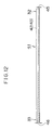
rail 41 above theinner conductor 38. As is best seen in Fig. 11 and 12, therail 41 has a U-shaped cross-section of which thelegs groove 44 therebetween so that the ampoules a may move with their bottom in contact with a floor of thegroove 44. The floor of thegroove 44 is relatively thin to theinlet side 32 as shown by athickness 45 and gradually thickened toward theoutlet side 33 of theoven 30 at a given ratio, as shown by athickness 46. While the instant embodiment employs therail 41 made of thermoplastic polymethylpentene (TPX; manufactured by Mitsui Petrochemical Industries, Ltd.),such rail 41 made of any other material such as Teflon which is heat resisting and microwave-unabsorbable may also be employed. - The
microwave oven 30 of coaxial tube type as has been described above presents a cross-sectional configuration as shown by Fig. 13 on its inlet side and a cross-sectional configuration as shown by Fig. 14 on its outlet side. As shown, theoven 30 has aheight 48 as measured from the oven's bottom 30′ to theinner conductor 38 on theinlet side 32 and this height is larger than acorresponding height 49 on theoutlet side 33 of theoven 30. As has previously been explained in reference with Fig. 12, therail 41 has thethickness 45 on theinlet side 32 less thanthickness 46 on theoutlet side 33 of theoven 30. In this manner, the slope of theinner conductor 38 and the thickness variation of therail 41 offset each other so that themicrowave oven 30 can provide auniform depth 50 over an extent spanning from theinlet side 32 to theoutlet side 33 of theoven 30 and thereby assure a horizontal surface along which the ampoules a move (see Fig. 9). - As best seen in Figs. 13 and 14, there is provided laterally of the slot 54 a
choke 51 serving to absorb the microwave which otherwise might escape upward along the ampoules a. In addition, theinner conductor 38 has awidth 52 smaller than adiameter 53 of each ampoule a so that the bottom of each ampoule a can be efficiently irradiated with the microwave. - Sterilization of the ampoules a is performed in the manner as has been described hereinabove and a subsequent handling is carried out using various means. Specifically, the sterilized ampoules a are successively taken by a
star wheel 80 out from therespective buckets 5 and these sterilized ampoules a are then delivered by saidstar wheel 80 to ascrew 81 which, in turn, feeds them onto adischarge tray 82.Reference numeral 83 designates an infrared radiation thermometer serving to take the temperature of the ampoules a having passed through themicrowave ovens - The sterilizer of the invention operates in a following manner:
- The ampoules a fed by the conveyor 3 into the hopper 1 are received in the helical groove of the screw 2 and carried to the
star wheel 6 which, in turn, delivers the ampoules a successively into the recesses 9 of therespective buckets 5. During such delivery, themechanism 4 assures that the ampoules a can be reliably delivered into the helical groove of the screw 2 even when they would not be properly engaged with the helical groove. - The ampoules a received by the
buckets 5 are moved clockwise as viewed in Fig. 2 as thesprockets casing 20 dedicated for this purpose. - Preheating of the ampoules a advantageously economizes a dose of microwave irradiation required in the
subsequent microwave ovens preheat casing 20 heats the ampoules a up to a given temperature, minimizing the unevenness of temperature. - The ampoules a thus preheated by the
casing 20 then pass through themicrowave ovens air blast casing 21 adapted to heat-sterilizing the upper portion of each ampoule a passing therethrough. - With the microwave oven of coaxial tube type, the dose of microwave irradiation for the ampoules a moving through the
slots 54 of therespective ovens oven inlet side 32 toward theoven outlet side 33 since the microwave is propagated by theinner conductor 38 from theoven outlet side 33 toward theoven inlet side 32. However, a degree of coupling between the medical fluid within each ampoule a and the microwave generally tends to decrease as the bottom of the ampoule a is spaced from theinner conductor 38. In this regard, the sterilizer of the invention is so constructed that theinner conductor 38 has theheight 48 on theoven inlet side 32 which is larger than theheight 49 on the oven outlet side 33 (as described in Fig. 9, Fig. 13 and Fig. 14) and thereby defines a slope and, consequently, the bottom of the ampoule a is more spaced from theinner conductor 38 on theoven outlet side 33 than on theoven inlet side 32. Within therespective microwave ovens oven outlet side 33 on which the dose of microwave irradiation is relatively high and said degree of coupling is relatively high on theoven inlet side 32 on which the dose of microwave irradiation is relatively low so that heating of the medical fluid within each ampoule a may be effected as gently as possible. - The
rail 41 has thethickness 45 on theoven inlet side 32 less than thethickness 46 on theoven outlet side 33 and thus are gradually thickened from theoven inlet side 32 toward theoven outlet side 33 at a given ratio as has previously been described in reference with Figs. 9 through 14. In this manner, the slope of theinner conductor 38 and the thickness variation of therail 41 offset each other so that themicrowave oven 30 can provide a uniform depth over an extent spanning between theoven inlet side 32 and theoven outlet side 33, assuring a horizontal surface along which the ampoules a are conveyed by thebuckets 5. - A pair of
microwave ovens respective microwave ovens - The temperature of the ampoules a having been sterilized by passage through the
microwave ovens air blast casing 21 is measured by theinfrared radiation thermometer 83. Thereafter, the ampoules a are carried by thebuckets 5 into thecasing 22 for heat insulation. - Upon completion of the sterilizing process, the ampoules a are taken by the
star wheel 80 out from thebuckets 5 and then conveyed by thescrew 81 onto thedischarge tray 82. - Through the specific embodiment shown adopts a pair of serially connected
microwave ovens
Claims (5)
- A sterilizer for sterilizing sealed containers (a) using microwave radiation, comprising a microwave oven (30, 31), in which the degree of coupling between the microwave radiation and the contents of the sealed containers (a) decreases from the inlet side (32) to the outlet side (33) of the microwave oven (30, 31), and the microwaves propogate from the outlet side (33) to the inlet side (32) of the microwave oven (30, 31), characterised in that the microwave oven (30, 31) is of the co-axial tube type, having an inner conductor (38) embedded in it, and in that the required degree of coupling is achieved by spacing the inner conductor (38) further from the base of the sealed containers (a) at the outlet end (33) than at the inlet end (32).
- A steriliser according to claim 1, having a plurality of serially connected co-axial tube type microwave ovens (30, 31), each having an embedded inner conductor (38), through which the sealed containers (a) are continuously moved.
- A sterilizer according to claim 1 or 2, in which the degree of coupling between the microwave radiation and the sealed containers (a) varies at a constant rate along the length of the, or each, microwave oven (30, 31).
- A sterilizer according to any one of the preceding claims, in which the, or each, microwave oven (30, 31) includes a U-shaped rail (41) which defines a groove (54) serving to hold the bottom of the sealed containers (a).
- A sterilizer according to claim 4, in which the U-shaped rail (41) overlies the inner conductor (38), and increases in thickness from the inlet side (32) to the outlet side (33) to reduce the coupling between the microwave radiation and the bottom of the sealed containers (a).
Applications Claiming Priority (4)
| Application Number | Priority Date | Filing Date | Title |
|---|---|---|---|
| JP24084/91 | 1991-01-24 | ||
| JP2408491 | 1991-01-24 | ||
| JP3352635A JPH05277166A (en) | 1991-01-24 | 1991-12-16 | Sterilizing device for hermetically sealed container utilizing microwave |
| JP352635/91 | 1991-12-16 |
Publications (2)
| Publication Number | Publication Date |
|---|---|
| EP0496633A1 EP0496633A1 (en) | 1992-07-29 |
| EP0496633B1 true EP0496633B1 (en) | 1995-10-04 |
Family
ID=26361572
Family Applications (1)
| Application Number | Title | Priority Date | Filing Date |
|---|---|---|---|
| EP92300610A Expired - Lifetime EP0496633B1 (en) | 1991-01-24 | 1992-01-24 | Microwave sterilizer for sealed containers |
Country Status (4)
| Country | Link |
|---|---|
| US (1) | US5279788A (en) |
| EP (1) | EP0496633B1 (en) |
| AT (1) | ATE128685T1 (en) |
| DE (1) | DE69205180T2 (en) |
Families Citing this family (9)
| Publication number | Priority date | Publication date | Assignee | Title |
|---|---|---|---|---|
| JPH0826226A (en) * | 1994-07-12 | 1996-01-30 | Eisai Co Ltd | Method and device for sterilization of hermetic container such as vial, etc. |
| US5839258A (en) * | 1995-11-28 | 1998-11-24 | Mitsubishi Chemical Corporation | Storing method for adsorbent particles |
| DE19622283A1 (en) * | 1996-05-23 | 1997-11-27 | Schering Ag | Process for the terminal sterilization of filled syringes |
| FR2884426B1 (en) * | 2005-04-19 | 2009-11-06 | Linac Technologies Sas Soc Par | INSTALLATION FOR THE STERILIZATION OF OBJECTS BY ELECTRON BOMBING. |
| US8375849B2 (en) | 2009-09-01 | 2013-02-19 | Manitowoc Foodservice Companies, Llc | Method and apparatus for an air inlet in a cooking device |
| US9120587B2 (en) * | 2010-09-10 | 2015-09-01 | Pepsico, Inc. | In-package non-ionizing electromagnetic radiation sterilization |
| TW201309352A (en) * | 2011-08-29 | 2013-03-01 | Golden Green Biotech Co Ltd | Sterilization method for liquid-prefilled ampoule |
| US9259273B2 (en) | 2012-10-16 | 2016-02-16 | Symmetry Medical Manufacturing, Inc. | Movable holder for medical instruments and associated methods |
| SE538635C2 (en) | 2014-09-15 | 2016-10-04 | Observe Medical Aps | Method for sterilizing a body fluid drainage system |
Family Cites Families (11)
| Publication number | Priority date | Publication date | Assignee | Title |
|---|---|---|---|---|
| US3555232A (en) * | 1968-10-21 | 1971-01-12 | Canadian Patents Dev | Waveguides |
| NL7008713A (en) * | 1969-06-16 | 1970-12-18 | ||
| FR2120402A5 (en) * | 1970-12-31 | 1972-08-18 | Soulier Joel | |
| FR2500707A1 (en) * | 1981-02-20 | 1982-08-27 | Electricite De France | Microwave material processor with detachable radiating elements - uses waveguide coupler with coaxial tappings along its length to permit fitting of different radiating elements |
| US4614514A (en) * | 1983-02-16 | 1986-09-30 | M/A Com, Inc. | Microwave sterilizer |
| US4599216A (en) * | 1983-11-21 | 1986-07-08 | Board Of Regents For The University Of Oklahoma | Apparatus for exposure to microwaves |
| SE451656B (en) * | 1986-02-11 | 1987-10-19 | Alfastar Ab | DEVICE FOR HEATING BY MICROVAGS ENERGY |
| US4822967A (en) * | 1987-03-10 | 1989-04-18 | Toppan Printing Co., Ltd. | Apparatus for sterilizing sealed food stuffs by microwave irradiation |
| JP2805009B2 (en) * | 1988-05-11 | 1998-09-30 | 株式会社日立製作所 | Plasma generator and plasma element analyzer |
| JP2721188B2 (en) * | 1988-07-29 | 1998-03-04 | エーザイ株式会社 | Method and apparatus for sterilizing ampules using microwaves |
| JP2928271B2 (en) * | 1989-06-09 | 1999-08-03 | エーザイ株式会社 | Sterilizer and sterilization method of sealed container using microwave |
-
1992
- 1992-01-22 US US07/824,003 patent/US5279788A/en not_active Expired - Fee Related
- 1992-01-24 AT AT92300610T patent/ATE128685T1/en active
- 1992-01-24 DE DE69205180T patent/DE69205180T2/en not_active Expired - Fee Related
- 1992-01-24 EP EP92300610A patent/EP0496633B1/en not_active Expired - Lifetime
Also Published As
| Publication number | Publication date |
|---|---|
| US5279788A (en) | 1994-01-18 |
| EP0496633A1 (en) | 1992-07-29 |
| ATE128685T1 (en) | 1995-10-15 |
| DE69205180D1 (en) | 1995-11-09 |
| DE69205180T2 (en) | 1996-04-04 |
Similar Documents
| Publication | Publication Date | Title |
|---|---|---|
| FI93081C (en) | Method and apparatus for sterilizing closed containers using microwaves | |
| US5279788A (en) | Sterilizer for sealed container utilizing microwave | |
| CN111418264B (en) | Heating system with enhanced temperature control | |
| KR0136107B1 (en) | Method and apparatus for microwave sterilization of ampules | |
| EP0282030B1 (en) | Microwave heating sterilizer | |
| KR950012436B1 (en) | Continuous Microwave Sterilizer for Food | |
| KR100198869B1 (en) | Microwave sterilizer for sealed containers | |
| JP2525405Y2 (en) | Container transport device in sterilizer | |
| JPH02307474A (en) | Heat sterilization of hermetically sealed packed product | |
| RU2036663C1 (en) | Method for sterilizing ampullated liquid injection preparations and apparatus for carrying out same | |
| JP2907446B2 (en) | Transport bucket in sterilization equipment for hermetically sealed containers using microwaves | |
| JPS6319185B2 (en) | ||
| JPH0636396B2 (en) | Microwave heating sterilizer | |
| JPH0466078A (en) | Sterilizing device | |
| JPH0761248B2 (en) | Microwave heating sterilization method | |
| JPH06343436A (en) | Method for thermal sterilizing treatment of food and its apparatus | |
| JPH0622537B2 (en) | Microwave heating sterilization method | |
| JP2798437B2 (en) | Microwave irradiation control method for sealed container | |
| JPS63133970A (en) | Nicrowave thermal sterilization | |
| JPH07205939A (en) | Method and device to sterilize sealed container by utilizing infrared ray heater | |
| JPH0651051B2 (en) | Far-infrared ray sterilization method and sterilization device for contents contained in package | |
| JPH01187074A (en) | Sterilization by microwave heating |
Legal Events
| Date | Code | Title | Description |
|---|---|---|---|
| PUAI | Public reference made under article 153(3) epc to a published international application that has entered the european phase |
Free format text: ORIGINAL CODE: 0009012 |
|
| AK | Designated contracting states |
Kind code of ref document: A1 Designated state(s): AT BE CH DE FR GB IT LI SE |
|
| 17P | Request for examination filed |
Effective date: 19920918 |
|
| 17Q | First examination report despatched |
Effective date: 19930816 |
|
| GRAA | (expected) grant |
Free format text: ORIGINAL CODE: 0009210 |
|
| AK | Designated contracting states |
Kind code of ref document: B1 Designated state(s): AT BE CH DE FR GB IT LI SE |
|
| REF | Corresponds to: |
Ref document number: 128685 Country of ref document: AT Date of ref document: 19951015 Kind code of ref document: T |
|
| REF | Corresponds to: |
Ref document number: 69205180 Country of ref document: DE Date of ref document: 19951109 |
|
| ITF | It: translation for a ep patent filed | ||
| ET | Fr: translation filed | ||
| PGFP | Annual fee paid to national office [announced via postgrant information from national office to epo] |
Ref country code: AT Payment date: 19960111 Year of fee payment: 5 |
|
| PGFP | Annual fee paid to national office [announced via postgrant information from national office to epo] |
Ref country code: SE Payment date: 19960119 Year of fee payment: 5 |
|
| PGFP | Annual fee paid to national office [announced via postgrant information from national office to epo] |
Ref country code: BE Payment date: 19960306 Year of fee payment: 5 |
|
| PLBE | No opposition filed within time limit |
Free format text: ORIGINAL CODE: 0009261 |
|
| 26N | No opposition filed | ||
| PG25 | Lapsed in a contracting state [announced via postgrant information from national office to epo] |
Ref country code: AT Effective date: 19970124 |
|
| PG25 | Lapsed in a contracting state [announced via postgrant information from national office to epo] |
Ref country code: SE Effective date: 19970125 |
|
| PG25 | Lapsed in a contracting state [announced via postgrant information from national office to epo] |
Ref country code: BE Effective date: 19970131 |
|
| BERE | Be: lapsed |
Owner name: MICRO DENSHI CO. LTD Effective date: 19970131 Owner name: EISAI CO. LTD Effective date: 19970131 |
|
| EUG | Se: european patent has lapsed |
Ref document number: 92300610.0 |
|
| PGFP | Annual fee paid to national office [announced via postgrant information from national office to epo] |
Ref country code: FR Payment date: 19980109 Year of fee payment: 7 |
|
| PGFP | Annual fee paid to national office [announced via postgrant information from national office to epo] |
Ref country code: GB Payment date: 19980115 Year of fee payment: 7 |
|
| PGFP | Annual fee paid to national office [announced via postgrant information from national office to epo] |
Ref country code: DE Payment date: 19980202 Year of fee payment: 7 |
|
| PGFP | Annual fee paid to national office [announced via postgrant information from national office to epo] |
Ref country code: CH Payment date: 19980205 Year of fee payment: 7 |
|
| PG25 | Lapsed in a contracting state [announced via postgrant information from national office to epo] |
Ref country code: GB Free format text: LAPSE BECAUSE OF NON-PAYMENT OF DUE FEES Effective date: 19990124 |
|
| PG25 | Lapsed in a contracting state [announced via postgrant information from national office to epo] |
Ref country code: LI Free format text: LAPSE BECAUSE OF NON-PAYMENT OF DUE FEES Effective date: 19990131 Ref country code: CH Free format text: LAPSE BECAUSE OF NON-PAYMENT OF DUE FEES Effective date: 19990131 |
|
| GBPC | Gb: european patent ceased through non-payment of renewal fee |
Effective date: 19990124 |
|
| REG | Reference to a national code |
Ref country code: CH Ref legal event code: PL |
|
| PG25 | Lapsed in a contracting state [announced via postgrant information from national office to epo] |
Ref country code: FR Free format text: LAPSE BECAUSE OF NON-PAYMENT OF DUE FEES Effective date: 19990930 |
|
| PG25 | Lapsed in a contracting state [announced via postgrant information from national office to epo] |
Ref country code: DE Free format text: LAPSE BECAUSE OF NON-PAYMENT OF DUE FEES Effective date: 19991103 |
|
| REG | Reference to a national code |
Ref country code: FR Ref legal event code: ST |
|
| PG25 | Lapsed in a contracting state [announced via postgrant information from national office to epo] |
Ref country code: IT Free format text: LAPSE BECAUSE OF NON-PAYMENT OF DUE FEES;WARNING: LAPSES OF ITALIAN PATENTS WITH EFFECTIVE DATE BEFORE 2007 MAY HAVE OCCURRED AT ANY TIME BEFORE 2007. THE CORRECT EFFECTIVE DATE MAY BE DIFFERENT FROM THE ONE RECORDED. Effective date: 20050124 |