EP0496435B1 - Sheet aligning apparatus - Google Patents
Sheet aligning apparatus Download PDFInfo
- Publication number
- EP0496435B1 EP0496435B1 EP92106436A EP92106436A EP0496435B1 EP 0496435 B1 EP0496435 B1 EP 0496435B1 EP 92106436 A EP92106436 A EP 92106436A EP 92106436 A EP92106436 A EP 92106436A EP 0496435 B1 EP0496435 B1 EP 0496435B1
- Authority
- EP
- European Patent Office
- Prior art keywords
- sheet
- sheets
- tray
- folding
- mode
- Prior art date
- Legal status (The legal status is an assumption and is not a legal conclusion. Google has not performed a legal analysis and makes no representation as to the accuracy of the status listed.)
- Expired - Lifetime
Links
- 238000007599 discharging Methods 0.000 claims description 17
- 230000004044 response Effects 0.000 claims description 6
- 239000000872 buffer Substances 0.000 description 8
- 238000001514 detection method Methods 0.000 description 8
- 238000010586 diagram Methods 0.000 description 7
- 230000007257 malfunction Effects 0.000 description 7
- 230000006870 function Effects 0.000 description 5
- 239000011521 glass Substances 0.000 description 5
- 230000015572 biosynthetic process Effects 0.000 description 4
- 230000000994 depressogenic effect Effects 0.000 description 4
- 230000009471 action Effects 0.000 description 3
- 230000000881 depressing effect Effects 0.000 description 3
- 238000004140 cleaning Methods 0.000 description 2
- 230000007246 mechanism Effects 0.000 description 2
- 206010047571 Visual impairment Diseases 0.000 description 1
- 230000000694 effects Effects 0.000 description 1
- 238000005286 illumination Methods 0.000 description 1
- 239000004973 liquid crystal related substance Substances 0.000 description 1
- 238000012986 modification Methods 0.000 description 1
- 230000004048 modification Effects 0.000 description 1
- 239000011347 resin Substances 0.000 description 1
- 229920005989 resin Polymers 0.000 description 1
Images


Classifications
-
- G—PHYSICS
- G03—PHOTOGRAPHY; CINEMATOGRAPHY; ANALOGOUS TECHNIQUES USING WAVES OTHER THAN OPTICAL WAVES; ELECTROGRAPHY; HOLOGRAPHY
- G03G—ELECTROGRAPHY; ELECTROPHOTOGRAPHY; MAGNETOGRAPHY
- G03G15/00—Apparatus for electrographic processes using a charge pattern
- G03G15/65—Apparatus which relate to the handling of copy material
- G03G15/6538—Devices for collating sheet copy material, e.g. sorters, control, copies in staples form
- G03G15/6541—Binding sets of sheets, e.g. by stapling, glueing
-
- B—PERFORMING OPERATIONS; TRANSPORTING
- B42—BOOKBINDING; ALBUMS; FILES; SPECIAL PRINTED MATTER
- B42C—BOOKBINDING
- B42C1/00—Collating or gathering sheets combined with processes for permanently attaching together sheets or signatures or for interposing inserts
- B42C1/12—Machines for both collating or gathering and permanently attaching together the sheets or signatures
-
- B—PERFORMING OPERATIONS; TRANSPORTING
- B65—CONVEYING; PACKING; STORING; HANDLING THIN OR FILAMENTARY MATERIAL
- B65H—HANDLING THIN OR FILAMENTARY MATERIAL, e.g. SHEETS, WEBS, CABLES
- B65H31/00—Pile receivers
- B65H31/04—Pile receivers with movable end support arranged to recede as pile accumulates
- B65H31/08—Pile receivers with movable end support arranged to recede as pile accumulates the articles being piled one above another
-
- B—PERFORMING OPERATIONS; TRANSPORTING
- B65—CONVEYING; PACKING; STORING; HANDLING THIN OR FILAMENTARY MATERIAL
- B65H—HANDLING THIN OR FILAMENTARY MATERIAL, e.g. SHEETS, WEBS, CABLES
- B65H31/00—Pile receivers
- B65H31/04—Pile receivers with movable end support arranged to recede as pile accumulates
- B65H31/12—Devices relieving the weight of the pile or permitting or effecting movement of the pile end support during piling
- B65H31/18—Positively-acting mechanical devices
-
- B—PERFORMING OPERATIONS; TRANSPORTING
- B65—CONVEYING; PACKING; STORING; HANDLING THIN OR FILAMENTARY MATERIAL
- B65H—HANDLING THIN OR FILAMENTARY MATERIAL, e.g. SHEETS, WEBS, CABLES
- B65H45/00—Folding thin material
- B65H45/12—Folding articles or webs with application of pressure to define or form crease lines
- B65H45/14—Buckling folders
- B65H45/142—Pocket-type folders
-
- G—PHYSICS
- G03—PHOTOGRAPHY; CINEMATOGRAPHY; ANALOGOUS TECHNIQUES USING WAVES OTHER THAN OPTICAL WAVES; ELECTROGRAPHY; HOLOGRAPHY
- G03G—ELECTROGRAPHY; ELECTROPHOTOGRAPHY; MAGNETOGRAPHY
- G03G15/00—Apparatus for electrographic processes using a charge pattern
- G03G15/65—Apparatus which relate to the handling of copy material
- G03G15/6582—Special processing for irreversibly adding or changing the sheet copy material characteristics or its appearance, e.g. stamping, annotation printing, punching
-
- B—PERFORMING OPERATIONS; TRANSPORTING
- B65—CONVEYING; PACKING; STORING; HANDLING THIN OR FILAMENTARY MATERIAL
- B65H—HANDLING THIN OR FILAMENTARY MATERIAL, e.g. SHEETS, WEBS, CABLES
- B65H2801/00—Application field
- B65H2801/24—Post -processing devices
- B65H2801/27—Devices located downstream of office-type machines
-
- G—PHYSICS
- G03—PHOTOGRAPHY; CINEMATOGRAPHY; ANALOGOUS TECHNIQUES USING WAVES OTHER THAN OPTICAL WAVES; ELECTROGRAPHY; HOLOGRAPHY
- G03G—ELECTROGRAPHY; ELECTROPHOTOGRAPHY; MAGNETOGRAPHY
- G03G2215/00—Apparatus for electrophotographic processes
- G03G2215/00362—Apparatus for electrophotographic processes relating to the copy medium handling
- G03G2215/00367—The feeding path segment where particular handling of the copy medium occurs, segments being adjacent and non-overlapping. Each segment is identified by the most downstream point in the segment, so that for instance the segment labelled "Fixing device" is referring to the path between the "Transfer device" and the "Fixing device"
- G03G2215/00417—Post-fixing device
- G03G2215/00421—Discharging tray, e.g. devices stabilising the quality of the copy medium, postfixing-treatment, inverting, sorting
-
- G—PHYSICS
- G03—PHOTOGRAPHY; CINEMATOGRAPHY; ANALOGOUS TECHNIQUES USING WAVES OTHER THAN OPTICAL WAVES; ELECTROGRAPHY; HOLOGRAPHY
- G03G—ELECTROGRAPHY; ELECTROPHOTOGRAPHY; MAGNETOGRAPHY
- G03G2215/00—Apparatus for electrophotographic processes
- G03G2215/00362—Apparatus for electrophotographic processes relating to the copy medium handling
- G03G2215/00367—The feeding path segment where particular handling of the copy medium occurs, segments being adjacent and non-overlapping. Each segment is identified by the most downstream point in the segment, so that for instance the segment labelled "Fixing device" is referring to the path between the "Transfer device" and the "Fixing device"
- G03G2215/00417—Post-fixing device
- G03G2215/00426—Post-treatment device adding qualities to the copy medium product
-
- G—PHYSICS
- G03—PHOTOGRAPHY; CINEMATOGRAPHY; ANALOGOUS TECHNIQUES USING WAVES OTHER THAN OPTICAL WAVES; ELECTROGRAPHY; HOLOGRAPHY
- G03G—ELECTROGRAPHY; ELECTROPHOTOGRAPHY; MAGNETOGRAPHY
- G03G2215/00—Apparatus for electrophotographic processes
- G03G2215/00362—Apparatus for electrophotographic processes relating to the copy medium handling
- G03G2215/00535—Stable handling of copy medium
- G03G2215/00556—Control of copy medium feeding
-
- G—PHYSICS
- G03—PHOTOGRAPHY; CINEMATOGRAPHY; ANALOGOUS TECHNIQUES USING WAVES OTHER THAN OPTICAL WAVES; ELECTROGRAPHY; HOLOGRAPHY
- G03G—ELECTROGRAPHY; ELECTROPHOTOGRAPHY; MAGNETOGRAPHY
- G03G2215/00—Apparatus for electrophotographic processes
- G03G2215/00362—Apparatus for electrophotographic processes relating to the copy medium handling
- G03G2215/00789—Adding properties or qualities to the copy medium
- G03G2215/00822—Binder, e.g. glueing device
- G03G2215/00827—Stapler
-
- G—PHYSICS
- G03—PHOTOGRAPHY; CINEMATOGRAPHY; ANALOGOUS TECHNIQUES USING WAVES OTHER THAN OPTICAL WAVES; ELECTROGRAPHY; HOLOGRAPHY
- G03G—ELECTROGRAPHY; ELECTROPHOTOGRAPHY; MAGNETOGRAPHY
- G03G2215/00—Apparatus for electrophotographic processes
- G03G2215/00362—Apparatus for electrophotographic processes relating to the copy medium handling
- G03G2215/00789—Adding properties or qualities to the copy medium
- G03G2215/00877—Folding device
-
- G—PHYSICS
- G03—PHOTOGRAPHY; CINEMATOGRAPHY; ANALOGOUS TECHNIQUES USING WAVES OTHER THAN OPTICAL WAVES; ELECTROGRAPHY; HOLOGRAPHY
- G03G—ELECTROGRAPHY; ELECTROPHOTOGRAPHY; MAGNETOGRAPHY
- G03G2215/00—Apparatus for electrophotographic processes
- G03G2215/00362—Apparatus for electrophotographic processes relating to the copy medium handling
- G03G2215/00919—Special copy medium handling apparatus
- G03G2215/00936—Bookbinding
Definitions
- the present invention relates to a sheet aligning apparatus useable with an image forming apparatus such as a copying machine, a printer and a laser beam printer, more particularly to a sheet aligning apparatus in connection with a sheet finisher for processing the sheets, after images are formed on the sheets by an image forming means of said image forming apparatus, by for example, stacking, aligning, sorting, stapling and/or folding the sheets.
- a sheet finisher comprising a stapler is known by which recording sheets discharged from an associated image forming apparatus are stacked and stapled.
- an image forming apparatus provided with an automatic original (document) feeder of circulation or recirculation type (RDF, RDH) which will hereinafter be called “RDF feeder” or an automatic document feeder of non-circulation type which will hereinafter be called “ADF feeder” are also known.
- RDF feeder automatic original (document) feeder of circulation or recirculation type
- ADF feeder automatic document feeder of non-circulation type
- the stapler is used with such an image forming apparatus, it is general that after one circulation of the originals are fed from the RDF feeder or the ADF feeder to an image reading station where the originals are read, the recording sheets (copy sheets, for example) on which images are formed from the one set of the originals are stapled by the stapler of the sheet finisher.
- the maximum number of sheets which the stapler can staple and therefore, an operator has to always care whether or not the number of originals set in the
- Japanese Laid-Open Patent Application No. 67105/1985 proposes that the sheets discharged from the image forming apparatus are counted using a sensor, and when the number becomes larger than the maximum staple number, the stapler does not operate, and instead, the image forming operation automatically stops after one set of originals is copied without continuing the further copying operation, irrespective of the number of copies preset to be taken.
- the unstapled copies are first to be taken out, in order to perform the second cycle.
- a sheet finisher provided with a sheet folding mechanism and a stacker is also conventional, which is connected with and used with an image forming apparatus to receive a sheet from the image forming apparatus and to fold the sheet as desired into a predetermined form, and discharge it to the stacker.
- the sheet folding mechanism is usually operated in association with a document feeder of the image forming apparatus, so that when a sheet folding mode is selected by a folding mode selector, the original is fed from the automatic document feeder to a predetermined position of the image forming apparatus.
- the sheet on which an image of the original is formed is discharged from the image forming apparatus and is introduced into a relatively long conveying passage of the sheet folding means.
- the sheet finisher of this type stacks the sheet on the stacker at a fixed receiving position irrespective of whether the sheets are folded or not folded.
- the recording sheets discharged from the image forming apparatus are of A3 size and A4 size in accordance with the sizes of the originals.
- both sheets are introduced into the folding passage, although the small size sheet (A4) is not to be folded.
- the folding passage is relatively long, with the result that the possibility of jam is higher and that wasteful electric power is consumed to unnecessarily operate various solenoids or other means for controlling the sheet transportation.
- the sheet receiving position of the stacker is fixed irrespective of whether the sheets are folded or not, a problem arises, that is, if a great number of z-folded sheets are stacked, the z-folded portions constitute a thicker stack, and the subsequent sheet can go into the folded part of the already stacked sheet. In the case of two-folded sheets are stacked, this does not occur, but because of the larger thickness of the folded portions, the subsequent sheets can abut the already stacked sheets to disturb the alignment of the sheets or become a cause of jam.
- some image forming apparatus is provided with a manual feeding means for allowing an operator to feed a copy sheet manually. This is provided in addition to determined size cassettes or a large capacity deck, to allow the operator to take copies in the size of post card or business card.
- the RDF feeder is usually not used, and instead, a book mode is selected wherein an original is placed on a platen glass by the operator.
- the image forming apparatus is provided with a means to discriminate the size of the sheet i.e. JP-OS 61-9668, as in the case of using the cassette or deck, it is possible to staple the copies.
- a means to discriminate the size of the sheet i.e. JP-OS 61-9668
- JP-OS 61-9668 a means to discriminate the size of the sheet
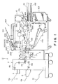
- Figure 1 is a sectional view of a sheet finisher connected to an image forming apparatus which is used therewith.
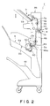
- Figure 2 is a sectional view of a sheet finisher containing a stapler and a stacker.
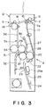
- Figure 3 is a sectional view of a sheet folder of a sheet finisher.
- Figures 4A and 4B are sectional views illustrating sheet folding actions in a two-folding mode, wherein Figure 4A shows the state wherein a loop is formed in the middle of the sheet, and Figure 4B shows the state wherein the sheet is two-folded at the center.
- Figures 5A - 5C illustrate various sheet folding modes, wherein Figure 5A shows a two-folding mode, Figure 5B shows a z-folding mode and Figure 5C shows a reversed z-folding mode.
- Figure 6 is a top plan view of the finisher apparatus and the folding apparatus.
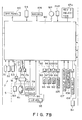
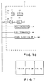
- Figure 7 is a block diagram illustrating a control of the sheet finisher.
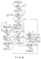
- Figure 8 is a flow chart illustrating the control operations.
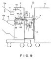
- Figures 9 and 10 are block diagrams for the control when the stapler is overcharged.
- Figure 11 is a flow chart illustrating the control system shown in Figures 9 and 10.
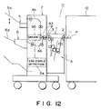
- Figure 12 is a block diagram illustrating a control when the stapler malfunctions.
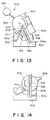
- Figures 13 and 14 illustrate a structure of a stapler.
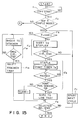
- Figure 15 is a flow chart illustrating operation when the stapler malfunctions.
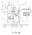
- Figure 16 is a block diagram for the control to prevent stapling of the same copies together.
- Figure 17 is a flow chart illustrating the control of Figure 16.
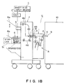
- Figure 18 is a block diagram for illustrating the control for a sheet aligning means i.e. sheet aligning apparatus.
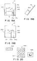
- FIGS 19A, 19B and 19C illustrate operation of the sheet aligning means.
- Figure 20 shows a part of operating portion of an image forming apparatus.
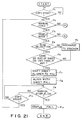
- Figure 21 illustrating a control of the sheet aligning means.
- Figure 22 is a block diagram for the control of the sheet folding means.
- Figure 23 is a flow chart illustrating the control of Figure 22.
- Figures 24A, 24B, 24C, 24D and 24E illustrate the operation of the stacker of a sheet finisher.
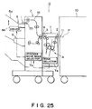
- Figure 25 is a block diagram for the control of the stacker.
- Figures 26 and 27 are flow chart for the control of the stacker.
- a sheet finisher U which is used with an image forming apparatus, more particularly, a copying machine.
- the sheet finisher U comprises a sheet folding device 1 and a finisher device 7, wherein they are joined so that the sheet discharge outlet 3 of the folding device 1 is in alignment with the sheet inlet 9 of the finisher device 7.
- the sheet finisher unit U is joined with copying apparatus (image forming apparatus) 10 equipped with an automatic original recirculation type document feeder (RDF) 200 in the manner that the sheet inlet 2 of the folding device 1 thereof is in alignment with a sheet discharge outlet 11 of the copying machine 10.
- RDF automatic original recirculation type document feeder
- the copy or recording sheet which will hereinafter be called “sheet” P discharged from the copying machine 10 can be folded by the folding device 1 into a predetermined shape, and is stacked on a stacker 5 of the finisher device 7 or on a stapler 6 to be stapled.
- the photosensitive drum 175 starts to rotate. Then, the drum 157 is subjected to a predetermined rotation control and a potential control. Then, an original placed on the platen glass is illuminated by an illumination lamp, and the light reflected by the original is directed by way of the scanning mirrors 152, 153, 154 and 155 and through the lens 156 onto a surface of the photosensitive drum 157 where an image is formed. Before the photosensitive drum 157 is exposed to the light image, it has been corona-charged with the aid of the high voltage unit 158. Thereafter, the photosensitive drum 157 is exposed to the light image, so that an electrostatic latent image is formed on the photosensitive drum 157.
- a sensor 305 is provided to detect completion of one cycle of the original circulation and produce a detection signal when the originals stacked on the stacking tray 201 are sequentially fed and all have been subjected to the image forming operation.
- the folding device 1 is provided with a couple of inlet rollers 13 in the sheet inlet 2 disposed at an upper position of the main body 12 of the sheet folding device 1. Downstream of the inlet roller couple 13 with respect to the movement direction of the sheet, there is an inlet deflector 15 disposed to selectively deflect the sheet in one direction or another, more particularly selectively to a through passage 16 or to a folding passage 17. At a downstream end of the through passage 16, there is a couple of discharging rollers 19, and downstream of the discharging roller couple 19, there is a sheet discharge outlet 3. The sheet discharge outlet 3 is disposed at substantially the same vertical level as that of the sheet inlet 2.
- folding means A Downstream of the sheet folding passage 17, there are various members constituting folding means A, which comprises a first folding roller 20, in the neighborhood of which a second folding roller 21 is disposed. Further, downstream of the first folding roller 20, there is disposed a first deflector 22 for selectively introducing the sheet P, conveyed from the folding passage 17, selectively to the first folding passage 23 or to a nip formed between the first folding roller 20 and the second folding roller 21. Downstream of the first folding passage 23, there are a first stopper 24 which is stationary and a movable stopper 25 which is actuatable by a solenoid 25a to project into the first folding passage 23.
- the operation panel 60a includes a mode selector switch of the finisher device 7, by which a stacking mode or stapling mode can be selected.
- the panel further includes displays 63 and 65 including a light emitting diode (LED) or lamp for displaying the mode selected by the switch 62.
- the display 65 displays a picture 66 representing the stacking mode.
- the display 63 indicates the stapling mode together with a picture 64 representing this mode.
- a mode selector switch 67 is provided in the operation panel 60b of the folding device 1, by which two-folding mode or z-folding mode can be selected.
- Displays 69 and 71 are effective to display the mode selected by the selector switch 67 by an LED or a lamp.
- the display 71 displays the two-folding mode together with picture 72 representing this mode.
- the display 69 displays the z-folding mode together with a picture display 70 illustrating this mode.
- Designated by a reference numeral 73 is a jam display for indicating occurrence of jam in the folding device 1 and the finisher device 7.
- the folding device 1 is operable selectively in one of five modes, in accordance with mode selection on the operation panel 60 and mode section between two-folding mode and z-folding mode and in accordance with detection signals from the original size detecting sensors 202 and 203 or a sheet size sensor 161a and 162a for detecting the sizes of the sides in the cassettes.
- the first mode is a through pass mode, which is executed when neither the two-folding mode or the z-folding mode is selected on the operation panel 60, and in this mode, the sheet is passed simply through the folding device 1. More particularly, the sheet P introduced from the sheet inlet 2 as shown in Figure 3, is directed to a through passage 16 by the inlet roller couple 13 and the inlet deflector 15, and then is discharged to the finisher device 7 through the sheet discharge outlet 3 by the discharging roller couple 19.
- the second mode is executed when either the two-folding mode or the z-folding mode is selected on the operation panel 60, and when half size sheets, i.e., A4 or B5 or smaller sheets are used.
- the sheet P introduced to the inlet deflector 15 by the inlet roller couple 13 is directed to the sheet folding passage 17, and is discharged through the sheet discharging outlet 3 by the discharging roller couple 19 after being passed between the first and second folding rollers 20 and 21, between the second and third folding rollers 21 and 29 and between the third and fourth folding rollers 29 and 33 and passing through the outlet passage 36, by the first, second and third deflectors 22, 26 and 31.
- Whether the sheet is of the half size or not is discriminated by signals from the sheet size sensor 161a, 162a for detecting the sizes of the sheet contained in the cassette 161 and 162.
- the third mode is a two-folding mode, which can be selected on the operation panel 60.
- A3, B4 or larger sheets are two-folded.
- the sheet P introduced from the inlet roller couple 13 to the sheet folding passage 17 by the inlet deflector 15 is directed to the first folding passage 23 by the operation of the first deflector 22.
- a loop X is formed in the middle of the sheet P.
- the loop X is expanded, as shown in Figure 4B, the loop is caught by the nip formed between the first folding roller 20 and the second folding roller 21, so that the sheet P is folded to form a crease P1 at the center of the sheet ( Figure 5A).
- the folded sheet P is introduced into between the second and third folding rollers 29 by the second deflector 26 and the third deflector 31. It is further conveyed between the third folding roller 29 and the fourth folding roller 33, and is discharged by the discharging roller couple 19 through the outlet passage 36.
- the fourth mode is a z-folding mode, wherein the sheet is first two-folded, and thereafter one side of the two-folded sheet is folded back.
- the sheet P introduced from the inlet roller couple 13 to the sheet folding passage 17 by the inlet deflector 15 is first introduced into the first folding passage 23 by the first deflector.
- a movable stopper 25 which has been projected thereinto by the solenoid 25a
- a loop is formed at a portion which is 1/4 away from the leading edge of the sheet P.
- the loop is gripped by the nip formed between the first and second folding rollers 20 and 21, so that a first crease or fold P2 is formed on the sheet P ( Figure 5B).
- the thus folded sheet P is introduced to the second passage 27 by the second deflector 26.
- a loop is similarly formed at a portion further about 1/4 away from the first crease P2 of the two-folded sheet P, and the loop is caught by the nip formed between the second and third folding rollers 21 and 29, so that a second fold or crease P3 is formed ( Figure 5B).
- the z-folded sheet which has been further folded to the front side is introduced into between the third and fourth roller couples 29 and 33 by the third deflector 31, and .uj0 is discharged to the finisher device 7 by the discharging roller 19 through the outlet passage 36.
- the folding device 1 there is a selection switch for making selection between a regular z-folding mode described above and a reversed z-folding mode ( Figure 7, 67a).
- the fifth mode is the reversed z-folding mode. This mode is executed when the z-folding mode is selected on the operation panel 60, and the reverse z-folding mode is selected by the selector switch 67a. In this mode, similarly to the above case, the sheet P introduced by the inlet roller couple 13 to the sheet folding passage 17 by the inlet deflector 15 is directed to between the first and second folding rollers 20 and 21 by the first deflector 22 and further to the second folding passage 27 by the second deflector.
- a sheet inlet 9 is disposed at front upper portion of the main body 39 of the finisher device, and is so disposed as to be at substantially the same level as the sheet discharging outlet 11 of the copying machine 10.
- an inlet roller couple 42 is disposed, and downstream of the inlet roller couple 42, an inlet deflector 43 actuatable by a solenoid 95 (driving means) to direct the sheet P from the sheet inlet 9 selectively to a passage 45 leading to the stacker station 5 or to a passage 46 leading to the stapler station 6. Downstream of the stacker passage 45, there is a discharging roller couple 47 to discharge the coming sheet P to the stacker 5a.
- Designated by the reference 60 is the operation panel described in conjunction with Figure 6.
- Designated by references S1, S2, S3 and S4 are the finisher inlet sensor, the stacker outlet sensor, intermediate tray outlet counter and the intermediate tray sheet detecting sensor, respectively.
- An up/down signal U/D and an ON/OFF signal are transmitted to a control circuit 77 through buffers 75 and 75 to control the upward and downward movements and on-off of the stacker station 5.
- a stacker motor M1 is controlled.
- the stacker station 5 is equipped with an upper limit sensor 79, a lower limit sensor 90 and a level detecting sensor S5. Those sensors are contributable to the control of the stacker motor M1.
- a motor M3 for shifting laterally the stacker station 5 is provided and is controlled by an SFT signal through a buffer 91.
- a signal 96 controls rotation of the stopper 40.
- the solenoid 99 is driven through a buffer 97, and the stapled sheets are allowed to fall onto the lower tray 41.
- a signal 110 is effective to drive the sheet conveying motor M1 through a buffer 111, and further, in accordance with a mode signal 112 representing the selected folding mode, associated plural deflectors and stoppers are properly actuated, and through a buffer 113, selected one of the five deflectors and stopper solenoid 115 are properly actuated.
- the control system includes an interruptor 116 for producing a pulse proportional to the rotational speed of the sheet conveying motor IM.
- step F1 When start of the copying operation of the copying machine 10 is detected at step F1, the folding device 1 and the finisher device 7 are instantaneously is placed in operative conditions. At step F2, an overflow bit which will hereinafter be called “OVF" is initialized to zero. At the next step, F3, the discrimination is made as to whether or not the mode is the RDF using and stapling mode. If not, the sequence goes to the flow A, which however is not directly related to a feature of this present embodiment, and therefore, the description of which is omitted. At the start of the copying operation, OVF is 0, and therefore, the sequence goes to step F5 from the step S4, so that a sheet P is discharged to the stapler station 6.
- OVF overflow bit which will hereinafter be called "OVF"
- the intermediate outlet counter S3 counts the discharged sheet P, and the discrimination is made as to whether or not the count reaches the maximum staplable number N (normally about 30). If not, the description is made as to whether or not one cycle of the original circulation is effected by the RDF feeder. If not, the above-described operations are repeated to the step F4.
- the sheets are stapled at step F7, and the stapled sheets P are allowed to fall onto the lower tray 41. Thereafter, at step F8 it is discriminated whether or not the preset number of copies are reproduced. If not, the next copying operation is prepared at step F9, and the sequence goes back to the step F4, and the operations are repeated until the preset number of copies are reproduced.
- step F10 the discrimination is made as to whether or not the one cycle of the circulation is completed by the RDF feeder. If the one cycle is completed just at the step F10, the sequence goes to step F7, and the subsequent operations are the same as described before.
- the copying machine 10 used with the sheet finishing unit U is provided with an automatic document feeder of an automatic recirculation type.
- the present invention is not limited to this, but is applicable to an automatic document feeder whereby the originals are automatically fed to a predetermined reading position of the copying machine 10.
- Figure 10 shows this embodiment, wherein when the stapling mode is selected, the originals stacked on the RDF feeder 200 are fed one by one from the RDF feeder 200 to the image leading station of the copying machine 10, and then they are returned to be stacked again on the RDF feeder 200.
- the number of originals is counted by an original counter S9.
- the counter S9 produces an output when the count is over the predetermined maximum staplable number by the stapling station.
- the sheet finisher unit U is provided with staple stopping means Y, which is responsive to the output signal of the original counter S9 to display, as desired, at the display 63 on the operation panel the exceeding of the number of originals on the RDF feeder 10' beyond the maximum staplable number, and/or prohibit copying operation of the copying machine 10, or to switch the conveyance of the sheet P to the stacker station 5.
- step F4 the number of originals on the RDF feeder 200 counted by the original counter S9, is below the maximum staplable number, the sequence goes to step F5, where the sheet P is discharged to the intermediate tray 6a of the stapling station 6, on which the bundle of sheets is stapled. Further, at step F6, the discrimination is made as to whether or not the preset number of copies have been reproduced. If not, the sequence goes back to step F5. The above described operations are repeated until the preset number of copies are taken. At step F4, if the count of the originals is larger than the stapling capability, the sequence goes to step F7, where the display to the effect is lit on.
- the finisher device 7 is provided with means S8 for detecting a malfunction of the stapler, particularly jam of the staple.
- the malfunction detecting means S8 detects the malfunction on the basis of the event that the driving source (generally a motor or plunger) for actuating the stapler does not operate at all or on the basis of the event that even if it is actuated, it does no return to its initial or home position within a predetermined period of time.
- the driving source generally a motor or plunger
- An example of the stapler malfunction detection is disclosed in Japanese Laid-Open Patent Application No. 64802/1985.
- a home position sensor 311 functions to detect whether or not the main assembly 304 is at the home position, that is, the stand-by position.
- the detecting arm 311a of the switch is engaged into a recess 312 of the cam 305 and produces a detection signal.
- step F1 the holding device 1 and the finisher device 7 are placed under the operative conditions, instantaneously.
- step F2 the description is made as to whether or not the mode is an RDF feeder using and stapling mode. If not, the sequence branches out to flow "A", which however is not directly connected with the present invention, and therefore the detailed explanation of which is omitted.
- step F3 the discrimination is made as to whether or not a stapler jam (SJAM) occurred in the past. If not, the inlet deflector 43 is switched by the solenoid 94 to discharge the sheet to the stapler station 6 at step F4.
- SJAM stapler jam
- step F6 the discrimination is performed as to whether or not the originals on the RDF feeder have circulated one cycle by the original cycle sensor 206. If not, the sequence goes back to step F3, and the operation is continued until one cycle is completed. If completed, the sequence goes to step F5, where the sheets are stapled, and a timer Ts is started. If the home position sensor 311 is not actuated after the timer period Ts elapses, that is, the stapler main assembly 304 is not restored to its home position, it is deemed that a stapler jam occurred and a jam flag SJAM is set to 1. At step F6, the description is made as to whether or not the preset number of copies has been taken or not. If no stapler jam is detected, the solenoid 99 is actuated to rotate the stepper 40, so that the stapled sheets are allowed to fall onto the bottom tray 41, and the sequence advances to step F6.
- step F6 If the preset number of copies are produced, the operation ends. If not, the next copying operation is prepared at step 7, and the sequence goes back to F3, and then, the above described operations are repeated until the preset number of copies are reproduced. Even if the occurrence of the stapler jam is detected, the operation ends if the preset number of copies are taken (step F6). However, even in this case, it is desirable that a clear warning is produced to the operator.
- step F9 the solenoid 95 is actuated to switch the inlet deflector 43, by which the subsequent set of sheets are discharged to the stacker station 5 which is capable of accommodating a larger number of sheets, until one cycle of the original circulation is completed.
- the stacker station 5 When the one cycle is completed, the stacker station 5 is horizontally shifted by actuating the motor M3 at step F10 so as to make easier the subsequent sorting operation of the sheets P. Then, at step F6 (through steps F7 and F3 if the preset number of copies are not taken), the subsequent sheets are all discharged to the stacker station 5 and are stacked thereon with lateral shifts for respective sets of copies.
- RDF recirculation type
- the present invention is not limited to this case, but is applicable to the copying machine provided with an automatic document feeder capable of automatically supplying the originals to a predetermined reading station of the copying machine.
- the finisher device 7 is provided with means Y2 for memorizing the number of image forming operations, which actuates the automatic document feeder, and it is effective to store the number of copies, the number of image forming operations, set in the copy number selector Y1 of the copying machine 10 when the stapling mode is selected.
- the finisher device 7 is further provided with means Y3 for prohibiting stapling operation, which is effective to prohibit the stapler from operating to staple plural copy sheets P from the same original image on the basis of the memory of the pluralism of the set number and to flicker a lamp 63 to provide an warning with the operator.
- step F1 the discrimination is made as to whether or not the mode is an ADF feeder using and stapling mode. If so, the discrimination is made, at step F2, as to whether or not the number of copies to be taken is plural, by the image formation number memorizing means Y2. If the result of the step F1 is negative, the sequential flow branches out to "A", which however is not directly concerned with the present invention, and therefore, detailed explanation of which is omitted for the sake of simplicity. If the number of copies set at step F2 is single, that is, 1, the sequence goes to step S3, where one copy is produced from one original, and the copy sheet P is discharged onto the intermediate tray 6a, and this is repeated. After completion of the sheet discharging for all the originals, the discharged copy sheets are stapled, and the operation ends (normal ADF operation).
- step F2 it is discriminated that the image formation number memorizing means Y2 stores a plural number of copies preset by the copy number selector Y1, some warning is produced to the operator at step F4. Simply, for example, the display lamp 63 representing the selection of stapling mode is flickered on the operation panel 60 of Figure 6. If the copying machine is provided with a liquid crystal display (LCD) by which a sentence can be displayed, "same copy sheets are to be stapled" or "check the preset number" may be displayed.
- LCD liquid crystal display
- step F6 if the operator desires the stapling mode copy despite the display, and depresses the copy start button, the sequence goes to step F6 from the step F5, and a preset number of copies is produced for each of the originals. After the preset number of copies are produced, the copy sheets are stapled, and the operations are repeated until the ADF feeder becomes empty.
- step F5 if it is prior to the start of copying operation, the sequence goes back to step F2, and the rechecking is effected as to whether it is the intentional preset number or not, and the above described control is continued. This is so done, in consideration of the possibility that the operator will reconsider whether to set the number to 1.
- the display 63 or the like when plural number of copies is memorized, the display 63 or the like is lit on to give an warning to the operator.
- the preset number is automatically reset to 1, and the copying operation is automatically performed, assuming automatically that the number is 1.
- the intermediate tray 6a is provided with a sheet aligning means including a reference or sheet abutting plate 401 and a sheet aligning plate 402.
- the sheet abutting plate 401 is fixed at one lateral end of the intermediate tray 6a.
- the sheet aligning plate 402 is laterally shiftable by a pulse motor in accordance with the sheet size signal from the sheet size sensor 161a and 162a of the cassette or under the control of control means C' when the copy sheet is fed manually which will be described.
- the distance l 1 between the sheet P and the sheet abutting plate 401 shown in Figure 19A and a distance l 2 between the sheet aligning plate 402 shifted to the predetermined position PO2 and the sheet P is approximately 5 mm, respectively.
- the sheet aligning plate 402 moves from the predetermined position PO2 to a sheet urging position PO3 prior to the sheet becoming still. And then, the sheet aligning plate 402 is returned to the predetermined position PO2.
- the sheet aligning plate 402 moves and returns, so that the sheets P are aligned at their lateral edges.
- the stapling means i.e., the stapler 52 is disposed above the lower end of the intermediate tray 6a, and the sheets P on the intermediate tray 6a are stapled at a position ST adjacent to the sheet abutting plate 401 shown in Figure 19C.
- the operation panel 175 is provided with a copy number display 403, ten keys 405, copy start button 406 and others.
- the copy number is inputted by the ten keys 405, the number is displayed on the copy number display 403.
- the copy button 406 is depressed, the copy operation starts.
- the sheet is to be stapled, the stapling mode is selected.
- the size of the sheet or sheets manually supplied is inputted by a sheet size inputting means C.
- the inputting means is provided in the copying machine or in the sheet finisher unit and is constituted by ten keys or dial. It is possible that the ten keys 405 are commonly used.
- the width of the sheet to be manually fed is inputted by first depressing an asterisk key 407 of the ten keys 405, then inputting the width by the ten keys 405 and finally depressing the asterisk key 407 again.
- the size of the sheet is 297 mm, "* 207 *" is inputted.
- the sheet P When the sheet P is supplied from the sheet supplying station of the copying machine 10, more particularly, from the sheet cassette 161 or 162 or from the deck 163, and when the stapling mode is selected, the sheet P introduced through a predetermined passage from the sheet inlet 9 by the conveying roller couple 42 is introduced to a stapler conveying passage 46 by the inlet deflector 43, and is once discharged onto the intermediate tray 6a by the stapler discharging roller couple 49. The sheet P is then aligned in the longitudinal and lateral directions and placed on the intermediate tray 6a.
- the sheets P thus placed in order on the intermediate tray 6a are stapled by the stapler 51. Subsequently, the sheets stapled by rotation of the stopper 40 are allowed to fall on the lower tray 41 and are accommodated there.
- the sheet P introduced to the finisher device 7 through a predetermined passage is discharged onto the stacker station 5 at step F5. At this time, it is possible that the copying operation of the copying machine 10 is prohibited.
- the case of the sheet size inputted will be described.
- the discrimination is made as to whether or not the size of the sheet on the intermediate tray 6a is the same as the inputted sheet size at step F6. If not, the sheet introduced into the finisher device 7 is discharged to the stacker station 5 (F5). If the sizes are the same, the sheet aligning plate 72 of the intermediate tray 6a is shifted to a position PO2 corresponding to the sheet size inputted, at step F7.
- the sheet P is guided by the inlet deflector 43 switched to the stapler passage 46 side, and is aligned on the intermediate tray 6a at step F8.
- a manual stapling button is depressed at step F9, the sheets are stapled by the stapler 51, and then are allowed to fall onto the lower tray 41 where they are accommodated there at step F10. If the copying operation is started (F1) with the manual stapling button not depressed, after the sheet is aligned on the intermediate tray 6a, the above described operations are repeated.
- the sheet finisher unit is provided with means Y4 for discriminating necessity and unnecessity of sheet folding.
- the function of the discriminating means Y4 is performed by the microcomputer MC of Figure 7.
- the microcomputer MC0 is responsive to the detection signal thereof or to a copy magnification inputted on the operation panel 175 and the detection signal thereof, and to select that one of cassettes 161, 162 and deck 163 which accommodates a corresponding size of sheets.
- the feeding means is controlled so as to feed out the sheet from the selected cassette or deck.
- the discriminating means Y4 discriminates in accordance with the sheet size signal from the main body of the image forming apparatus whether or not the folding is needed.
- the sheet size is detected using the original size detecting sensors 202 and 203 of the RDF feeder or using the sheet size sensors 161a and 162a of the selected cassette.
- the operation of the stacker 5 will be described in conjunction with the flow chart of this Figure.
- the copy start button is depressed on the operation panel 175 ( Figure 7) at step F1
- a stacker mode is selected on the operation panel 60 ( Figure 7) or is selected for the finisher device 7 at step F2
- the stacker 5a is lifted to the topmost position (the solid line lever l position) detectable by the level detecting sensor S5 under the control of the stacker movement mode setting means Y5.
Landscapes
- Engineering & Computer Science (AREA)
- Mechanical Engineering (AREA)
- Physics & Mathematics (AREA)
- General Physics & Mathematics (AREA)
- Folding Of Thin Sheet-Like Materials, Special Discharging Devices, And Others (AREA)
Description
- The present invention relates to a sheet aligning apparatus useable with an image forming apparatus such as a copying machine, a printer and a laser beam printer, more particularly to a sheet aligning apparatus in connection with a sheet finisher for processing the sheets, after images are formed on the sheets by an image forming means of said image forming apparatus, by for example, stacking, aligning, sorting, stapling and/or folding the sheets.
- A sheet finisher comprising a stapler is known by which recording sheets discharged from an associated image forming apparatus are stacked and stapled. On the other hand, an image forming apparatus provided with an automatic original (document) feeder of circulation or recirculation type (RDF, RDH) which will hereinafter be called "RDF feeder" or an automatic document feeder of non-circulation type which will hereinafter be called "ADF feeder", are also known. When the stapler is used with such an image forming apparatus, it is general that after one circulation of the originals are fed from the RDF feeder or the ADF feeder to an image reading station where the originals are read, the recording sheets (copy sheets, for example) on which images are formed from the one set of the originals are stapled by the stapler of the sheet finisher. Naturally, however, there is a limitation that the maximum number of sheets which the stapler can staple, and therefore, an operator has to always care whether or not the number of originals set in the ADF or RDF feeder is less than the maximum number.
- If the operator does not care the number of originals, the staple can be jammed due to the over charge. In order to prevent this, Japanese Laid-Open Patent Application No. 67105/1985 proposes that the sheets discharged from the image forming apparatus are counted using a sensor, and when the number becomes larger than the maximum staple number, the stapler does not operate, and instead, the image forming operation automatically stops after one set of originals is copied without continuing the further copying operation, irrespective of the number of copies preset to be taken. In this system, the unstapled copies are first to be taken out, in order to perform the second cycle. However, for the very reason that the image forming apparatus is equipped with the RDF feeder, the operator usually leaves away from the image forming apparatus after setting the originals and depressing the copy button. Therefore, with the above proposal, much time is lossed by the discontinuance if a number of copies were to be copied.
- A sheet finisher provided with a sheet folding mechanism and a stacker is also conventional, which is connected with and used with an image forming apparatus to receive a sheet from the image forming apparatus and to fold the sheet as desired into a predetermined form, and discharge it to the stacker. The sheet folding mechanism is usually operated in association with a document feeder of the image forming apparatus, so that when a sheet folding mode is selected by a folding mode selector, the original is fed from the automatic document feeder to a predetermined position of the image forming apparatus. The sheet on which an image of the original is formed is discharged from the image forming apparatus and is introduced into a relatively long conveying passage of the sheet folding means. The sheet finisher of this type stacks the sheet on the stacker at a fixed receiving position irrespective of whether the sheets are folded or not folded.
- When the set of originals placed on the automatic document feeder contains mingled A3 size sheets and A4 size sheets, the recording sheets discharged from the image forming apparatus are of A3 size and A4 size in accordance with the sizes of the originals. However, both sheets are introduced into the folding passage, although the small size sheet (A4) is not to be folded. The folding passage is relatively long, with the result that the possibility of jam is higher and that wasteful electric power is consumed to unnecessarily operate various solenoids or other means for controlling the sheet transportation.
- Also, if the sheet receiving position of the stacker is fixed irrespective of whether the sheets are folded or not, a problem arises, that is, if a great number of z-folded sheets are stacked, the z-folded portions constitute a thicker stack, and the subsequent sheet can go into the folded part of the already stacked sheet. In the case of two-folded sheets are stacked, this does not occur, but because of the larger thickness of the folded portions, the subsequent sheets can abut the already stacked sheets to disturb the alignment of the sheets or become a cause of jam.
- Recently, some image forming apparatus is provided with a manual feeding means for allowing an operator to feed a copy sheet manually. This is provided in addition to determined size cassettes or a large capacity deck, to allow the operator to take copies in the size of post card or business card. When the apparatus is operated in the manual feed mode, the RDF feeder is usually not used, and instead, a book mode is selected wherein an original is placed on a platen glass by the operator.
- If the image forming apparatus is provided with a means to discriminate the size of the sheet i.e. JP-OS 61-9668, as in the case of using the cassette or deck, it is possible to staple the copies. However, usually, when the sheet is supplied manually, arbitrary sizes of sheets are supplied, it is difficult to discriminate the sizes of the sheets, and therefore, it is practically not possible to staple them. This is because when the sheets are to be stapled, it is required that the sheets are aligned in order, were which would not be possible if the sizes of the sheets were not known.
-
- It is an object of the present invention to provide a sheet aligning apparatus wherein the sheets or the bundles of sheets to be stapled are aligned with high precision.
- It is a further object of the present invention to provide a sheet aligning apparatus wherein various sizes of copy sheets are aligned with high precision to allow them to be stapled in good order.
- It is a further object of the present invention to provide a sheet aligning apparatus wherein a great number of folded sheets can be stacked just as the unfolded sheets.
- These and other objects, features and advantages of the present invention will become more apparent upon a consideration of the following description of the preferred embodiments of the present invention taken in conjunction with the accompanying drawings.
- Figure 1 is a sectional view of a sheet finisher connected to an image forming apparatus which is used therewith.
- Figure 2 is a sectional view of a sheet finisher containing a stapler and a stacker.
- Figure 3 is a sectional view of a sheet folder of a sheet finisher.
- Figures 4A and 4B are sectional views illustrating sheet folding actions in a two-folding mode, wherein Figure 4A shows the state wherein a loop is formed in the middle of the sheet, and Figure 4B shows the state wherein the sheet is two-folded at the center.
- Figures 5A - 5C illustrate various sheet folding modes, wherein Figure 5A shows a two-folding mode, Figure 5B shows a z-folding mode and Figure 5C shows a reversed z-folding mode.
- Figure 6 is a top plan view of the finisher apparatus and the folding apparatus.
- Figure 7 is a block diagram illustrating a control of the sheet finisher.
- Figure 8 is a flow chart illustrating the control operations.
- Figures 9 and 10 are block diagrams for the control when the stapler is overcharged.
- Figure 11 is a flow chart illustrating the control system shown in Figures 9 and 10.
- Figure 12 is a block diagram illustrating a control when the stapler malfunctions.
- Figures 13 and 14 illustrate a structure of a stapler.
- Figure 15 is a flow chart illustrating operation when the stapler malfunctions.
- Figure 16 is a block diagram for the control to prevent stapling of the same copies together.
- Figure 17 is a flow chart illustrating the control of Figure 16.
- Figure 18 is a block diagram for illustrating the control for a sheet aligning means i.e. sheet aligning apparatus.
- Figures 19A, 19B and 19C illustrate operation of the sheet aligning means.
- Figure 20 shows a part of operating portion of an image forming apparatus.
- Figure 21 illustrating a control of the sheet aligning means.
- Figure 22 is a block diagram for the control of the sheet folding means.
- Figure 23 is a flow chart illustrating the control of Figure 22.
- Figures 24A, 24B, 24C, 24D and 24E illustrate the operation of the stacker of a sheet finisher.
- Figure 25 is a block diagram for the control of the stacker.
- Figures 26 and 27 are flow chart for the control of the stacker.
- Referring to Figure 1, there is shown a sheet finisher U which is used with an image forming apparatus, more particularly, a copying machine. The sheet finisher U comprises a
sheet folding device 1 and afinisher device 7, wherein they are joined so that thesheet discharge outlet 3 of thefolding device 1 is in alignment with thesheet inlet 9 of thefinisher device 7. The sheet finisher unit U is joined with copying apparatus (image forming apparatus) 10 equipped with an automatic original recirculation type document feeder (RDF) 200 in the manner that the sheet inlet 2 of thefolding device 1 thereof is in alignment with asheet discharge outlet 11 of thecopying machine 10. By those apparatuses combined in this manner, the copy or recording sheet which will hereinafter be called "sheet" P discharged from thecopying machine 10 can be folded by thefolding device 1 into a predetermined shape, and is stacked on astacker 5 of thefinisher device 7 or on astapler 6 to be stapled. - The
copying machine 10 includes aplaten glass 151 for supporting an original to be copied, scanningmirrors lens 156 having a focusing and magnification changing functions. Thecopying machine 10 further comprises a photosensitive drum 57, ahigh voltage unit 158, a developingdevice 159, atransfer charger 159 and acleaning device 160. - For the sheet handling, the
copying machine 10 further comprises alower cassette 162, asheet feeding deck 163,pickup rollers registration roller 167. It further comprises animage fixing device 169, aconveyor belt 168 for conveying a sheet having an image to thefixing device 169, a conveyingroller 171 and asheet sensor 171a. - It includes a
deflector 172 for selectively introducing a sheet to adischarge roller 11 or to a reversingtray unit 173. A manualsheet feeding tray 175 is provided to allow an operator to feed manually a recording sheet. - In response to actuation of a copy start key which will be described, the
photosensitive drum 175 starts to rotate. Then, thedrum 157 is subjected to a predetermined rotation control and a potential control. Then, an original placed on the platen glass is illuminated by an illumination lamp, and the light reflected by the original is directed by way of the scanning mirrors 152, 153, 154 and 155 and through thelens 156 onto a surface of thephotosensitive drum 157 where an image is formed. Before thephotosensitive drum 157 is exposed to the light image, it has been corona-charged with the aid of thehigh voltage unit 158. Thereafter, thephotosensitive drum 157 is exposed to the light image, so that an electrostatic latent image is formed on thephotosensitive drum 157. - The electrostatic latent image thus formed on the
photosensitive drum 157 is developed by a developingroller 159a of the developingdevice 159 so that a visualized image is formed with toner, and the toner image is transferred onto a transfer sheet by thetransfer charger 159. - On the other hand, the transfer sheet is discharged from the
upper cassette 161, thelower cassette 162 or thedeck 163 by thepickup roller registration roller 167 so that a loop of the sheet is formed. Theregistration roller 167 refeeds the once stopped sheet in such a timed relation that the leading edge of the sheet is brought into alignment with the leading edge of the image formed on thephotosensitive drum 157 which is rotating. When the sheet passes through between thephotosensitive drum 157 and thetransfer charger 159, the toner image on thephotosensitive drum 157 is transferred onto the sheet. After the image transfer, the sheet is separated from thephotosensitive drum 157 and is directed by the conveyingbelt 168 to theimage fixing device 169 where the image is fixed by pressure and heat thereon. Then, the sheet is discharged by the conveyingroller 171 and thedischarge roller 11. If the sheet is not detected by thesheet sensor 171a at the predetermined timing, it is deemed that jam has occurred to require the operator to clear the jam. - When plural image forming operations are to be effected on the same sheet, a duplex mode or superimposing mode is inputted in the
operation panel 175 of the copying machine. Then, the sheet is introduced by thedeflector 172 to the reversingtray unit 173 and is fed to thephotosensitive drum 157 again through the conveyingpassage 174. - The
photosensitive drum 157 surface, after the image has been transferred, is brought to thecleaning device 160 where the surface of thephotosensitive drum 157 is cleaned to be prepared for the next image forming operation. - The
RDF feeder 200 includes a stackingtray 201 for stacking originals to be copied andsensors sensors sensor - The original fed to the
platen glass 151 through thesheet passage 204 from the stackingtray 201 is returned through thesheet passage 205 to the stackingtray 201 where it is stacked again. - Where both sides of the original are to be copied, the original is once conveyed to the original supporting
platen 105, and is then conveyed to thesheet passage 205 without being subjected to the image forming operation on theplaten 105, and is stopped halfway in thesheet passage 205, and then is reversely transported. Thereafter, it is transported to thesheet passages sheet passage 208 and is reversely conveyed (switch-back), and the second side of the original is first subjected to the image formation on the original supportingplaten 151. Then, it is fed to thesheet passage 205 again, and is reversed halfway of thesheet passage 205, then is transported to thesheet passages platen 151. Now, the first side of the original is subjected to the image forming operation, and thereafter, it is conveyed through thesheet passage 205 and is discharged onto the stackingtray 201, where it is stacked. In this embodiment, when both sides are to be copied, a duplex mode is selected in anoperation panel 175 of theapparatus 10. - A
sensor 305 is provided to detect completion of one cycle of the original circulation and produce a detection signal when the originals stacked on the stackingtray 201 are sequentially fed and all have been subjected to the image forming operation. - As shown in Figure 3, the
folding device 1 is provided with a couple ofinlet rollers 13 in thesheet inlet 2 disposed at an upper position of themain body 12 of thesheet folding device 1. Downstream of theinlet roller couple 13 with respect to the movement direction of the sheet, there is aninlet deflector 15 disposed to selectively deflect the sheet in one direction or another, more particularly selectively to a throughpassage 16 or to afolding passage 17. At a downstream end of the throughpassage 16, there is a couple of dischargingrollers 19, and downstream of the dischargingroller couple 19, there is asheet discharge outlet 3. Thesheet discharge outlet 3 is disposed at substantially the same vertical level as that of thesheet inlet 2. Downstream of thesheet folding passage 17, there are various members constituting folding means A, which comprises afirst folding roller 20, in the neighborhood of which asecond folding roller 21 is disposed. Further, downstream of thefirst folding roller 20, there is disposed afirst deflector 22 for selectively introducing the sheet P, conveyed from thefolding passage 17, selectively to thefirst folding passage 23 or to a nip formed between thefirst folding roller 20 and thesecond folding roller 21. Downstream of thefirst folding passage 23, there are afirst stopper 24 which is stationary and amovable stopper 25 which is actuatable by asolenoid 25a to project into thefirst folding passage 23. Downstream of thefirst folding roller 20 and thesecond folding roller 21, asecond deflector 26 is disposed to introduce the sheet selectively to thesecond folding passage 27 or to a nip formed between thesecond folding roller 21 and athird folding roller 29 adjacent to thesecond folding roller 21. Downstream of thesecond folding passage 27, there is a secondstationary stopper 30. Downstream of the second andthird folding rollers third deflector 31 to introduce the sheet P selectively to athird folding passage 32 or to a nip formed between thethird folding roller 29 and afourth folding roller 33 adjacent to thethird folding roller 29. Downstream of thethird folding passage 32, there is a thirdstationary stopper 35. Downstream of the third andfourth folding rollers passage 36 is merged with the conveyingpassage 16, and then communicates with thesheet discharge outlet 3. - Referring to Figure 6, there is shown an
operating panel 60 of thefinisher device 7 and thefolding device 1, whereinreference 60a designates an operation panel of thefinisher device 7, andreference 60b that of thefolding device 1. Theoperation panel 60a includes a mode selector switch of thefinisher device 7, by which a stacking mode or stapling mode can be selected. The panel further includesdisplays switch 62. Thedisplay 65 displays apicture 66 representing the stacking mode. Thedisplay 63 indicates the stapling mode together with apicture 64 representing this mode. - A
mode selector switch 67 is provided in theoperation panel 60b of thefolding device 1, by which two-folding mode or z-folding mode can be selected.Displays selector switch 67 by an LED or a lamp. Thedisplay 71 displays the two-folding mode together withpicture 72 representing this mode. Thedisplay 69 displays the z-folding mode together with apicture display 70 illustrating this mode. Designated by areference numeral 73 is a jam display for indicating occurrence of jam in thefolding device 1 and thefinisher device 7. - The
folding device 1 is operable selectively in one of five modes, in accordance with mode selection on theoperation panel 60 and mode section between two-folding mode and z-folding mode and in accordance with detection signals from the originalsize detecting sensors sheet size sensor - The first mode is a through pass mode, which is executed when neither the two-folding mode or the z-folding mode is selected on the
operation panel 60, and in this mode, the sheet is passed simply through thefolding device 1. More particularly, the sheet P introduced from thesheet inlet 2 as shown in Figure 3, is directed to a throughpassage 16 by theinlet roller couple 13 and theinlet deflector 15, and then is discharged to thefinisher device 7 through thesheet discharge outlet 3 by the dischargingroller couple 19. - The second mode is executed when either the two-folding mode or the z-folding mode is selected on the
operation panel 60, and when half size sheets, i.e., A4 or B5 or smaller sheets are used. In this mode, the sheet P introduced to theinlet deflector 15 by theinlet roller couple 13 is directed to thesheet folding passage 17, and is discharged through thesheet discharging outlet 3 by the dischargingroller couple 19 after being passed between the first andsecond folding rollers third folding rollers fourth folding rollers outlet passage 36, by the first, second andthird deflectors - Whether the sheet is of the half size or not is discriminated by signals from the
sheet size sensor cassette - The third mode is a two-folding mode, which can be selected on the
operation panel 60. In this mode, A3, B4 or larger sheets are two-folded. The sheet P introduced from theinlet roller couple 13 to thesheet folding passage 17 by theinlet deflector 15 is directed to thefirst folding passage 23 by the operation of thefirst deflector 22. As shown in Figure 4A, when the leading edge of the sheet P is abutted to the firststationary stopper 24, a loop X is formed in the middle of the sheet P. When the loop X is expanded, as shown in Figure 4B, the loop is caught by the nip formed between thefirst folding roller 20 and thesecond folding roller 21, so that the sheet P is folded to form a crease P1 at the center of the sheet (Figure 5A). The folded sheet P is introduced into between the second andthird folding rollers 29 by thesecond deflector 26 and thethird deflector 31. It is further conveyed between thethird folding roller 29 and thefourth folding roller 33, and is discharged by the dischargingroller couple 19 through theoutlet passage 36. - The fourth mode is a z-folding mode, wherein the sheet is first two-folded, and thereafter one side of the two-folded sheet is folded back. In this mode, the sheet P introduced from the
inlet roller couple 13 to thesheet folding passage 17 by theinlet deflector 15 is first introduced into thefirst folding passage 23 by the first deflector. When the leading edge of the sheet P is abutted to amovable stopper 25 which has been projected thereinto by thesolenoid 25a, a loop is formed at a portion which is 1/4 away from the leading edge of the sheet P. The loop is gripped by the nip formed between the first andsecond folding rollers second passage 27 by thesecond deflector 26. When the first crease P2 thereof abuts the secondstationary stopper 30, a loop is similarly formed at a portion further about 1/4 away from the first crease P2 of the two-folded sheet P, and the loop is caught by the nip formed between the second andthird folding rollers third deflector 31, and .uj0 is discharged to thefinisher device 7 by the dischargingroller 19 through theoutlet passage 36. - In the
folding device 1, there is a selection switch for making selection between a regular z-folding mode described above and a reversed z-folding mode (Figure 7, 67a). - The fifth mode is the reversed z-folding mode. This mode is executed when the z-folding mode is selected on the
operation panel 60, and the reverse z-folding mode is selected by theselector switch 67a. In this mode, similarly to the above case, the sheet P introduced by theinlet roller couple 13 to thesheet folding passage 17 by theinlet deflector 15 is directed to between the first andsecond folding rollers first deflector 22 and further to thesecond folding passage 27 by the second deflector. However, when the leading edge of the sheet P is abutted to the secondstationary stopper 30, a loop is formed at a portion about 1/4 away from the leading edge of the sheet P and is caught by the nip formed between the second andthird folding rollers - Thereafter, the sheet P is introduced into the
third folding passage 32 by the third deflector, when the crease P4 of the sheet P is abutted to the thirdstationary stopper 35, by which a loop is formed at a portion further about 1/4 away from the crease P4 of the sheet P, and the loop is gripped by the nip formed between the third andfourth folding rollers - The reverse z-folded sheet P which has been folded reversely is discharged by the discharging
roller couple 19 through theoutlet passage 36. - Referring back to Figure 3, there are provided an inlet sensor S6, a folded sheet detecting sensor S7 for measuring the length of the folded sheet P.
- Further referring back to Figure 2, the
finisher device 7 is provided at a rear upper position of the main body of thefinisher device 7 with astacker station 5 including astacker 5a, thestacker station 5 being vertically and horizontally reciprocable by driving means such as motor or the like. Thestacker station 5 is further provided at a lower position with anintermediate tray 6a for astapler 6. To the bottom end of theintermediate tray 6a, astopper 40 is rotatably mounted and is effective to stop an end of the sheet P on thetray 6a. Below thestapler station 6, there is alower tray 41, on which the sheets P on theintermediate tray 6a is fallen by the rotation of thestopper 40, and the fallen sheets are accommodated on thelower tray 41. Asheet inlet 9 is disposed at front upper portion of themain body 39 of the finisher device, and is so disposed as to be at substantially the same level as thesheet discharging outlet 11 of the copyingmachine 10. In thesheet inlet 9, aninlet roller couple 42 is disposed, and downstream of theinlet roller couple 42, aninlet deflector 43 actuatable by a solenoid 95 (driving means) to direct the sheet P from thesheet inlet 9 selectively to apassage 45 leading to thestacker station 5 or to apassage 46 leading to thestapler station 6. Downstream of thestacker passage 45, there is a dischargingroller couple 47 to discharge the coming sheet P to thestacker 5a. Adjacent the downstream end of thestapler passage 46, there is disposed a stapler portion dischargingroller couple 49. Around the lower one 49a of the dischargingroller couple 49, a part of abelt 50 is abutted, thebelt 50 having a lower end portion in contact with theintermediate tray 5a. Thebelt 50 is rotated together with thelower roller 49a to align the sheet P discharged onto theintermediate tray 6a in the longitudinal direction (discharging direction) along thestopper 40 at their trailing edges. The lateral alignment of the sheets P are performed using a stepping motor PM. Astapler 51 is disposed above the bottom end of theintermediate tray 6a, and it functions to staple the sheets P discharged onto theintermediate tray 6a. - When the staple mode is selected, the sheet P introduced from the
sheet inlet 9 by the receivingroller couple 42, is directed to thestapler passage 46 by theinlet deflector 43, and is once discharged onto theintermediate tray 6a, by the stapler dischargingroller couple 49 on which the sheets are aligned. - The sheets P aligned on the
intermediate tray 6a are stapled adjacent one longitudinal end by thestapler 51. Thereafter, thestopper 40 rotates to allow the stapled sheets to fall on thelower tray 41. The stapled sheets are accommodated there. - The
finisher device 7 is provided with various sensors including a finisher inlet sensor S1 disposed at thesheet inlet 9, a stacker outlet sensor for detecting the sheet P discharged onto thestacker station 5, a sensor S3 constituting an intermediate tray outlet counter for counting the number of sheets discharged onto theintermediate tray 6a of thestapler station 6. The sensor or counter S3 produces a signal to thesolenoid 95 when the number of discharged sheet reaches a predetermined number of sheets which can be stapled by the stapler, and simultaneously therewith, theinlet deflector 43 is switched to thestacker passage 45. A sensor S4 is an intermediate tray sheet detecting sensor for detecting the sheet discharged onto theintermediate tray 6. A sensor S5 is a level detecting sensor disposed along thestacker 5a. - Referring to Figure 7, an example of a control circuit for controlling the finisher unit U will be described. Between a microcomputer MC0 for controlling the copying
machine 10 and a microcomputer MC for thefinisher device 7, a serial communication of half-duplex asynchronous type is established, wherein in response to a communication requesting signal REQ from the copyingmachine 19, a communication allowing signal ACK is produced from thefinisher device 7, then the communication proceeds transmitting DI in accordance with the data signal DO. The data signal DO transmitted from the copyingmachine 10 mainly contains intermediate state signal representing such as copy start, copy end, copy size, copy number and jam occurrence. The data signal DI transmitted from thefinisher device 7 side indicates intermediate state such as completion of the set number, no stapling or jam occurrence. Designated by thereference 60 is the operation panel described in conjunction with Figure 6. Designated by references S1, S2, S3 and S4 are the finisher inlet sensor, the stacker outlet sensor, intermediate tray outlet counter and the intermediate tray sheet detecting sensor, respectively. An up/down signal U/D and an ON/OFF signal are transmitted to acontrol circuit 77 throughbuffers stacker station 5. By this, a stacker motor M1 is controlled. Thestacker station 5 is equipped with anupper limit sensor 79, alower limit sensor 90 and a level detecting sensor S5. Those sensors are contributable to the control of the stacker motor M1. Further, in order to sort bundles of sheets, a motor M3 for shifting laterally thestacker station 5 is provided and is controlled by an SFT signal through abuffer 91. - A
signal 92 is effective to control and operate theinlet deflector 43 provided at the inlet of thefinisher device 7. In response to thesignal 92, thesolenoid 95 is energized through thebuffer 93, and the sheet is selectively introduced to thestacker station 5 or to anintermediate tray 6a. - A
signal 96 controls rotation of thestopper 40. In response to thesignal 96, thesolenoid 99 is driven through abuffer 97, and the stapled sheets are allowed to fall onto thelower tray 41. - A
signal 100 drives the sheet conveying motor M2 through abuffer 101; asignal 102 drives aplunger 105 for the stapler through abuffer 103. Designated by areference 106 is an interruptor for producing a pulse proportional to the number of rotations of the motor M2; 107 is a reflection sensor for detecting presence and/or absence of staples at thestapler 6; 109 is a manual switch for stapler to stapling in book mode or the like. A stepping motor PM functions to make lateral alignment of the sheets P discharged onto theintermediate tray 6a. A pulse motor home position sensor PHP serves to detect a reference position of the stepping motor PM. For thefolding device 1, asignal 110 is effective to drive the sheet conveying motor M1 through a buffer 111, and further, in accordance with amode signal 112 representing the selected folding mode, associated plural deflectors and stoppers are properly actuated, and through abuffer 113, selected one of the five deflectors andstopper solenoid 115 are properly actuated. The control system includes aninterruptor 116 for producing a pulse proportional to the rotational speed of the sheet conveying motor IM. - Referring to Figures 8 and 9, the operation of the sheet finishing unit U according to this embodiment will be described.
- When start of the copying operation of the copying
machine 10 is detected at step F1, thefolding device 1 and thefinisher device 7 are instantaneously is placed in operative conditions. At step F2, an overflow bit which will hereinafter be called "OVF" is initialized to zero. At the next step, F3, the discrimination is made as to whether or not the mode is the RDF using and stapling mode. If not, the sequence goes to the flow A, which however is not directly related to a feature of this present embodiment, and therefore, the description of which is omitted. At the start of the copying operation, OVF is 0, and therefore, the sequence goes to step F5 from the step S4, so that a sheet P is discharged to thestapler station 6. At this time, the intermediate outlet counter S3 counts the discharged sheet P, and the discrimination is made as to whether or not the count reaches the maximum staplable number N (normally about 30). If not, the description is made as to whether or not one cycle of the original circulation is effected by the RDF feeder. If not, the above-described operations are repeated to the step F4. When one cycle of the circulation is completed by the RDF feeder, the sheets are stapled at step F7, and the stapled sheets P are allowed to fall onto thelower tray 41. Thereafter, at step F8 it is discriminated whether or not the preset number of copies are reproduced. If not, the next copying operation is prepared at step F9, and the sequence goes back to the step F4, and the operations are repeated until the preset number of copies are reproduced. - Referring back to step F5, if the count reaches the maximum staplable number N, the intermediate tray outlet counter S3 produces a signal. At step F10, the discrimination is made as to whether or not the one cycle of the circulation is completed by the RDF feeder. If the one cycle is completed just at the step F10, the sequence goes to step F7, and the subsequent operations are the same as described before.
- The number of the sheets discharged can be counted not by the outlet counter S3, but by counting the number of sheets passed by the
sheet sensor 171a of theimage forming apparatus 10. Alternatively, the number of the discharged sheets can be counted by counting the number of originals detected by the originalsize detecting sensors 202 and/or 203 together with detection of the original size. However, care could be taken to the case of duplex originals, from which simplex copies are reproduced, since then the number of originals has to be doubled to obtain the number of copy sheets discharged. Similarly, when duplex copies are to be reproduced from simplex originals, the number of discharged sheets is one half of the number of originals. Therefore, the microcomputer MC0 of the main apparatus or the microcomputer MC of the finisher device calculates correct number of copies sheets to be discharged on the basis of the number of originals. - At step F10, when one cycle of original circulation is not yet completed, the OVF is set to 1 at step F11, and the sequence goes back to the step F4. This means that the number of the originals stacked on the RDF feeder is beyond the maximum staplable number. At this time, the
inlet deflector 43 is switched to the stacker side atstep 12, the sheets P are continued to be discharged not to the stapler but to thestacker station 5 until the end of one cycle of the original circulation. When one cycle is completed, thestacker station 5 is shifted in a horizontal plane atstep 13, so as to prepare or assist the sorting of the sheets discharged thereon. - At step F14, the copied number of sets are compared with the preset number, and if the preset number is larger, the sequence goes from the step F9 to step F12 through the step F4, and the sheets P are all discharged to the
stacker station 5, and are shifted for each of the cycles. These are repeated until the present number of copies are produced. - In the foregoing description, the copying
machine 10 used with the sheet finishing unit U is provided with an automatic document feeder of an automatic recirculation type. However, the present invention is not limited to this, but is applicable to an automatic document feeder whereby the originals are automatically fed to a predetermined reading position of the copyingmachine 10. - As an alternative, it is possible to discriminate prior to start of the copying operation whether or not the discharged sheets will be over the maximum staplable number, by circulating prior to the start of the copying operation the originals without image formation, by the RDF feeder, during which the number of originals is counted.
- Figure 10 shows this embodiment, wherein when the stapling mode is selected, the originals stacked on the
RDF feeder 200 are fed one by one from theRDF feeder 200 to the image leading station of the copyingmachine 10, and then they are returned to be stacked again on theRDF feeder 200. During this circulation operation, the number of originals is counted by an original counter S9. The counter S9 produces an output when the count is over the predetermined maximum staplable number by the stapling station. - The sheet finisher unit U is provided with staple stopping means Y, which is responsive to the output signal of the original counter S9 to display, as desired, at the
display 63 on the operation panel the exceeding of the number of originals on the RDF feeder 10' beyond the maximum staplable number, and/or prohibit copying operation of the copyingmachine 10, or to switch the conveyance of the sheet P to thestacker station 5. - Referring to Figure 11, the operation of the sheet finisher unit U of this embodiment will be described. At step F1, when the start of the copying operation of the copying
machine 10 is detected, thefolding device 1 and thefinisher device 7 are instantaneously placed under operative conditions. As step F2, the discrimination is made as to whether or not the mode is the RDF feeder using and stapling mode. If so, the sequence goes to step F3 where during the originals being circulating by theRDF feeder 200, the number of the originals stacked on theRDF feeder 200 is counted by the original counter S9. If, at this time, two-folding mode is set, one large size original is counted as two. If it is apparent at a glance by the operator that the number of the originals is larger than the maximum staplable number, the count cancelling switch, which may be provided for this purpose, is actuated to cancel the counting action. On the contrary, the switch may be such that it is actuated only when the counting is desired. If the result of the discrimination at step F2 is negative, the sequential flow branches to "A", which, however, is not directly related to the feature of the present embodiment, and therefore, description of which is omitted for the sake of simplicity. - Next, at step F4, the number of originals on the
RDF feeder 200 counted by the original counter S9, is below the maximum staplable number, the sequence goes to step F5, where the sheet P is discharged to theintermediate tray 6a of thestapling station 6, on which the bundle of sheets is stapled. Further, at step F6, the discrimination is made as to whether or not the preset number of copies have been reproduced. If not, the sequence goes back to step F5. The above described operations are repeated until the preset number of copies are taken. At step F4, if the count of the originals is larger than the stapling capability, the sequence goes to step F7, where the display to the effect is lit on. - On this occasion, the copying operation may be prohibited, but instead, the
deflector 43 may be switched to thestacker station 5 side, and then the copying operation is started, since thestacker station 5 is capable of stacking a large number of sheets P. - The original counter S9 is not necessarily provided independently on the
RDF feeder 200, but the detection signals from thesensor 202 and/or 203 may be used in which case the microcomputer MC0 or MC calculates the number of sheets. - Next, the description will be made with respect to jam clearance when the staple is jammed.
- Referring to Figure 12, the
finisher device 7 is provided with means S8 for detecting a malfunction of the stapler, particularly jam of the staple. The malfunction detecting means S8 detects the malfunction on the basis of the event that the driving source (generally a motor or plunger) for actuating the stapler does not operate at all or on the basis of the event that even if it is actuated, it does no return to its initial or home position within a predetermined period of time. An example of the stapler malfunction detection is disclosed in Japanese Laid-Open Patent Application No. 64802/1985. - Referring to Figure 13, there is shown a structure of the
stapler 300. The stapler includes abase 301, aframe 303 rotatably mounted to thebase 301 by apin 302 and a main assembly of thestapler 304. The portion of the base 301 that is opposed to themain assembly 304 is formed into an anvil 301a. To the frame 303 acam 305 is mounted which is rotatingly driven by a stapler motor M4. Thebase 301 and thecam 305 are joined by an arm 306, which is in turn rotatably mounted to thebase 301 by apin 307. Thecam 305 and the arm 306 are connected by engagement of apin 307 formed on thecam 305 into anelongated slot 309 formed in the arm 306. Between thepin 307 and thepin 308, atension spring 310 is stretched. Ahome position sensor 311 functions to detect whether or not themain assembly 304 is at the home position, that is, the stand-by position. When the staplingassembly 304 is at the home position, the detectingarm 311a of the switch is engaged into arecess 312 of thecam 305 and produces a detection signal. - Referring to Figure 14, the description will be made as to operations upon the malfunction of the stapler of the sheet finisher unit U. When the start of the copying operation of the copying
machine 10 is detected at step F1, the holdingdevice 1 and thefinisher device 7 are placed under the operative conditions, instantaneously. Next, at step F2, the description is made as to whether or not the mode is an RDF feeder using and stapling mode. If not, the sequence branches out to flow "A", which however is not directly connected with the present invention, and therefore the detailed explanation of which is omitted. At step F3, the discrimination is made as to whether or not a stapler jam (SJAM) occurred in the past. If not, theinlet deflector 43 is switched by the solenoid 94 to discharge the sheet to thestapler station 6 at step F4. - After the sheet P is discharged to the
stapling station 6, the discrimination is performed as to whether or not the originals on the RDF feeder have circulated one cycle by theoriginal cycle sensor 206. If not, the sequence goes back to step F3, and the operation is continued until one cycle is completed. If completed, the sequence goes to step F5, where the sheets are stapled, and a timer Ts is started. If thehome position sensor 311 is not actuated after the timer period Ts elapses, that is, the staplermain assembly 304 is not restored to its home position, it is deemed that a stapler jam occurred and a jam flag SJAM is set to 1. At step F6, the description is made as to whether or not the preset number of copies has been taken or not. If no stapler jam is detected, thesolenoid 99 is actuated to rotate thestepper 40, so that the stapled sheets are allowed to fall onto thebottom tray 41, and the sequence advances to step F6. - If the preset number of copies are produced, the operation ends. If not, the next copying operation is prepared at
step 7, and the sequence goes back to F3, and then, the above described operations are repeated until the preset number of copies are reproduced. Even if the occurrence of the stapler jam is detected, the operation ends if the preset number of copies are taken (step F6). However, even in this case, it is desirable that a clear warning is produced to the operator. If the preset number of copies are not taken, the steps F7 and F3 are repeated, and then at step F9, thesolenoid 95 is actuated to switch theinlet deflector 43, by which the subsequent set of sheets are discharged to thestacker station 5 which is capable of accommodating a larger number of sheets, until one cycle of the original circulation is completed. - When the one cycle is completed, the
stacker station 5 is horizontally shifted by actuating the motor M3 at step F10 so as to make easier the subsequent sorting operation of the sheets P. Then, at step F6 (through steps F7 and F3 if the preset number of copies are not taken), the subsequent sheets are all discharged to thestacker station 5 and are stacked thereon with lateral shifts for respective sets of copies. - In the foregoing embodiment, the description has been made with respect to a sheet finisher unit U connected with a copying
machine 10 equipped with an automatic document feeder of a recirculation type (RDF). However, the present invention is not limited to this case, but is applicable to the copying machine provided with an automatic document feeder capable of automatically supplying the originals to a predetermined reading station of the copying machine. - Next, the description will be made with respect to the case where an automatic document feeder wherein the original is not circulated is utilized, and where plural number of copies are selected on an
operation panel 175, and further where a stapling mode is selected. - As shown in Figure 16, in this example, the
finisher device 7 is provided with means Y2 for memorizing the number of image forming operations, which actuates the automatic document feeder, and it is effective to store the number of copies, the number of image forming operations, set in the copy number selector Y1 of the copyingmachine 10 when the stapling mode is selected. Thefinisher device 7 is further provided with means Y3 for prohibiting stapling operation, which is effective to prohibit the stapler from operating to staple plural copy sheets P from the same original image on the basis of the memory of the pluralism of the set number and to flicker alamp 63 to provide an warning with the operator. - Referring to Figure 17, the operation will be described. At step F1, the discrimination is made as to whether or not the mode is an ADF feeder using and stapling mode. If so, the discrimination is made, at step F2, as to whether or not the number of copies to be taken is plural, by the image formation number memorizing means Y2. If the result of the step F1 is negative, the sequential flow branches out to "A", which however is not directly concerned with the present invention, and therefore, detailed explanation of which is omitted for the sake of simplicity. If the number of copies set at step F2 is single, that is, 1, the sequence goes to step S3, where one copy is produced from one original, and the copy sheet P is discharged onto the
intermediate tray 6a, and this is repeated. After completion of the sheet discharging for all the originals, the discharged copy sheets are stapled, and the operation ends (normal ADF operation). - If, however, at step F2 it is discriminated that the image formation number memorizing means Y2 stores a plural number of copies preset by the copy number selector Y1, some warning is produced to the operator at step F4. Simply, for example, the
display lamp 63 representing the selection of stapling mode is flickered on theoperation panel 60 of Figure 6. If the copying machine is provided with a liquid crystal display (LCD) by which a sentence can be displayed, "same copy sheets are to be stapled" or "check the preset number" may be displayed. Then, the sequence goes to step F6, and if the operator desires the stapling mode copy despite the display, and depresses the copy start button, the sequence goes to step F6 from the step F5, and a preset number of copies is produced for each of the originals. After the preset number of copies are produced, the copy sheets are stapled, and the operations are repeated until the ADF feeder becomes empty. At step F5, if it is prior to the start of copying operation, the sequence goes back to step F2, and the rechecking is effected as to whether it is the intentional preset number or not, and the above described control is continued. This is so done, in consideration of the possibility that the operator will reconsider whether to set the number to 1. - In the foregoing embodiment, when plural number of copies is memorized, the
display 63 or the like is lit on to give an warning to the operator. However, it is a possible alternative to prohibit the copying operation of the copyingmachine 10. Another alternative is that the preset number is automatically reset to 1, and the copying operation is automatically performed, assuming automatically that the number is 1. - Referring to Figures 18 and 19A, B and C, the description will be made as to the alignment of the sheets on the intermediate tray. As shown in Figure 19A, the
intermediate tray 6a is provided with a sheet aligning means including a reference orsheet abutting plate 401 and asheet aligning plate 402. Thesheet abutting plate 401 is fixed at one lateral end of theintermediate tray 6a. Thesheet aligning plate 402 is laterally shiftable by a pulse motor in accordance with the sheet size signal from thesheet size sensor sheet aligning plate 402 on the basis of the sheet size signal from a sheet size input means C which will be described hereinafter. When the copying operation of the copyingmachine 10 starts, thesheet aligning plate 402 is displaced laterally to a position PO2 corresponding to the size l4 of the sheet P to be discharged onto theintermediate tray 6a. The position PO2 is predetermined on the basis of each of the sheet sizes, as shown in Figure 19A. The size signal is provided to the motor on the basis of the selected cassette or deck for supplying the sheet in the copyingmachine 10 or a sheet size input means for inputting the size of the manually fed sheet which will be described hereinafter. The distance l1 between the sheet P and thesheet abutting plate 401 shown in Figure 19A and a distance l2 between thesheet aligning plate 402 shifted to the predetermined position PO2 and the sheet P is approximately 5 mm, respectively. When, the sheet P is discharged onto theintermediate tray 6a, and is detected by the intermediate tray sensor S4, thesheet aligning plate 402 moves from the predetermined position PO2 to a sheet urging position PO3 prior to the sheet becoming still. And then, thesheet aligning plate 402 is returned to the predetermined position PO2. For each discharges of the sheet P onto theintermediate tray 6a, thesheet aligning plate 402 moves and returns, so that the sheets P are aligned at their lateral edges. As shown in Figure 2, the stapling means, i.e., the stapler 52 is disposed above the lower end of theintermediate tray 6a, and the sheets P on theintermediate tray 6a are stapled at a position ST adjacent to thesheet abutting plate 401 shown in Figure 19C. - As shown in Figure 20, the
operation panel 175 is provided with acopy number display 403, tenkeys 405,copy start button 406 and others. When the copy number is inputted by the tenkeys 405, the number is displayed on thecopy number display 403. When thecopy button 406 is depressed, the copy operation starts. When the sheet is to be stapled, the stapling mode is selected. When the copy sheet is manually supplied, the size of the sheet or sheets manually supplied is inputted by a sheet size inputting means C. The inputting means is provided in the copying machine or in the sheet finisher unit and is constituted by ten keys or dial. It is possible that the tenkeys 405 are commonly used. In order to make distinction from the number of copies, the width of the sheet to be manually fed is inputted by first depressing anasterisk key 407 of the tenkeys 405, then inputting the width by the tenkeys 405 and finally depressing theasterisk key 407 again. For example, when the size of the sheet is 297 mm, "* 207 *" is inputted. - As an alternative way of inputting, when an A4 size sheet, for example, is conveyed in its lateral direction, "* 4 *" is inputted; and when it is supplied longitudinally, "* 4 **" may be inputted. In the former case, any folding mode is neglected. However, the apparatus may be so constructed that when the size of A3 is inputted, the sheet can be folded as in the case that the sheet is supplied from the cassette or the like.
- When the sheet P is supplied from the sheet supplying station of the copying
machine 10, more particularly, from thesheet cassette deck 163, and when the stapling mode is selected, the sheet P introduced through a predetermined passage from thesheet inlet 9 by the conveyingroller couple 42 is introduced to astapler conveying passage 46 by theinlet deflector 43, and is once discharged onto theintermediate tray 6a by the stapler dischargingroller couple 49. The sheet P is then aligned in the longitudinal and lateral directions and placed on theintermediate tray 6a. - The sheets P thus placed in order on the
intermediate tray 6a are stapled by thestapler 51. Subsequently, the sheets stapled by rotation of thestopper 40 are allowed to fall on thelower tray 41 and are accommodated there. - Referring to Figure 21, the operation when a sheet is manually fed into the copying
machine 10 will be described. When the start of the copying operation of the copyingmachine 10 is detected (F1), thefolding device 1 and thefinisher device 7 are placed under operative conditions. When the manual feeding and stapling mode is selected (F2, F3), the discrimination is made as to whether or not the size of the copy sheet to be manually fed is inputted or not (F4). If either one of the manual feeding mode or stapling mode is not selected, the sequential flow goes to A or to B, which is not directly concerned with the feature of this embodiment, and therefore, the description of which is omitted. If there is no sheet size input, the sheet P introduced to thefinisher device 7 through a predetermined passage is discharged onto thestacker station 5 at step F5. At this time, it is possible that the copying operation of the copyingmachine 10 is prohibited. The case of the sheet size inputted will be described. When a sheet is already present at theintermediate tray 6a, the discrimination is made as to whether or not the size of the sheet on theintermediate tray 6a is the same as the inputted sheet size at step F6. If not, the sheet introduced into thefinisher device 7 is discharged to the stacker station 5 (F5). If the sizes are the same, thesheet aligning plate 72 of theintermediate tray 6a is shifted to a position PO2 corresponding to the sheet size inputted, at step F7. The sheet P is guided by theinlet deflector 43 switched to thestapler passage 46 side, and is aligned on theintermediate tray 6a at step F8. When a manual stapling button is depressed at step F9, the sheets are stapled by thestapler 51, and then are allowed to fall onto thelower tray 41 where they are accommodated there at step F10. If the copying operation is started (F1) with the manual stapling button not depressed, after the sheet is aligned on theintermediate tray 6a, the above described operations are repeated. - Now, the description will be made with respect to the case where mixed A3 and A4 size sheets are fed from the automatic document feeder.
- As shown in Figure 22, the sheet finisher unit according to this embodiment is provided with means Y4 for discriminating necessity and unnecessity of sheet folding. In this embodiment, the function of the discriminating means Y4 is performed by the microcomputer MC of Figure 7. When mixed size originals are fed by the RDF or ADF feeder, the size of the original is detected by the
sensors operation panel 175 and the detection signal thereof, and to select that one ofcassettes deck 163 which accommodates a corresponding size of sheets. And, the feeding means is controlled so as to feed out the sheet from the selected cassette or deck. - Referring to Figure 23, the operation will be explained. At step F1, the start of the copying operation is detected, and instantaneously, the folding device and the
finisher device 7 are placed under operative conditions. At step F2, the description is made as to whether or not the mode is the folding mode. If not, the sequence goes to the flow "A", which, however, is not directly concerned with this embodiment, and therefore, the description of which is omitted for the sake of simplicity. - At step F3, the discriminating means Y4 discriminates in accordance with the sheet size signal from the main body of the image forming apparatus whether or not the folding is needed. As described hereinbefore, the sheet size is detected using the original
size detecting sensors sheet size sensors - If it is such a large size sheet P as to be folded, the deflectors and stoppers of the
folding device 1 are set to meet the folding mode, at step F4. If the discrimination at step F3 is negative, i.e. unnecessity of the folding, that solenoid of the groove of solenoids 115 (Figure 7) which controls theinlet deflector 15 is controlled at step F5 to switch theinlet deflector 15 to direct the sheet to the throughpassage 16. Subsequently, at step F6 the sheet P is discharged from thefolding device 1, and at step F7 the discrimination is made as to whether or not the copying operation ends. If not, the sequence goes back to step F3, and the above described operations are repeated. If so, the folding operation ends, too. - It is possible to discriminate the necessity or unnecessity of the sheet folding depending on the property or thickness of the sheet in addition to the size of the sheet. For example, it is seldom that a transparent resin sheet used for an overhead projector (OHP) is folded. In this case, the transparency of the sheet can be detected by a combination of a light source and a photocoupler, and the discrimination is made depending on the output of the photosensor as to the sheet is the OHP sheet or not. In response to the signal, the
inlet deflector 15 is switched. - Referring to Figures 24A - E and 25, the
stacker 5 for stacking the copy sheets will be described. As shown in Figure 24A, thestacker station 5 is provided with a lever l which is disposed to thestacker 5a and which is rotatable about apivot 121. The free end of the lever l is received by thestacker 5a itself or a sheet or sheets on thestacker 5a, and when it is raised to such an extent that the back end thereof is detected by a level detecting sensor S5, by which the existence of thestacker 5a at the lever position is detected. Thestacker 5a moves substantially vertically and stops in predetermined moving modes under the control of a stacker movement mode setting means Y5. The mode setting means Y5 is responsive to the modes of thefolding device 1 to transmit a signal to a motor M1 for driving thestacker 5a, so that the initial position for receiving the first sheet by thestacker 5a and an amount of lowering in accordance with the stacking actions of the sheets, are set. - Referring to Figure 26, the operation of the
stacker 5 will be described in conjunction with the flow chart of this Figure. When the copy start button is depressed on the operation panel 175 (Figure 7) at step F1, and when a stacker mode is selected on the operation panel 60 (Figure 7) or is selected for thefinisher device 7 at step F2, thestacker 5a is lifted to the topmost position (the solid line lever l position) detectable by the level detecting sensor S5 under the control of the stacker movement mode setting means Y5. When non-folding mode is selected for thefolding device 1, for example, the first through pass mode or the second mode, is selected at step F4, thestacker 5a is lowered for a predetermined period of time T5 to an initial position (the solid line lever l position) which is the position at which thestacker 5a becomes not detected by the level detecting sensor, and is stopped there, at step F5. Then, the sheet P is introduced from thesheet inlet 9 by the conveyingroller couple 42 and is directed by theinlet deflector 43 to thestacker passage 45, and is discharged and stacked on thestacker 5a, sequentially. When the height of the stack of sheets is so increased that the lever l rotates to actuate the level detecting sensor S5, at step F6, thestacker 5a is slightly lowered and is stopped at a position not actuating the level detecting sensor S5, and the sheet is continued to be discharged. In this manner, a great amount of sheets P can be stacked on thestacker 5a (Figure 2B), at step F5. When a sheet folding mode, for example the third, fourth or fifth mode is selected at step F4, thestacker 5a is lifted to a position detected by the level detecting sensor S5 in the same manner as described above (F3), and thereafter, as shown in Figure 24C, thestacker 5a is moved for a predetermined period of time T6 or T7 to a predetermined position (initial position) which is considerably lower than the initial position in the case of the above described non-folding mode (F7 or F8). The lowering period is preferably set to be proper period T6 or T7, depending on the selected mode between the two-folding mode and z-folding mode. When the folded sheets P are sequentially discharged and stacked on thestacker 5a (Figure 2D), and therefore, the height of the folded sheets P increases so that the lever l actuates the level detecting sensor S5 (F6), thestacker 5a lowers through a distance predetermined depending on the folding modes (F7 or F8). Then, the subsequent folded sheets P are continuously stacked. In this manner, the sheet P is discharged without being obstructed by the folded sheets already stacked on thestacker 5a. The above described operations are repeated until the copying operation ends (F9). - As shown in Figure 27, the lowering amounts are determined on the basis of the folding modes, as follows. For example, in the case of the z-folding mode, the stacker is lowered through 3 mm (the predetermined period T7) for each five sheets (N2), and in the case of the two-folding mode, it is lowered through 2 mm for each five sheets (N1) (the predetermined time T6). In this alternative, the
stacker 5 is lowered not depending on the level detecting sensor S5 but by the number of sheets discharged. - While the invention has been described with reference to the structures disclosed herein, it is not confined to the details set forth and this application is intended to cover such modifications or changes as may come within the scope of the following claims.
Claims (8)
- A sheet aligning apparatus, comprising:
a tray (6a) for receiving sheets (P);
a sheet aligning member (402) movable between a waiting position (PO2) which is spaced apart from a lateral end of the sheets (P) on the tray (6a) and an operative position (PO3), wherein it abuts on the lateral end of the sheet (P) to position the same in a predetermined position (ST);
means (161a, 162a; C) for generating a signal representing a size of the sheet (P) to be received by said receiving means (6a); and
control means (C') for controlling the waiting position (PO2) in response to the signal generated by said signal generating means (161a, 162a; C);
wherein said tray (6a) is inclined upwards toward downstream of sheet discharging direction; and
said sheet aligning member (402) moves from said waiting position (PO2) to said operative position (PO3) prior to the sheet (P) becoming still. - An apparatus according to claim 1, wherein said signal generating means (161a, 162a; C) includes means (C) for selecting sizes of sheets (P).
- An apparatus according to claim 1, wherein said sheet aligning apparatus is used with an apparatus including means (151-160) for forming images on the sheets (P) and means (161-167) for supplying sheets (P) to said image forming means (151-160).
- An apparatus according to claim 3, wherein said sheet supplying means (161-167) includes a sheet container (161-163) for containing the sheets (P), and wherein said signal generating means (161a, 162a; C) detects the size of the sheet (P) contained in the sheet container (161-163) so as to generate the signal representing the size of the sheets (P).
- An apparatus according to any one of the preceding claims, further comprising:
a further tray (5a) for receiving sheets (P); and
switching means (43) for conveying the sheet (P) selectively either to said tray (6a) or to said further tray (5a);
said switching means (43) being controlled by said signal generating means (161a, 162a; C) in accordance with the size of said sheet (P). - An apparatus according to claim 5, wherein said switching means (43) is controlled in such a way that sheets (P) having the same size as the size of a sheet (P) already present at said tray (6a) are conveyed to said tray (6a) or, otherwise, to said further tray (5a).
- An apparatus according to claim 5 or 6, further comprising:
means (A) for folding sheets (P) which are conveyed to said further tray (5a);
means (M1) for moving said further tray (5a) substantially vertically;
means (Y5) for controlling said moving means (M1) to move in different manners for folded and unfolded sheets (P). - An apparatus according to claim 7, wherein said control means (Y5) provides different amounts of movement of said further tray (5a) for folded and unfolded sheets (P).
Applications Claiming Priority (15)
| Application Number | Priority Date | Filing Date | Title |
|---|---|---|---|
| JP263296/86 | 1986-11-04 | ||
| JP61263293A JP2533095B2 (en) | 1986-11-04 | 1986-11-04 | Sheet aftertreatment device |
| JP61263291A JPH0611590B2 (en) | 1986-11-04 | 1986-11-04 | Sheet aftertreatment device |
| JP263295/86 | 1986-11-04 | ||
| JP263294/86 | 1986-11-04 | ||
| JP61263296A JPS63116170A (en) | 1986-11-04 | 1986-11-04 | Sheet postprocessing device |
| JP61263294A JPH0611591B2 (en) | 1986-11-04 | 1986-11-04 | Sheet aftertreatment device |
| JP263291/86 | 1986-11-04 | ||
| JP26329286A JPS63117869A (en) | 1986-11-04 | 1986-11-04 | After treatment device for sheet |
| JP263292/86 | 1986-11-04 | ||
| JP61263295A JPS63116169A (en) | 1986-11-04 | 1986-11-04 | Sheet postprocessing device |
| JP263293/86 | 1986-11-04 | ||
| JP277691/86 | 1986-11-19 | ||
| JP27769186A JPS63127972A (en) | 1986-11-19 | 1986-11-19 | Sheet post processor |
| EP87116162A EP0266739B1 (en) | 1986-11-04 | 1987-11-03 | A sheet finisher |
Related Parent Applications (1)
| Application Number | Title | Priority Date | Filing Date |
|---|---|---|---|
| EP87116162.6 Division | 1987-11-03 |
Publications (3)
| Publication Number | Publication Date |
|---|---|
| EP0496435A2 EP0496435A2 (en) | 1992-07-29 |
| EP0496435A3 EP0496435A3 (en) | 1992-12-23 |
| EP0496435B1 true EP0496435B1 (en) | 1995-03-15 |
Family
ID=27566755
Family Applications (3)
| Application Number | Title | Priority Date | Filing Date |
|---|---|---|---|
| EP92106436A Expired - Lifetime EP0496435B1 (en) | 1986-11-04 | 1987-11-03 | Sheet aligning apparatus |
| EP92118943A Expired - Lifetime EP0529692B1 (en) | 1986-11-04 | 1987-11-03 | A sheet finisher |
| EP87116162A Expired - Lifetime EP0266739B1 (en) | 1986-11-04 | 1987-11-03 | A sheet finisher |
Family Applications After (2)
| Application Number | Title | Priority Date | Filing Date |
|---|---|---|---|
| EP92118943A Expired - Lifetime EP0529692B1 (en) | 1986-11-04 | 1987-11-03 | A sheet finisher |
| EP87116162A Expired - Lifetime EP0266739B1 (en) | 1986-11-04 | 1987-11-03 | A sheet finisher |
Country Status (3)
| Country | Link |
|---|---|
| US (1) | US5032876A (en) |
| EP (3) | EP0496435B1 (en) |
| DE (3) | DE3750118T2 (en) |
Families Citing this family (38)
| Publication number | Priority date | Publication date | Assignee | Title |
|---|---|---|---|---|
| US5320335A (en) * | 1987-08-07 | 1994-06-14 | Canon Kabushiki Kaisha | Control method for sheet discharger with stapler method of stapling a group a discharged sheets into sub-groups having up to n sheets |
| US5020785A (en) * | 1988-07-14 | 1991-06-04 | Ikegami Tsushiniki Co. Ltd. | Sheet finisher |
| US4988029A (en) * | 1989-01-12 | 1991-01-29 | Eastman Kodak Company | Finisher accessory for hard copy printers |
| JP2933237B2 (en) * | 1990-09-17 | 1999-08-09 | キヤノン株式会社 | Sheet sorter and image forming apparatus provided with sheet sorter |
| JP3058728B2 (en) * | 1990-09-29 | 2000-07-04 | キヤノン株式会社 | Sheet post-processing apparatus including sheet aligning apparatus and image forming apparatus |
| JP2566059B2 (en) * | 1990-11-28 | 1996-12-25 | シャープ株式会社 | Paper processing equipment |
| JPH04336291A (en) * | 1991-05-14 | 1992-11-24 | Canon Inc | After-treatment device for sheet |
| US5288062A (en) * | 1992-05-26 | 1994-02-22 | Xerox Corporation | High capacity compiler with vertically adjustable sheet discharge and acquire means |
| US5461469A (en) * | 1993-12-20 | 1995-10-24 | Xerox Corporation | Method of setting-up a finishing apparatus |
| JP3426728B2 (en) * | 1994-09-13 | 2003-07-14 | シャープ株式会社 | Double-sided image forming apparatus having post-processing function |
| KR0153417B1 (en) * | 1994-12-16 | 1998-12-15 | 김광호 | Manual feeding paper width detecting device for image forming device |
| JP3786444B2 (en) * | 1995-03-06 | 2006-06-14 | 京セラミタ株式会社 | Image forming apparatus |
| US5797596A (en) * | 1995-04-27 | 1998-08-25 | Minolta Co., Ltd. | Finisher with a stapling function |
| US5769404A (en) * | 1995-04-27 | 1998-06-23 | Minolta Co., Ltd. | Finishing apparatus and image forming system including the apparatus |
| NL1000855C2 (en) * | 1995-07-20 | 1997-01-21 | Oce Nederland Bv | Device for collecting folded and unfolded copy sheets. |
| DE69618294T2 (en) * | 1995-07-28 | 2002-06-27 | Canon K.K., Tokio/Tokyo | Image forming apparatus |
| DE19532108C2 (en) * | 1995-08-31 | 1998-09-03 | Kodak Ag | Storage unit of a copying device |
| US5806842A (en) * | 1996-06-28 | 1998-09-15 | Bdt Products, Inc. | Output paper sheet finishing module and method of using same |
| US5881352A (en) * | 1996-12-27 | 1999-03-09 | Minolta Co., Ltd. | Image forming apparatus having a finisher |
| JPH10194571A (en) * | 1996-12-27 | 1998-07-28 | Minolta Co Ltd | Finisher |
| JP3766164B2 (en) * | 1997-03-03 | 2006-04-12 | 株式会社リコー | Image forming apparatus |
| JP3646459B2 (en) | 1997-03-12 | 2005-05-11 | ミノルタ株式会社 | Finisher |
| JP3636858B2 (en) * | 1997-03-12 | 2005-04-06 | コニカミノルタビジネステクノロジーズ株式会社 | Finisher |
| JPH10250930A (en) * | 1997-03-12 | 1998-09-22 | Minolta Co Ltd | Finisher |
| JP3626316B2 (en) * | 1997-03-12 | 2005-03-09 | コニカミノルタビジネステクノロジーズ株式会社 | Finisher |
| JP3671580B2 (en) * | 1997-03-12 | 2005-07-13 | コニカミノルタビジネステクノロジーズ株式会社 | Finisher |
| JP3674224B2 (en) | 1997-03-12 | 2005-07-20 | コニカミノルタビジネステクノロジーズ株式会社 | Finisher |
| JP3697114B2 (en) * | 1998-08-28 | 2005-09-21 | キヤノン株式会社 | Information processing apparatus, information processing method, information processing system, storage medium storing information processing program, sending apparatus for sending information processing program, and information processing program product |
| US6381442B1 (en) * | 2000-01-31 | 2002-04-30 | Sharp Kabushiki Kaisa | Image forming apparatus with paper post-treatment device |
| EP1324147A3 (en) * | 2001-12-27 | 2009-03-18 | Konica Corporation | Image forming apparatus |
| US7463388B2 (en) * | 2003-05-29 | 2008-12-09 | Canon Kabushiki Kaisha | Image forming apparatus with control of image formation using read information |
| JP4272969B2 (en) * | 2003-10-16 | 2009-06-03 | キヤノン株式会社 | Sheet processing system |
| US7931262B2 (en) * | 2006-01-27 | 2011-04-26 | Kyoceramita Corporation | Image forming system including finisher with stapler for binding printed papers |
| JP2009086600A (en) * | 2007-10-03 | 2009-04-23 | Konica Minolta Business Technologies Inc | Image forming system and image forming apparatus |
| JP5070013B2 (en) * | 2007-11-19 | 2012-11-07 | 株式会社リコー | Operating device, sheet processing apparatus, and image forming system |
| CN102190195A (en) * | 2010-03-05 | 2011-09-21 | 株式会社东芝 | Sheet finishing apparatus and image forming apparatus |
| JP6128098B2 (en) * | 2014-11-05 | 2017-05-17 | コニカミノルタ株式会社 | Post-processing apparatus and image forming system |
| JP2022125835A (en) * | 2021-02-17 | 2022-08-29 | 富士フイルムビジネスイノベーション株式会社 | Post-processing device |
Citations (1)
| Publication number | Priority date | Publication date | Assignee | Title |
|---|---|---|---|---|
| JPS619668A (en) * | 1984-06-26 | 1986-01-17 | Ricoh Co Ltd | Book binding device |
Family Cites Families (21)
| Publication number | Priority date | Publication date | Assignee | Title |
|---|---|---|---|---|
| US2732206A (en) * | 1956-01-24 | Dietrich | ||
| US4134672A (en) * | 1976-03-30 | 1979-01-16 | Eastman Kodak Company | Copier finisher for an electrographic reproducing device |
| US4202621A (en) * | 1977-06-03 | 1980-05-13 | Canon Kabushiki Kaisha | Recording device |
| US4200386A (en) * | 1977-11-10 | 1980-04-29 | International Business Machines Corporation | Copier/collator with extended collate functions |
| US4248525A (en) * | 1979-05-03 | 1981-02-03 | Eastman Kodak Company | Apparatus for producing sets of collated copies |
| CA1161867A (en) * | 1979-07-16 | 1984-02-07 | Richard E. Smith | Recirculating documents duplex copier |
| US4313670A (en) * | 1979-10-30 | 1982-02-02 | Xerox Corporation | Reproduction machine with a pivotal stapling device |
| JPS5782860A (en) * | 1980-11-11 | 1982-05-24 | Ricoh Co Ltd | Controller of copier with sorter |
| US4368972A (en) * | 1981-04-15 | 1983-01-18 | Xerox Corporation | Very high speed duplicator with finishing function |
| US4361393A (en) * | 1981-04-15 | 1982-11-30 | Xerox Corporation | Very high speed duplicator with finishing function |
| ZA836050B (en) * | 1982-09-21 | 1984-07-25 | Xerox Corp | Copy finishing apparatus |
| JPS59224859A (en) * | 1983-05-02 | 1984-12-17 | Fuji Xerox Co Ltd | Copying machine |
| JPS6064802A (en) | 1983-09-20 | 1985-04-13 | キヤノン株式会社 | Detector for mistake on driving of staple |
| JPS6067105A (en) | 1983-09-22 | 1985-04-17 | キヤノン株式会社 | Staple binder |
| US4549804A (en) * | 1983-12-21 | 1985-10-29 | Xerox Corporation | High speed duplicator with sorter/stapling apparatus and copy set supporting system |
| JPH0619616B2 (en) * | 1984-02-27 | 1994-03-16 | 富士ゼロックス株式会社 | Copier equipped with finisher |
| JPS60205466A (en) * | 1984-03-29 | 1985-10-17 | Fuji Xerox Co Ltd | Method for controlling copying machine |
| JPS60232372A (en) * | 1984-05-04 | 1985-11-19 | Canon Inc | Paper folding apparatus |
| US4602776A (en) * | 1984-10-22 | 1986-07-29 | Xerox Corporation | Insertion apparatus for use with copier/sorter system |
| JPH0619620B2 (en) * | 1984-11-07 | 1994-03-16 | 株式会社リコー | Image forming device |
| JPS61243465A (en) * | 1985-04-19 | 1986-10-29 | Canon Inc | Sheet postprocessor |
-
1987
- 1987-11-03 EP EP92106436A patent/EP0496435B1/en not_active Expired - Lifetime
- 1987-11-03 EP EP92118943A patent/EP0529692B1/en not_active Expired - Lifetime
- 1987-11-03 EP EP87116162A patent/EP0266739B1/en not_active Expired - Lifetime
- 1987-11-03 DE DE3750118T patent/DE3750118T2/en not_active Expired - Fee Related
- 1987-11-03 DE DE3752088T patent/DE3752088T2/en not_active Expired - Fee Related
- 1987-11-03 DE DE3751174T patent/DE3751174T2/en not_active Expired - Fee Related
-
1990
- 1990-08-07 US US07/563,861 patent/US5032876A/en not_active Expired - Lifetime
Patent Citations (1)
| Publication number | Priority date | Publication date | Assignee | Title |
|---|---|---|---|---|
| JPS619668A (en) * | 1984-06-26 | 1986-01-17 | Ricoh Co Ltd | Book binding device |
Also Published As
| Publication number | Publication date |
|---|---|
| EP0529692A3 (en) | 1994-01-19 |
| EP0496435A3 (en) | 1992-12-23 |
| EP0496435A2 (en) | 1992-07-29 |
| EP0529692A2 (en) | 1993-03-03 |
| DE3750118T2 (en) | 1994-10-27 |
| EP0529692B1 (en) | 1997-07-09 |
| DE3750118D1 (en) | 1994-07-28 |
| EP0266739B1 (en) | 1994-06-22 |
| DE3751174T2 (en) | 1995-08-10 |
| EP0266739A2 (en) | 1988-05-11 |
| DE3752088T2 (en) | 1998-01-15 |
| US5032876A (en) | 1991-07-16 |
| DE3752088D1 (en) | 1997-08-14 |
| EP0266739A3 (en) | 1989-03-22 |
| DE3751174D1 (en) | 1995-04-20 |
Similar Documents
| Publication | Publication Date | Title |
|---|---|---|
| EP0496435B1 (en) | Sheet aligning apparatus | |
| US5385340A (en) | Sheet post-processing apparatus | |
| US5105229A (en) | Image recording apparatus | |
| US5542655A (en) | Sheet finisher with staple mode select switch | |
| JP2744233B2 (en) | Document circulation device | |
| JP2674984B2 (en) | Sheet binding device | |
| JP2765654B2 (en) | Sheet binding device | |
| JP3130507B2 (en) | Image forming apparatus having 2 in 1 mode | |
| JPS62290653A (en) | After treatment device for sheet | |
| JPS62288002A (en) | Sheet post-treatment device | |
| JP2505749B2 (en) | Image recording device | |
| JP2756340B2 (en) | Sheet sorting device | |
| JP2776873B2 (en) | Seat storage device | |
| JPH04366694A (en) | Image formation device | |
| JP3149273B2 (en) | Image forming device | |
| JP3182132B2 (en) | Image forming system | |
| JP2911456B2 (en) | Image forming device | |
| JP2957809B2 (en) | Automatic document feeder | |
| JPS63247266A (en) | Recording sheet after-treating device | |
| JPH01117175A (en) | Aftertreater for sheet | |
| JPH10330030A (en) | Sheet processing device and picture forming device provided therewith | |
| JPH05105317A (en) | Image forming system | |
| JPH0538889A (en) | Image forming device | |
| JPH03279163A (en) | Sheet post processing device | |
| JPH07100564B2 (en) | Sheet stacking device |
Legal Events
| Date | Code | Title | Description |
|---|---|---|---|
| PUAI | Public reference made under article 153(3) epc to a published international application that has entered the european phase |
Free format text: ORIGINAL CODE: 0009012 |
|
| AC | Divisional application: reference to earlier application |
Ref document number: 266739 Country of ref document: EP |
|
| AK | Designated contracting states |
Kind code of ref document: A2 Designated state(s): DE FR GB IT NL |
|
| PUAL | Search report despatched |
Free format text: ORIGINAL CODE: 0009013 |
|
| AK | Designated contracting states |
Kind code of ref document: A3 Designated state(s): DE FR GB IT NL |
|
| 17P | Request for examination filed |
Effective date: 19930505 |
|
| 17Q | First examination report despatched |
Effective date: 19930827 |
|
| GRAA | (expected) grant |
Free format text: ORIGINAL CODE: 0009210 |
|
| AC | Divisional application: reference to earlier application |
Ref document number: 266739 Country of ref document: EP |
|
| AK | Designated contracting states |
Kind code of ref document: B1 Designated state(s): DE FR GB IT NL |
|
| REF | Corresponds to: |
Ref document number: 3751174 Country of ref document: DE Date of ref document: 19950420 |
|
| ITF | It: translation for a ep patent filed | ||
| ET | Fr: translation filed | ||
| PLBE | No opposition filed within time limit |
Free format text: ORIGINAL CODE: 0009261 |
|
| STAA | Information on the status of an ep patent application or granted ep patent |
Free format text: STATUS: NO OPPOSITION FILED WITHIN TIME LIMIT |
|
| 26N | No opposition filed | ||
| REG | Reference to a national code |
Ref country code: GB Ref legal event code: IF02 |
|
| PGFP | Annual fee paid to national office [announced via postgrant information from national office to epo] |
Ref country code: DE Payment date: 20051027 Year of fee payment: 19 |
|
| PGFP | Annual fee paid to national office [announced via postgrant information from national office to epo] |
Ref country code: GB Payment date: 20051102 Year of fee payment: 19 |
|
| PGFP | Annual fee paid to national office [announced via postgrant information from national office to epo] |
Ref country code: FR Payment date: 20051108 Year of fee payment: 19 |
|
| PGFP | Annual fee paid to national office [announced via postgrant information from national office to epo] |
Ref country code: NL Payment date: 20051115 Year of fee payment: 19 |
|
| PGFP | Annual fee paid to national office [announced via postgrant information from national office to epo] |
Ref country code: IT Payment date: 20061130 Year of fee payment: 20 |
|
| PG25 | Lapsed in a contracting state [announced via postgrant information from national office to epo] |
Ref country code: DE Free format text: LAPSE BECAUSE OF NON-PAYMENT OF DUE FEES Effective date: 20070601 Ref country code: NL Free format text: LAPSE BECAUSE OF NON-PAYMENT OF DUE FEES Effective date: 20070601 |
|
| GBPC | Gb: european patent ceased through non-payment of renewal fee |
Effective date: 20061103 |
|
| NLV4 | Nl: lapsed or anulled due to non-payment of the annual fee |
Effective date: 20070601 |
|
| REG | Reference to a national code |
Ref country code: FR Ref legal event code: ST Effective date: 20070731 |
|
| PG25 | Lapsed in a contracting state [announced via postgrant information from national office to epo] |
Ref country code: GB Free format text: LAPSE BECAUSE OF NON-PAYMENT OF DUE FEES Effective date: 20061103 |
|
| PG25 | Lapsed in a contracting state [announced via postgrant information from national office to epo] |
Ref country code: FR Free format text: LAPSE BECAUSE OF NON-PAYMENT OF DUE FEES Effective date: 20061130 |