EP0496368A1 - Magnetic device for generating static magnetic field in MRI - Google Patents
Magnetic device for generating static magnetic field in MRI Download PDFInfo
- Publication number
- EP0496368A1 EP0496368A1 EP92100993A EP92100993A EP0496368A1 EP 0496368 A1 EP0496368 A1 EP 0496368A1 EP 92100993 A EP92100993 A EP 92100993A EP 92100993 A EP92100993 A EP 92100993A EP 0496368 A1 EP0496368 A1 EP 0496368A1
- Authority
- EP
- European Patent Office
- Prior art keywords
- coils
- main
- sub
- magnetic field
- magnet device
- Prior art date
- Legal status (The legal status is an assumption and is not a legal conclusion. Google has not performed a legal analysis and makes no representation as to the accuracy of the status listed.)
- Granted
Links
Images


Classifications
-
- G—PHYSICS
- G01—MEASURING; TESTING
- G01R—MEASURING ELECTRIC VARIABLES; MEASURING MAGNETIC VARIABLES
- G01R33/00—Arrangements or instruments for measuring magnetic variables
- G01R33/20—Arrangements or instruments for measuring magnetic variables involving magnetic resonance
- G01R33/28—Details of apparatus provided for in groups G01R33/44 - G01R33/64
- G01R33/38—Systems for generation, homogenisation or stabilisation of the main or gradient magnetic field
- G01R33/387—Compensation of inhomogeneities
- G01R33/3875—Compensation of inhomogeneities using correction coil assemblies, e.g. active shimming
Definitions
- the present invention relates to a magnet device for generating a static magnetic field in magnetic resonance imaging (MRI), and more particularly to the magnet device, provided with a main coil assembly and a sub-coil assembly for shimming the static magnetic field created by the main coil assembly, which generates a horizontal magnetic field in which magnetic lines of force pass along a patient's body axis.
- MRI magnetic resonance imaging
- a magnet device for generating a static magnetic field, whereby atomic nuclei of a patient body align themselves with the static field.
- the static magnetic field is needed, as one of the requirements for MRI, so as to have a highly uniform magnetic field providing a practical diagnostic space.
- the diagnostic space having high uniformity of magnetic flux can be accomplished by adopting shim coils.
- U.S.Pat.No.4,506,247 discloses even and odd pairs of axisymmetric correction coils (i.e. shim coil assembly) disposed on a cylindrical coil form at specified longitudinal positions without overlap. Intention of these coil pairs is to provide a correction field for a magnet employed in MRI systems. The correction is given by selecting properly the locations of the coils on the cylindrical coil form which is disposed coaxially with a main magnet device such as a permanent magnet device and a superconducting magnet device.
- a main magnet device such as a permanent magnet device and a superconducting magnet device.
- Japanese Patent Laid open No. 62-293704 also discloses a shimming mechanism for a vertical magnetic field in which magnetic lines of force pass through a patient's body from his front to his back or contrary.
- the above shimming mechanism adopts at least one pair of ring-like sub-coils, which is disposed, together with main coils producing a main magnetic field, within a fixed angle range with respect to the centeral point of the static magnetic field.
- the sub-coils are to receive electric current permitting them to generate a reverse magnetic field to the main magnetic field in order to acquire a uniformity of the diagnostic space.
- the magnet device It is also required for the magnet device to provide a large diagnostic space having a high strength uniform magnetic field. A patient may be troubled with claustrophobia due to a small, tight diagnostic space during the examination. To avoid such mental pain, the size of the magnet device will have to be increased in both the axial and radial directions, which is undesirable. Especially, in a superconducting magnet device which is desirable for generating a high strength of magnetism, a high-strength, high-uniform spherical diagnostic space of 30 to 50 cm diameter would lead to a noticeably elongated axial form for keeping a less-error axial region as long as possible.
- a magnet device of a magnetic resonance imaging system which has a cylindrical space wherein a central point is determined in an axial and a radial directions of the cylindrical space and which generates a static magnetic field in the cylindrical space
- said magnet device comprising a reel element for forming said cylindrical space therein; a main coil assembly including a plurality of ring-like main coils wound around said reel element at axial positions of the reel element, the axial positions being symmetric with respect to said central point; a sub-coil assembly including at least one pair of ring-like sub-coils wound around said reel element; and a coil driving element for giving said main coils magnetomotive forces to make the main coils generate a main magnetic field along a predetermined axial direction in said cylindrical space and for giving said sub-coils magnetomotive forces to make the sub-coils generate a magnetic field inverse to the main magnetic field, wherein said sub-coils are wound around said reel element at axial positions
- said sub-coils are disposed so as to suppress high order components of a series expansion for an axial component of said main magnetic field in the cylindrical space.
- said main coil assembly comprises three or more main coils and said sub-coil assembly comprises one pair of sub-coils, and said sub-coils are each disposed next to axial outermost main coils of the main coil assembly.
- said main coil assembly comprises five or more main coils and said sub-coil assembly comprises two pairs of sub-coils, and one pair of said two pairs of sub-coils are each disposed between first axial outer main coils and second axial outer main coils of the main coil assembly and another pair of said two pairs of sub-coils are each disposed between the first axial outer main coils and third axial outer main coils of the main coil assembly.
- the location of sub-coils into the main coil assembly can cancel error components of the main magnetic field for the magnet device having axially and radially reduced lengths.
- the magnet device can be made into an axially compact form, generating a highly uniform magnetic field as a diagnostic space.
- all of said main coils and sub-coils are electrically connected in series, said sub-coils being oppositely wound against the main coils.
- Said coil driving element comprises one electric power, the electric power being electrically connected in series to said all of the main coils and sub-coils.
- the magnet device is applied to a superconducting magnet device provided with a liquid helium container having an inner cylindrical wall portion which serves as said reel element. Said main coils and sub-coils are wound around the inner cylindrical wall portion, the main coils and sub-coils being activated as superconducting coils therein.
- a superconducting magnet device provided with a liquid helium container having an inner cylindrical wall portion which serves as said reel element. Said main coils and sub-coils are wound around the inner cylindrical wall portion, the main coils and sub-coils being activated as superconducting coils therein.
- a magnet device of a magnetic resonance imaging system further, wherein said axial positions and magnetomotive forces of the main coils and sub-coils are adjusted so as to form a uniform static magnetic field produced together by the main coils and sub-coils as a diagnostic space into a shape in which an axis extending in said radial direction is longer than an axis extending in said axial direction. Further, said diagnostic space is formed into an ellipsoidal shape in section or an ellipsoidal shape in section having partially distorted portions.
- the magnet device can make the diagnostic space so that the space is able to give a patient widened feeling and to relax the patient therein.
- the magnet device is constructed as a superconducting magnet device.
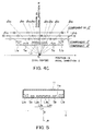
- Fig. 1 is an axial sectional view of a superconducting magnet device 1 used in a known MRI system.
- the superconducting magnet device 1 shown in Fig. 1 is provided with a vacuum vessel 10.
- the vacuum vessel 10 is formed as a cylinder having a predetermined length in a radial direction and length in axial direction and having a cylindrical bore 10a through which an axis Z can be set at the longitudinal center of the bore 10a.
- the bore 10a opens for placement of a patient, then the Z axis represents the patient's body axis passing through his head to toes.
- the magnet device 1 may provide a horizontal static magnetic field for the patient.
- the vacuum vessel 10 has a liquid helium container 11 coaxially disposed inside the vessel 10.
- the liquid helium container 11 made of stainless steel, is also constructed into a cylindrical form having predetermined radial and axial lengths.
- the liquid helium container 11 is connected to a port 12 through which liquid helium can be supplied.
- a double-walled heat shield composed of thermal shield plates 13a and 13b is disposed between the liquid helium container 11 and the vacuum vessel 10.
- the thermal shield plates 13a and 13b are cooled by a compact refrigerator 14 so as to minimize evaporation of the liquid helium.
- a magnetic shield 15 for reducing any environmental influence of the magnetic field generated by the device 1 is disposed outside the vacuum vessel 10.
- the liquid helium container 11 has main coils L1a, Lc and L1b and sub-coils Sa and Sb individually wound around the inner surface of the inside wall 11a of the container 11, predetermined distances apart in the axial direction one another.
- the inside wall 11a serves as a reel means of the present invention.
- All the main coils L1a, Lc and L1b constitute a main coil assembly and the two sub-coils Sa and Sb constitute a sub-coil assembly.
- the sub-coils Sa and Sb are disposed at axially inner positions which are next to the axial outermost main coils L1a and L1b, respectively. Namely, the sub-coil Sa is disposed at a predetermined position between the main coils L1a and Lc in Fig. 1, while the sub-coil Sb is disposed at a predetermined position between the main coils L1b and Lc in Fig. 1.
- Each of the main and sub-coils L1a, Lc, L1b, Sa and Sb is made from superconducting material such as an alloy of Nb3 Sn or Nb-Ti.
- Fig. 2 shows an electrical circuit of the superconducting magnet device 1 shown in Fig. 1. All the coils including the main coils L1a,Lc and L1b and sub-coils Sa and Sb are connected in series in the liquid helium container 11. However, the connecting direction of the sub-coils Sa and Sb is reversed against the main coils L1a, Lc, and L1b. All of the series-connected coils are then connected to a DC power supply 16. Accordingly, the direction of electric current passing through the sub-coils Sa and Sb are set to be opposite against that of the main coils L1a, Lc and L1b.
- the DC power supply 16 can be disconnected by the permanent current switch 18 after all of the coils have been put to a permanent current state.
- the protective resistance 17 can absorb energy generated when the superconducting coils, that is, L1a, Lc, L1b, Sa and Sb are quenched into an ordinary conductive state.
- Bo represents a basic magnetic field contributing to the static magnetic field and a, b and c represent coefficients of high order variables Z2 , Z4 and Z6 which are all errror terms. The higher the order of the variable Z becomes the smaller the coefficients are.
- Higher order terms having the eighth (8th) or more are omitted in Fig. 3.
- Fig. 3 shows that components of Z2 , Z4 and Z6 become zero at positions indicated by solid lines, respectively, one-dotted lines and dotted lines, thus their values are inverted between positive and negative over those lines expressed as boundaries.
- the sub-coils Sa and Sb are adopted in this embodiment according to the present invention. As shown in Fig. 4C, the sub-coils Sa and Sb are placed in the negative value region with regard to Z4 between the main coils Lc and L1a, L1b. Since an electric current is given to the sub-coils Sa and Sb, in an opposite direction to that of the main coils L1a, Lc and L1b, the axial magnetic component of Z4 produced by the sub-coils Sa and Sb may contribute to the positive value, with the result that predetermined cancellation of Z4 term from a negative value to zero is carried out.
- the axial positions of the sub-coils Sa and Sb are arranged so that the above cancellation properly works for Z2 and Z6 terms as well as Z4 term.
- the whole error terms of Z2 , Z4 and Z6 can be negligible. Therefore, when the axial length of the magnet device 10 is shortened, highly uniform magnetic field as the diagnostic space can be formed in the central part within the cylindrical bore 10a.
- one of the main coils, Lc which is positioned along the central part in the axial direction Z, is made up of four small-width coils L2a, L3a, L3b and L2b, as shown in Fig. 5.
- FIG. 5 For coil location shown in Fig. 5, an example of the current density distribution of the superconducting main coils L1a, L2a, L3a, L3b, L2b and L1b and sub-coils Sa and Sb is illustrated as a distribution curve CVb in Fig. 6.
- a distribution curve CVa shows a conventional magnet device which has a considerably large axial length. In that case, all the main coils are supplied with currents of positive (+) polarity. As seen from Fig. 6, for the conventional magnet, the current density is so determined that coils closer to both axial ends receive greater current density than coils near the axial center. Such current density distribution was intended for uniformalizing the magnetic field as the diagnostic space and expanding the uniform magnetic field, considering that the level of the magnetic field decreases as the distance from the axial center increases in the diagnostic space.
- the distribution curve CVb can be obtained for the coil location in which the axial length is reduced. It will be seen that the second points from both the end points on the distribution curve CVb, which correspond to the sub-coils Sa and Sb, are supplied with currents of negative (-) polarity, thus the sub-coils Sa and Sb being excited in reverse polarity. It is, therefore, possible to obtain a uniform high magnetic field intensity by the employing reverse excitation coils.
- the distribution curves CVa and CVb here are based on calculations conducted on assumptions that the size of diagnostic space, as well as the error in the space, is unchanged.
- Fig. 7 represents an example of magnetomotive forces of all the coils L1a, L2a, L3a, L3b, L2b, L1b, Sa and Sb according to the current density distribution in Fig. 6.
- the total magnetomotive force is 632 (KAT), while the central magnetic field is 0.35 (tesla).
- the magnetomotive force of the sub-coils Sa and Sb is 52.9 (KAT) which amounts to about 8.4 % of the total magnetomotive force.
- the sub-coils Sa and Sb consume only a small fraction of the total electric energy supplied by the DC power supply 16, thus holding high strength of the magnetic field in the diagnostic space as well as being energy-saving.
- the strength of the magnetic field therein can be increased by supplying much current into the coils.
- Fig. 9 shows a schematic view of coil arrangement of a second embodiment of the present invention.
- a main coil assembly consisting of five main coils L1a, L2a, Lc, L2b and L1b and a sub-coil assembly consisting of four sub-coils S1a, S2a, S2b and S1b.
- the sub-coils S1a and S1b constitute one pair and the sub-coils S2a and S2b constitute one pair, thus two pairs in all.
- the main coils L1a, L2a, Lc, L2b and L1b and the sub-coils S1a, S2a, S2b and S1b are alternately wound, without overlap, along a liquid helium container 11. And the sub-coils S1a, S2a, S2b and S1b are disposed so as to eliminate properly axial error components of a magnetic field produced by the main coils L1a, L2a, Lc, L2b and L1b by employing the same algorithm as that of the first embodiment.
- the above superconducting magnet device of the second embodiment can operates similarly to that of the first embodiment.
- two pairs of sub-coils facilitate higher accuracy, compared with one-pair sub-coil system, in eliminating the axial error components of the magnetic field.
- the magnet devices have been each described as a superconducting magnet device.
- other magnet devices such as a permanent magnet device and a normal conducting magnet device, are also applicable in the present invention.
Abstract
Description
- The present invention relates to a magnet device for generating a static magnetic field in magnetic resonance imaging (MRI), and more particularly to the magnet device, provided with a main coil assembly and a sub-coil assembly for shimming the static magnetic field created by the main coil assembly, which generates a horizontal magnetic field in which magnetic lines of force pass along a patient's body axis.
- In magnetic resonance imaging, there is provided a magnet device for generating a static magnetic field, whereby atomic nuclei of a patient body align themselves with the static field. For high resolution and non-distortion of images produced, the static magnetic field is needed, as one of the requirements for MRI, so as to have a highly uniform magnetic field providing a practical diagnostic space. The diagnostic space having high uniformity of magnetic flux can be accomplished by adopting shim coils.
- U.S.Pat.No.4,506,247 discloses even and odd pairs of axisymmetric correction coils (i.e. shim coil assembly) disposed on a cylindrical coil form at specified longitudinal positions without overlap. Intention of these coil pairs is to provide a correction field for a magnet employed in MRI systems. The correction is given by selecting properly the locations of the coils on the cylindrical coil form which is disposed coaxially with a main magnet device such as a permanent magnet device and a superconducting magnet device.
- However, applying the above correction coil system to a main magnet device will result in the increase of the size in the radial direction of the device, for the cylindrical coil form must be installed separetely from and coaxially with the main magnet. Moreover, assembling of the whole magnet device would be cumbersome. Further, two power units for the main coils and correction coils are needed.
- Japanese Patent Laid open No. 62-293704 also discloses a shimming mechanism for a vertical magnetic field in which magnetic lines of force pass through a patient's body from his front to his back or contrary. The above shimming mechanism adopts at least one pair of ring-like sub-coils, which is disposed, together with main coils producing a main magnetic field, within a fixed angle range with respect to the centeral point of the static magnetic field. The sub-coils are to receive electric current permitting them to generate a reverse magnetic field to the main magnetic field in order to acquire a uniformity of the diagnostic space.
- Even in the magnet device generating the horizontal magnetic field, it is desirable to create a large diagnostic space which necessarily leads to a far distance between the coils of a main coil pair. Then, when the device of generating the horizontal magnetic field utilizes the above shimming mechanism, the device will increase its size in the axial direction, because the sub-coils must exist in the main coil assembly. Besides, accomodating the main coils and sub-coils within the predetermined angle region with respect to the central point will result in a bulky size in its radial direction.
- It is also required for the magnet device to provide a large diagnostic space having a high strength uniform magnetic field. A patient may be troubled with claustrophobia due to a small, tight diagnostic space during the examination. To avoid such mental pain, the size of the magnet device will have to be increased in both the axial and radial directions, which is undesirable. Especially, in a superconducting magnet device which is desirable for generating a high strength of magnetism, a high-strength, high-uniform spherical diagnostic space of 30 to 50 cm diameter would lead to a noticeably elongated axial form for keeping a less-error axial region as long as possible.
- Accordingly, it is a primary object of the present invention to provide a magnet device which can be produced into a compact form in both the axial and radial directions and which can generate a uniform diagnostic space in a static magnetic field.
- It is another object of the present invention to provide a magnet device generating a highly uniform diagnostic space large enough to avoid patient's mental pain.
- It is further object of the present invention to provide a magnet device applicable at its best when the horizontal magnetic field is required as a main magnetic field.
- It is still further object of the present invention to provide a magnet device applied desirably to a superconducting magnet device.
- These and other objects can be achieved according to the present invention, in one aspect by providing, a magnet device of a magnetic resonance imaging system which has a cylindrical space wherein a central point is determined in an axial and a radial directions of the cylindrical space and which generates a static magnetic field in the cylindrical space, said magnet device comprising a reel element for forming said cylindrical space therein; a main coil assembly including a plurality of ring-like main coils wound around said reel element at axial positions of the reel element, the axial positions being symmetric with respect to said central point; a sub-coil assembly including at least one pair of ring-like sub-coils wound around said reel element; and a coil driving element for giving said main coils magnetomotive forces to make the main coils generate a main magnetic field along a predetermined axial direction in said cylindrical space and for giving said sub-coils magnetomotive forces to make the sub-coils generate a magnetic field inverse to the main magnetic field, wherein said sub-coils are wound around said reel element at axial positions of the reel element, the axial positions being at axially inner positions in said main coil assembly.
- Preferably, said sub-coils are disposed so as to suppress high order components of a series expansion for an axial component of said main magnetic field in the cylindrical space.
- It is preferred that said main coil assembly comprises three or more main coils and said sub-coil assembly comprises one pair of sub-coils, and said sub-coils are each disposed next to axial outermost main coils of the main coil assembly.
- It is also preferred that said main coil assembly comprises five or more main coils and said sub-coil assembly comprises two pairs of sub-coils, and one pair of said two pairs of sub-coils are each disposed between first axial outer main coils and second axial outer main coils of the main coil assembly and another pair of said two pairs of sub-coils are each disposed between the first axial outer main coils and third axial outer main coils of the main coil assembly.
- The location of sub-coils into the main coil assembly can cancel error components of the main magnetic field for the magnet device having axially and radially reduced lengths. As a result, the magnet device can be made into an axially compact form, generating a highly uniform magnetic field as a diagnostic space.
- It is also preferred that all of said main coils and sub-coils are electrically connected in series, said sub-coils being oppositely wound against the main coils. Said coil driving element comprises one electric power, the electric power being electrically connected in series to said all of the main coils and sub-coils.
- As a result, only one electric power is enough to drive the magnet device, leading to its simplified construction as a whole.
- It is also preferred that the magnet device is applied to a superconducting magnet device provided with a liquid helium container having an inner cylindrical wall portion which serves as said reel element. Said main coils and sub-coils are wound around the inner cylindrical wall portion, the main coils and sub-coils being activated as superconducting coils therein. Thus, it is possible to make the superconducting magnet device compact with a highly uniform diagnostic space therein.
- In a further aspect according the present invention, there is provided a magnet device of a magnetic resonance imaging system, further, wherein said axial positions and magnetomotive forces of the main coils and sub-coils are adjusted so as to form a uniform static magnetic field produced together by the main coils and sub-coils as a diagnostic space into a shape in which an axis extending in said radial direction is longer than an axis extending in said axial direction. Further, said diagnostic space is formed into an ellipsoidal shape in section or an ellipsoidal shape in section having partially distorted portions.
- As a result, in addition to magnetically uniformity of a diagnostic space, the magnet device can make the diagnostic space so that the space is able to give a patient widened feeling and to relax the patient therein.
- The accompanying drawings which are incorporated in and constitute a part of this specification, illustrate embodiments of the present invention and, together with the description, serve to explain the principles of the present invention; in which:
- Fig. 1 is an axially-cut sectional view of an upper half part of a superconducting magnet device, in which main and sub-coil assemblies are incorporated, according to a first embodiment of the present invention;
- Fig. 2 is a circuit diagram showing a manner in which the coil assemblies shown in Fig. 1 are connected;
- Fig. 3 is a graphical representation showing behavior of axial components, corresponding to error terms, of a static magnetic field;
- Figs. 4A to 4C are graphical representations showing necessity of the sub-coil assembly;
- Fig. 5 is a partial sectional view representing a practical coil arrangement for the main coil assembly;
- Fig. 6 is an illustration of pattern of current density distribution in the first embodiment;
- Fig. 7 is a table showing levels of magnetomotive forces by the main and sub-coil assemblies;
- Fig. 8 is an illustration of distribution pattern of equi-magnetic field lines in and around a diagnostic space; and
- Fig. 9 is an axially-cut partial sectional view representing a further coil arrangement according to a second embodiment of the present invention.
- A first embodiment of a magnet device in accordane with the present invention will now be described with reference to Fig. 1 to Fig. 4C. In this embodiment, the magnet device is constructed as a superconducting magnet device.
- Fig. 1 is an axial sectional view of a
superconducting magnet device 1 used in a known MRI system. Thesuperconducting magnet device 1 shown in Fig. 1 is provided with avacuum vessel 10. Thevacuum vessel 10 is formed as a cylinder having a predetermined length in a radial direction and length in axial direction and having a cylindrical bore 10a through which an axis Z can be set at the longitudinal center of the bore 10a. The bore 10a opens for placement of a patient, then the Z axis represents the patient's body axis passing through his head to toes. Themagnet device 1 may provide a horizontal static magnetic field for the patient. - The
vacuum vessel 10 has aliquid helium container 11 coaxially disposed inside thevessel 10. - The
liquid helium container 11, made of stainless steel, is also constructed into a cylindrical form having predetermined radial and axial lengths. Theliquid helium container 11 is connected to aport 12 through which liquid helium can be supplied. - A double-walled heat shield composed of
thermal shield plates 13a and 13b is disposed between theliquid helium container 11 and thevacuum vessel 10. Thethermal shield plates 13a and 13b are cooled by acompact refrigerator 14 so as to minimize evaporation of the liquid helium. Amagnetic shield 15 for reducing any environmental influence of the magnetic field generated by thedevice 1 is disposed outside thevacuum vessel 10. - The
liquid helium container 11 has main coils L1a, Lc and L1b and sub-coils Sa and Sb individually wound around the inner surface of theinside wall 11a of thecontainer 11, predetermined distances apart in the axial direction one another. Theinside wall 11a serves as a reel means of the present invention. All the main coils L1a, Lc and L1b constitute a main coil assembly and the two sub-coils Sa and Sb constitute a sub-coil assembly. In addition, all of the main and sub coils mentioned above are positioned so as to be symmetric with respect to both the axis Z and an imaginary midplane R right to the axis Z at the center O (i.e. Z=0: origin) of this coil system. - The sub-coils Sa and Sb are disposed at axially inner positions which are next to the axial outermost main coils L1a and L1b, respectively. Namely, the sub-coil Sa is disposed at a predetermined position between the main coils L1a and Lc in Fig. 1, while the sub-coil Sb is disposed at a predetermined position between the main coils L1b and Lc in Fig. 1.
- Each of the main and sub-coils L1a, Lc, L1b, Sa and Sb is made from superconducting material such as an alloy of Nb₃ Sn or Nb-Ti.
- Fig. 2 shows an electrical circuit of the
superconducting magnet device 1 shown in Fig. 1. All the coils including the main coils L1a,Lc and L1b and sub-coils Sa and Sb are connected in series in theliquid helium container 11. However, the connecting direction of the sub-coils Sa and Sb is reversed against the main coils L1a, Lc, and L1b. All of the series-connected coils are then connected to aDC power supply 16. Accordingly, the direction of electric current passing through the sub-coils Sa and Sb are set to be opposite against that of the main coils L1a, Lc and L1b. - In the
liquid helium container 11, there is provided aprotective resistance 17 and a permanentcurrent switch 18, both of which are in parallel connected to the series-connected coils. TheDC power supply 16 can be disconnected by the permanentcurrent switch 18 after all of the coils have been put to a permanent current state. Theprotective resistance 17 can absorb energy generated when the superconducting coils, that is, L1a, Lc, L1b, Sa and Sb are quenched into an ordinary conductive state. - Then, the reason why the sub-coils Sa and Sb should be disposed inside the main coil assembly will be explained with reference to Figs. 3 and 4A to 4C.
- In MRI systems, when several pairs of annular coils are placed face to face at positions which are symmetric on the Z axis, and electric currents of the same direction are supplied into those annular coils respectively, it is known that an axial component of a magnetic field B in a diagnostic space DS by those circular electric currents is given by the following series expansion accompanying even higher terms only.

- In the above series expansion, Bo represents a basic magnetic field contributing to the static magnetic field and a, b and c represent coefficients of high order variables Z² , Z⁴ and Z⁶ which are all errror terms. The higher the order of the variable Z becomes the smaller the coefficients are.
- The error terms aZ² , bZ⁴ and cZ⁶ in the above series expansion can be shown schematically in a coordinate consisting of both Z axis and R axis representing the radius at Z=O, like shown in Fig. 3. Higher order terms having the eighth (8th) or more are omitted in Fig. 3.
- Fig. 3 shows that components of Z² , Z⁴ and Z⁶ become zero at positions indicated by solid lines, respectively, one-dotted lines and dotted lines, thus their values are inverted between positive and negative over those lines expressed as boundaries.
- Now, let's assume that a uniform magnetic field is maintained for a certain coil location shown in Fig. 4A. That is, the central main coil Lc almost reaches the one-dotted line boundary ( Z⁴ =O) from the negative value region of Z⁴ , while the right-side main coil L1b exists in the positive value region of Z⁴ .
- Then, it is assumed that, like shown in Fig. 4B, the main coil Lc is contracted in the axial direction (Z axis) and the main coil L1b is moved for the axial center for reducing axial length of the
whole magnet device 1. This reduction of the axial length causes an axial component of the magnetic field with respect to the Z⁴ term to be more negative and less positive, with the result that a negative bias of the value would arise and the uniformity of the magnetic field would be deteriorated due to the imbalanced error term Z⁴ . - The same explanation can be applied to other error terms Z² and Z⁶ .
- It is revealed that, from the above explanation, the relocation only of the main coils L1a, Lc and L1b can not achieve a reduced axial length and a high uniformity of magnetic field.
- However, the sub-coils Sa and Sb are adopted in this embodiment according to the present invention. As shown in Fig. 4C, the sub-coils Sa and Sb are placed in the negative value region with regard to Z⁴ between the main coils Lc and L1a, L1b. Since an electric current is given to the sub-coils Sa and Sb, in an opposite direction to that of the main coils L1a, Lc and L1b, the axial magnetic component of Z⁴ produced by the sub-coils Sa and Sb may contribute to the positive value, with the result that predetermined cancellation of Z⁴ term from a negative value to zero is carried out.
- The axial positions of the sub-coils Sa and Sb are arranged so that the above cancellation properly works for Z² and Z⁶ terms as well as Z⁴ term. The whole error terms of Z² , Z⁴ and Z⁶ can be negligible. Therefore, when the axial length of the
magnet device 10 is shortened, highly uniform magnetic field as the diagnostic space can be formed in the central part within the cylindrical bore 10a. - In addition to the shortened axial length, it is possible to reduce the radius of the
device 1 because all the coils L1a, Lc, L1b, Sa and Sb are wound without overlap. This coil winding enables theentire device 1 to be compact. A separate cylindrical coil form is not necessary to be installed, so that the whole structure can be simplified a great deal. - Practically, one of the main coils, Lc, which is positioned along the central part in the axial direction Z, is made up of four small-width coils L2a, L3a, L3b and L2b, as shown in Fig. 5.
- For coil location shown in Fig. 5, an example of the current density distribution of the superconducting main coils L1a, L2a, L3a, L3b, L2b and L1b and sub-coils Sa and Sb is illustrated as a distribution curve CVb in Fig. 6.
- Referring to Fig. 6, a distribution curve CVa shows a conventional magnet device which has a considerably large axial length. In that case, all the main coils are supplied with currents of positive (+) polarity. As seen from Fig. 6, for the conventional magnet, the current density is so determined that coils closer to both axial ends receive greater current density than coils near the axial center. Such current density distribution was intended for uniformalizing the magnetic field as the diagnostic space and expanding the uniform magnetic field, considering that the level of the magnetic field decreases as the distance from the axial center increases in the diagnostic space.
- In the present embodiment, however, the distribution curve CVb can be obtained for the coil location in which the axial length is reduced. It will be seen that the second points from both the end points on the distribution curve CVb, which correspond to the sub-coils Sa and Sb, are supplied with currents of negative (-) polarity, thus the sub-coils Sa and Sb being excited in reverse polarity. It is, therefore, possible to obtain a uniform high magnetic field intensity by the employing reverse excitation coils.
- The distribution curves CVa and CVb here are based on calculations conducted on assumptions that the size of diagnostic space, as well as the error in the space, is unchanged.
- Furthermore, Fig. 7 represents an example of magnetomotive forces of all the coils L1a, L2a, L3a, L3b, L2b, L1b, Sa and Sb according to the current density distribution in Fig. 6. The total magnetomotive force is 632 (KAT), while the central magnetic field is 0.35 (tesla). The magnetomotive force of the sub-coils Sa and Sb is 52.9 (KAT) which amounts to about 8.4 % of the total magnetomotive force. Namely, the sub-coils Sa and Sb consume only a small fraction of the total electric energy supplied by the
DC power supply 16, thus holding high strength of the magnetic field in the diagnostic space as well as being energy-saving. In addition, the strength of the magnetic field therein can be increased by supplying much current into the coils. - On the other hand, when the aforementioned coil location and magnetomotive forces are designated, an equi-magnetic field distribution in and around the diagnostic space is found to be as shown in Fig. 8. Symbols CVe, CVf and CVg in Fig. 8, respectively, show levels of erros of -1 ppm, -3 ppm and -5 ppm with respect to the central magnetic field. Furthermore, symbols CVh and CVi in Fig. 8, respectively, show levels of erros of +1 ppm and +3 ppm. As a range of -5 ppm to +5 ppm may well be designated for uniformality of a diagnosic space, a partial distribution curve CVc can be drawn in Fig. 8. On the distribution curve CVc, since the error in the radial direction at the center (Z=0) is smaller than the error in the axial direction, it is possible to provide the ellipsoidal diagnostic space DS (refer to Fig. 1), which has a longer axis extending in the radial direction R than that in the axial direction Z. In Fig. 8, a partially-circular distribution curve CVd, which provides a conventional spherical diagnostic space, is imaginarily illustrated for reference.
- It is thus possible to obtain a radially expanded space for the diagnostic space DS, whereby the ellipsoidal diagnostic space gives a patient relieved feeling from claustrophobia due to a small diagnostic space.
- Fig. 9 shows a schematic view of coil arrangement of a second embodiment of the present invention. According to structure in Fig. 9, there is provided a main coil assembly consisting of five main coils L1a, L2a, Lc, L2b and L1b and a sub-coil assembly consisting of four sub-coils S1a, S2a, S2b and S1b. The sub-coils S1a and S1b constitute one pair and the sub-coils S2a and S2b constitute one pair, thus two pairs in all. The main coils L1a, L2a, Lc, L2b and L1b and the sub-coils S1a, S2a, S2b and S1b are alternately wound, without overlap, along a
liquid helium container 11. And the sub-coils S1a, S2a, S2b and S1b are disposed so as to eliminate properly axial error components of a magnetic field produced by the main coils L1a, L2a, Lc, L2b and L1b by employing the same algorithm as that of the first embodiment. - As a result, the above superconducting magnet device of the second embodiment can operates similarly to that of the first embodiment. Particularly, two pairs of sub-coils facilitate higher accuracy, compared with one-pair sub-coil system, in eliminating the axial error components of the magnetic field.
- In the aforementioned embodiments, the magnet devices have been each described as a superconducting magnet device. However, other magnet devices, such as a permanent magnet device and a normal conducting magnet device, are also applicable in the present invention. Furthermore, there may be provided two separate DC power units for the main coil assembly and sub-coil assembly, if those main coils and sub-coils would not be connected in series.
Claims (13)
- A magnet device of a magnetic resonance imaging system which has a cylindrical space wherein a central point is determined in an axial and a radial directions of the cylindrical space and which generates a static magnetic field in the cylindrical space, said magnet device comprising:
a reel means for forming said cylindrical space therein;
a main coil assembly including a plurality of ring-like main coils wound around said reel means at axial positions of the reel means, the axial positions being symmetric with respect to said central point;
a sub-coil assembly including at least one pair of ring-like sub-coils wound around said reel means; and
a coil driving means for giving said main coils magnetomotive forces to make the main coils generate a main magnetic field along a predetermined axial direction in said cylindrical space and for giving said sub-coils magnetomotive forces to make the sub-coils generate a magnetic field inverse to the main magnetic field,
wherein said sub-coils are wound around said reel means at axial positions of the reel means, the axial positions being at axially inner positions in said main coil assembly. - A magnet device as claimed in claim 1, wherein said sub-coils are disposed so as to suppress high order components of a series expansion for an axial component of said main magnetic field in the cylindrical space.
- A magnet device as claimed in claim 2, wherein said main coil assembly comprises three or more main coils and said sub-coil assembly comprises one pair of sub-coils.
- A magnet device as claimed in claim 3, wherein said sub-coils are each disposed next to axial outermost main coils of the main coil assembly.
- A magnet device as claimed in claim 2, wherein said main coil assembly comprises five or more main coils and said sub-coil assembly comprises two pairs of sub-coils.
- A magnet device as claimed in claim 5, wherein one pair of said two pairs of sub-coils are each disposed between first axial outer main coils and second axial outer main coils of the main coil assembly and another pair of said two pairs of sub-coils are each disposed between the first axial outer main coils and third axial outer main coils of the main coil assembly.
- A magnet device as claimed in claim 1, wherein all of said main coils and sub-coils are electrically connected in series, said sub-coils being oppositely wound against the main coils.
- A magnet device as shown in claim 7, wherein said coil driving means comprises one electric power, the electric power being electrically connected in series to said all of the main coils and sub-coils.
- A magnet device as claimed in claim 1, wherein the magnet device is applied to a superconducting magnet device provided with a liquid helium container having an inner cylindrical wall portion which serves as said reel means.
- A magnet device as claimed in claim 9, wherein said main coils and sub-coils are wound around the inner cylindrical wall portion, the main coils and sub-coils being activated as superconducting coils therein.
- A magnet device of a magnetic resonance imaging system which has a cylindrical space wherein a central point is determined in an axial and a radial directions of the cylindrical space and which generates a static magnetic field in the cylindrical space, said said device comprising:
a reel means for forming said cylindrical space therein;
a main coil assembly including a plurality of ring-like main coils wound around said reel means at axial positions of the reel means, the axial positions being symmetric with respect to said central point;
a sub-coil assembly including at least one pair of ring-like sub-coils wound around said reel means; and
a coil driving means for giving said main coils magnetomotive forces to make the main coils generate a main magnetic field along a predetermined axial direction in said cylindrical space and for giving said sub-coils magnetomotive forces to make the sub-coils generate a magnetic field inverse to the main magnetic field,
wherein said sub-coils are wound around said reel means at axial positions of the reel means, the axial positions being at axially inner positions in said main coil assembly, and said axial positions and magnetomotive forces of the main coils and sub-coils are adjusted so as to form a uniform static magnetic field produced together by the main coils and sub-coils as a diagnostic space into a shape in which an axis extending in said radial direction is longer than an axis extending in said axial direction. - A magnet device as claimed in claim 11, wherein said diagnostic space is formed into an ellipsoidal shape in section.
- A magnet device as claimed in claim 11, wherein said diagnostic space is formed into an ellipsoidal shape in section having partially distorted portions.
Applications Claiming Priority (2)
| Application Number | Priority Date | Filing Date | Title |
|---|---|---|---|
| JP3006486A JPH04240440A (en) | 1991-01-23 | 1991-01-23 | Magnet for mri apparatus |
| JP6486/91 | 1991-01-23 |
Publications (2)
| Publication Number | Publication Date |
|---|---|
| EP0496368A1 true EP0496368A1 (en) | 1992-07-29 |
| EP0496368B1 EP0496368B1 (en) | 1996-11-13 |
Family
ID=11639809
Family Applications (1)
| Application Number | Title | Priority Date | Filing Date |
|---|---|---|---|
| EP92100993A Expired - Lifetime EP0496368B1 (en) | 1991-01-23 | 1992-01-22 | Magnetic device for generating static magnetic field in MRI |
Country Status (4)
| Country | Link |
|---|---|
| US (1) | US5343182A (en) |
| EP (1) | EP0496368B1 (en) |
| JP (1) | JPH04240440A (en) |
| DE (1) | DE69215114T2 (en) |
Cited By (5)
| Publication number | Priority date | Publication date | Assignee | Title |
|---|---|---|---|---|
| EP0535735A1 (en) * | 1991-10-03 | 1993-04-07 | Koninklijke Philips Electronics N.V. | Magnetic resonance apparatus comprising a shielded magnet |
| EP0826978A1 (en) * | 1996-08-26 | 1998-03-04 | General Electric Company | Closed MRI magnet having compact design |
| EP1036541A1 (en) * | 1997-12-01 | 2000-09-20 | Hitachi Medical Corporation | Magnet apparatus and mri apparatus |
| WO2005043183A1 (en) * | 2003-10-30 | 2005-05-12 | Koninklijke Philips Electronics, N.V. | Mri system with variable field of view magnet |
| WO2009001084A1 (en) * | 2007-06-26 | 2008-12-31 | Oxford Instruments Plc | Magnet system for use in magnetic resonance imaging |
Families Citing this family (11)
| Publication number | Priority date | Publication date | Assignee | Title |
|---|---|---|---|---|
| JP3019683B2 (en) * | 1993-09-20 | 2000-03-13 | 株式会社日立製作所 | Permanent current switch and superconducting magnet system |
| GB2298282B (en) * | 1995-02-23 | 1999-08-25 | Elscint Ltd | Quench protection for actively shielded magnets |
| US5818319A (en) * | 1995-12-21 | 1998-10-06 | The University Of Queensland | Magnets for magnetic resonance systems |
| GB2309305B (en) * | 1996-01-19 | 2000-05-31 | Oxford Magnet Tech | Improvements in or relating to MRI magnets |
| US5721523A (en) * | 1996-08-26 | 1998-02-24 | General Electric Company | Compact MRI superconducting magnet |
| KR20020070984A (en) * | 2000-09-26 | 2002-09-11 | 코닌클리케 필립스 일렉트로닉스 엔.브이. | Vertical field type MRI apparatus with a conical cavity situated in the main magnet |
| AU2007308759B2 (en) * | 2006-10-27 | 2011-05-12 | Nmr Holdings No. 2 Pty Limited | Magnets for use in magnetic resonance imaging |
| US10429461B2 (en) * | 2013-01-16 | 2019-10-01 | Hitachi, Ltd. | Magnetic resonance imaging device and timing misalignment detection method thereof |
| JP6138600B2 (en) * | 2013-06-12 | 2017-05-31 | ジャパンスーパーコンダクタテクノロジー株式会社 | Magnetic field generator |
| DE102014217250A1 (en) * | 2014-08-29 | 2016-03-03 | Siemens Aktiengesellschaft | Superconducting coil device with switchable conductor section and method for switching |
| EP3896472A1 (en) * | 2020-04-14 | 2021-10-20 | Siemens Healthcare GmbH | Device and method for nuclear magnet resonance spectroscopy |
Citations (6)
| Publication number | Priority date | Publication date | Assignee | Title |
|---|---|---|---|---|
| US4506247A (en) * | 1984-05-23 | 1985-03-19 | General Electric Company | Axisymmetric correction coil system for NMR magnets |
| EP0167243A2 (en) * | 1984-07-06 | 1986-01-08 | The Board Of Trustees Of The Leland Stanford Junior University | Magnetic structure |
| EP0236789A1 (en) * | 1986-02-28 | 1987-09-16 | Siemens Aktiengesellschaft | Non-orthogonal Shim coil system for the correction of magnetic-field inhomogeneities in nuclear magnetic resonance apparatuses |
| EP0251342A2 (en) * | 1983-11-11 | 1988-01-07 | Oxford Medical Limited | Magnet assembly |
| DE3829175A1 (en) * | 1987-08-29 | 1989-03-16 | Fuji Electric Co Ltd | COIL FOR GENERATING A HOMOGENEOUS MAGNETIC FIELD |
| EP0424600A1 (en) * | 1989-10-25 | 1991-05-02 | Kabushiki Kaisha Toshiba | Magnet apparatus for use in a magnetic resonance imaging system |
Family Cites Families (14)
| Publication number | Priority date | Publication date | Assignee | Title |
|---|---|---|---|---|
| US4385277A (en) * | 1980-01-21 | 1983-05-24 | The Oxford Instruments Group Limited | Topical nuclear magnetic resonance spectrometer and method |
| GB8410972D0 (en) * | 1984-04-30 | 1984-06-06 | Oxford Magnet Tech | Magnet assembly |
| JPS62293704A (en) * | 1986-06-13 | 1987-12-21 | Toshiba Corp | Coil device for generating uniform magnetic field |
| JPS63260116A (en) * | 1987-04-17 | 1988-10-27 | Toshiba Corp | Magnetic shield of magnetic resonance imaging apparatus |
| US4724412A (en) * | 1987-08-03 | 1988-02-09 | General Electric Company | Method of determining coil arrangement of an actively shielded magnetic resonance magnet |
| JPH01227407A (en) * | 1988-03-08 | 1989-09-11 | Toshiba Corp | Magnet for magnetic resonance imaging device |
| US5136273A (en) * | 1988-10-17 | 1992-08-04 | Kabushiki Kaisha Toshiba | Magnet apparatus for use in a magnetic resonance imaging system |
| JPH02106905A (en) * | 1988-10-17 | 1990-04-19 | Toshiba Corp | Magnet for mri device |
| DE3907927A1 (en) * | 1989-03-11 | 1990-09-20 | Bruker Analytische Messtechnik | MAGNETIC SYSTEM |
| IL90050A (en) * | 1989-04-23 | 1992-07-15 | Elscint Ltd | Integrated active shielded magnet system |
| DE3914243A1 (en) * | 1989-04-29 | 1990-10-31 | Bruker Analytische Messtechnik | MAGNETIC SYSTEM WITH SUPERCONDUCTIVE FIELD PULES |
| US5045826A (en) * | 1990-04-05 | 1991-09-03 | General Electric Company | Actively shielded magnetic resonance magnet without cryogens |
| GB9016183D0 (en) * | 1990-07-24 | 1990-09-05 | Oxford Magnet Tech | Magnet assembly |
| EP0535735A1 (en) * | 1991-10-03 | 1993-04-07 | Koninklijke Philips Electronics N.V. | Magnetic resonance apparatus comprising a shielded magnet |
-
1991
- 1991-01-23 JP JP3006486A patent/JPH04240440A/en active Pending
-
1992
- 1992-01-22 EP EP92100993A patent/EP0496368B1/en not_active Expired - Lifetime
- 1992-01-22 DE DE69215114T patent/DE69215114T2/en not_active Expired - Fee Related
- 1992-01-23 US US07/824,504 patent/US5343182A/en not_active Expired - Fee Related
Patent Citations (6)
| Publication number | Priority date | Publication date | Assignee | Title |
|---|---|---|---|---|
| EP0251342A2 (en) * | 1983-11-11 | 1988-01-07 | Oxford Medical Limited | Magnet assembly |
| US4506247A (en) * | 1984-05-23 | 1985-03-19 | General Electric Company | Axisymmetric correction coil system for NMR magnets |
| EP0167243A2 (en) * | 1984-07-06 | 1986-01-08 | The Board Of Trustees Of The Leland Stanford Junior University | Magnetic structure |
| EP0236789A1 (en) * | 1986-02-28 | 1987-09-16 | Siemens Aktiengesellschaft | Non-orthogonal Shim coil system for the correction of magnetic-field inhomogeneities in nuclear magnetic resonance apparatuses |
| DE3829175A1 (en) * | 1987-08-29 | 1989-03-16 | Fuji Electric Co Ltd | COIL FOR GENERATING A HOMOGENEOUS MAGNETIC FIELD |
| EP0424600A1 (en) * | 1989-10-25 | 1991-05-02 | Kabushiki Kaisha Toshiba | Magnet apparatus for use in a magnetic resonance imaging system |
Cited By (6)
| Publication number | Priority date | Publication date | Assignee | Title |
|---|---|---|---|---|
| EP0535735A1 (en) * | 1991-10-03 | 1993-04-07 | Koninklijke Philips Electronics N.V. | Magnetic resonance apparatus comprising a shielded magnet |
| EP0826978A1 (en) * | 1996-08-26 | 1998-03-04 | General Electric Company | Closed MRI magnet having compact design |
| EP1036541A1 (en) * | 1997-12-01 | 2000-09-20 | Hitachi Medical Corporation | Magnet apparatus and mri apparatus |
| EP1036541A4 (en) * | 1997-12-01 | 2005-11-02 | Hitachi Medical Corp | Magnet apparatus and mri apparatus |
| WO2005043183A1 (en) * | 2003-10-30 | 2005-05-12 | Koninklijke Philips Electronics, N.V. | Mri system with variable field of view magnet |
| WO2009001084A1 (en) * | 2007-06-26 | 2008-12-31 | Oxford Instruments Plc | Magnet system for use in magnetic resonance imaging |
Also Published As
| Publication number | Publication date |
|---|---|
| DE69215114D1 (en) | 1996-12-19 |
| US5343182A (en) | 1994-08-30 |
| JPH04240440A (en) | 1992-08-27 |
| EP0496368B1 (en) | 1996-11-13 |
| DE69215114T2 (en) | 1997-06-12 |
Similar Documents
| Publication | Publication Date | Title |
|---|---|---|
| EP0496368B1 (en) | Magnetic device for generating static magnetic field in MRI | |
| US11726155B2 (en) | B0 magnet methods and apparatus for a magnetic resonance imaging system | |
| EP0629873B1 (en) | Combined self shielded gradient coil and shimset | |
| JP2581536B2 (en) | Magnet device and method of using the same | |
| US6479999B1 (en) | Efficiently shielded MRI gradient coil with discretely or continuously variable field of view | |
| EP0676647A1 (en) | Open MRI magnet | |
| US4506247A (en) | Axisymmetric correction coil system for NMR magnets | |
| US20020050895A1 (en) | Magnetic apparatus for MRI | |
| US5721523A (en) | Compact MRI superconducting magnet | |
| US20100060282A1 (en) | Three-dimensional asymmetric transverse gradient coils | |
| US5574417A (en) | Open MRI magnet with homogeneous imaging volume | |
| GB2354328A (en) | Passive shimming method | |
| EP0152554B1 (en) | Intentionally non-orthogonal correction coils for high-homogeneity magnets | |
| US6351123B1 (en) | Gradient coil system for a magnetic resonance tomography apparatus | |
| JP5322780B2 (en) | Superconducting magnet device | |
| US5568110A (en) | Closed MRI magnet having reduced length | |
| US5568102A (en) | Closed superconductive magnet with homogeneous imaging volume | |
| JPH07502925A (en) | Local transverse gradient coil | |
| US4755755A (en) | Compact transverse magnetic gradient coils and dimensioning method therefor | |
| US20070114997A1 (en) | Systems, methods and apparatus for a partially elongated field of view in a magnetic resonance imaging system | |
| US4799017A (en) | Background field magnet for image generating devices using nuclear spin resonance | |
| JP3715442B2 (en) | Permanent current superconducting magnet system | |
| US5296812A (en) | Superconducting magnet assembly for MRI and MRI diagnostic apparatus | |
| EP1576382B1 (en) | Self-shielded gradient coil arrangements with minimised risk of partial discharge | |
| US7436179B2 (en) | Magnet device |
Legal Events
| Date | Code | Title | Description |
|---|---|---|---|
| PUAI | Public reference made under article 153(3) epc to a published international application that has entered the european phase |
Free format text: ORIGINAL CODE: 0009012 |
|
| 17P | Request for examination filed |
Effective date: 19920122 |
|
| AK | Designated contracting states |
Kind code of ref document: A1 Designated state(s): DE GB NL |
|
| GRAG | Despatch of communication of intention to grant |
Free format text: ORIGINAL CODE: EPIDOS AGRA |
|
| 17Q | First examination report despatched |
Effective date: 19960205 |
|
| GRAH | Despatch of communication of intention to grant a patent |
Free format text: ORIGINAL CODE: EPIDOS IGRA |
|
| GRAH | Despatch of communication of intention to grant a patent |
Free format text: ORIGINAL CODE: EPIDOS IGRA |
|
| GRAA | (expected) grant |
Free format text: ORIGINAL CODE: 0009210 |
|
| AK | Designated contracting states |
Kind code of ref document: B1 Designated state(s): DE GB NL |
|
| REF | Corresponds to: |
Ref document number: 69215114 Country of ref document: DE Date of ref document: 19961219 |
|
| PLBE | No opposition filed within time limit |
Free format text: ORIGINAL CODE: 0009261 |
|
| STAA | Information on the status of an ep patent application or granted ep patent |
Free format text: STATUS: NO OPPOSITION FILED WITHIN TIME LIMIT |
|
| 26N | No opposition filed | ||
| REG | Reference to a national code |
Ref country code: GB Ref legal event code: IF02 |
|
| PGFP | Annual fee paid to national office [announced via postgrant information from national office to epo] |
Ref country code: NL Payment date: 20050103 Year of fee payment: 14 |
|
| PGFP | Annual fee paid to national office [announced via postgrant information from national office to epo] |
Ref country code: GB Payment date: 20050119 Year of fee payment: 14 |
|
| PGFP | Annual fee paid to national office [announced via postgrant information from national office to epo] |
Ref country code: DE Payment date: 20050120 Year of fee payment: 14 |
|
| PG25 | Lapsed in a contracting state [announced via postgrant information from national office to epo] |
Ref country code: GB Free format text: LAPSE BECAUSE OF NON-PAYMENT OF DUE FEES Effective date: 20060122 |
|
| PG25 | Lapsed in a contracting state [announced via postgrant information from national office to epo] |
Ref country code: NL Free format text: LAPSE BECAUSE OF NON-PAYMENT OF DUE FEES Effective date: 20060801 Ref country code: DE Free format text: LAPSE BECAUSE OF NON-PAYMENT OF DUE FEES Effective date: 20060801 |
|
| GBPC | Gb: european patent ceased through non-payment of renewal fee |
Effective date: 20060122 |
|
| NLV4 | Nl: lapsed or anulled due to non-payment of the annual fee |
Effective date: 20060801 |