EP0496304A1 - Fluid-dispensing instruments having barbed nib holders - Google Patents
Fluid-dispensing instruments having barbed nib holders Download PDFInfo
- Publication number
- EP0496304A1 EP0496304A1 EP92100780A EP92100780A EP0496304A1 EP 0496304 A1 EP0496304 A1 EP 0496304A1 EP 92100780 A EP92100780 A EP 92100780A EP 92100780 A EP92100780 A EP 92100780A EP 0496304 A1 EP0496304 A1 EP 0496304A1
- Authority
- EP
- European Patent Office
- Prior art keywords
- nib
- wall
- fluid dispensing
- holder
- dispensing instrument
- Prior art date
- Legal status (The legal status is an assumption and is not a legal conclusion. Google has not performed a legal analysis and makes no representation as to the accuracy of the status listed.)
- Withdrawn
Links
Images

Classifications
-
- B—PERFORMING OPERATIONS; TRANSPORTING
- B43—WRITING OR DRAWING IMPLEMENTS; BUREAU ACCESSORIES
- B43K—IMPLEMENTS FOR WRITING OR DRAWING
- B43K8/00—Pens with writing-points other than nibs or balls
- B43K8/02—Pens with writing-points other than nibs or balls with writing-points comprising fibres, felt, or similar porous or capillary material
Definitions
- the present invention relates generally to an instrument for dispensing a line of fluid from a reservoir onto a surface when the instrument is drawn across the surface.
- the invention relates particularly to a writing and drawing instrument of the type having a nib, and more particularly to such an instrument in which the nib functions as a wick to transport ink from a reservoir to its writing tip.
- the nib In a conventional fluid-dispensing instrument having a wicking nib, the nib is inserted in a nib holder so its back end is in fluid communication with a fluid reservoir and its front end extends out of the nib holder and serves as a writing tip.
- the reservoir typically is a rigid extension of the nib holder which serves as a handle.
- the reservoir typically contains a transorb -- an absorbent body in which the fluid is absorbed.
- One such device is the familiar felt-tipped pen or marker.
- the nib holder and reservoir are made as one molded piece.
- the front end of the piece functions as the nib holder and has an opening through which the nib is inserted.
- the back end of the piece has a larger opening to receive the transorb and ink.
- the larger opening is permanently plugged after the transorb is inserted.
- U.S. Patent No. 3,089,182 issued to Lofgren on May 14, 1963, discloses a marking device in which the marking element 16, which may be felt or the like, is held within the tubular neck 22 by stakes such as 28 and 30 which are formed in the metal wall of the container by tools after the marking element is inserted, as illustrated in Fig. 8 and described in Col. 2, lines 53-60.
- the reference indicates that the illustrated simple, one piece container lowers manufacturing cost (Col. 1, lines 28-30).
- U.S. Patent No. 3,003,181 issued to Rosenthal on October 10, 1951, teaches a marking device having a felt nib 16 retained in a channel 24 of a nib holder 20, which in turn is retained by a reservoir 10.
- the nib 16 extends axially beyond both ends of the nib holder 20.
- Col. 2, lines 55-62 indicates that the shoulders 48 of the inner portion of the nib are radially compressed when the nib is inserted in the holder 20 through the channel 24.
- the shoulders 48 spring out to lock the nib in place by engaging the annular face 30 of the nib holder.
- the wings 38 at the other end of the nib engage the stop 40 to secure the nib in place.
- U.S. Patent No. 4,500,222 was issued to Clading-Boel on February 19, 1985.
- This reference shows a writing instrument including a core or transorb which abuts against a writing ball.
- Figs. 1 and 2 show triangular-section centering ribs 17.
- Col. 2 lines 55-64 of the reference indicate that these ribs cut into the core and radially locate and axially retain the core.
- the core is inserted at the back end of the pen, remote from the ball, as stated at Col. 1, lines 33 and 34.
- a nib 1 has a flange 101 which is captured by a shoulder of the outer barrel and an abutment plate of an inner barrel of the device to hold the nib in place.
- the nib 1 is made of a porous synthetic resin, as disclosed in Col. 2, lines 13-15 of the specification. It appears that the nib 1 and associated parts are inserted in the barrel before the plug 9 is in place, through the rear end of the barrel.
- U.S. Patent No. 4,583,875 issued to Manusch et al. on April 22, 1986, describes a writing or drawing instrument having a nib holder 20, one end of which is formed into a closed membrane 6 which has a stop 18 integrally formed.
- the membrane 6 is pierced by axial insertion of a tool shaped like the trunk of the nib.
- the stop 18 prevents further insertion of the nib.
- the reference discloses that, after the membrane 6 is pierced, the residual portion of the membrane engages the nib to keep it in place (Figs. 1 and 4, Col. 2, lines 33-41, Col. 5, lines 12-19, Col. 2, lines 61-Col. 3, line 5).
- the ribs 3 are triangular in section (Col.
- One object of the present invention is a fluid dispensing instrument having a nib and a nib holder which are substantially irreversibly joined in fixed relation without the need for a separate pin or other fastener to join them.
- An additional object of the invention is a method for substantially irreversibly joining the nib and nib holder of a fluid dispensing instrument simply by thrusting the former into the latter, without additional forming steps such as staking, puncturing, machining, and the like.
- Another object of the present invention is a fluid dispensing instrument which has a nib holder, handle, and reservoir formed as a single, as-molded part; a nib also formed as a single, as-molded part; and means molded into the two parts for substantially permanently joining them.
- Yet another object of the invention is a fluid dispensing instrument having a nib made at least partially of resilient material which functions like a built-in spring engaged between the nib and nib holder.
- One aspect of the present invention is a fluid dispensing instrument comprising a nib holder and a nib.
- the nib holder comprises a front end, a back end, and a generally cylindrical inner wall disposed between its front and back ends.
- An insertion opening is provided at one end of the nib holder to receive a nib. (The nib protrudes from an opening at the front of the nib holder in the completed instrument.)
- the nib holder has stop means located in fixed relation to the inner wall and adapted to limit the depth of axial insertion of a nib through the opening.
- Barb means located in fixed relation to the inner wall is adapted to permit axial insertion but prevent axial withdrawal of a nib through the insertion opening. The gradual slope angles of the barbs in the preferred embodiment guide the nib into the barrel, preventing misalignment with the reservoir chamber.
- the nib comprises a fluid dispensing tip defining its front end, a body made at least partially of resilient material defining its back end, and an abutment to engage the stop means of the nib holder.
- the body of the nib is engaged and resiliently deformed by the barb means and stop means.
- Another aspect of the invention is a method of permanently securing a nib in the nib holder of a fluid dispensing instrument, comprising the steps of providing a nib and a nib holder, each as described above, and inserting the nib in the nib holder through the insertion opening in the nib holder.
- the inserting step is started by inserting the nib into the opening of the nib holder until the abutment of the nib engages the stop of the nib holder.
- the inserting step is completed by applying an insertion force sufficient to compress the resilient part of the nib and thus move at least part of the body of the nib further axially in the nib holder.
- this insertion force is removed, the compressed part of the nib relaxes, the part of the nib which previously moved further axially reverses direction, and the barbs of the nib holder engage and dig into the moving part of the nib body.
- Some residual tension or compression will remain in the body of the nib after the insertion force is removed if the barb engages sufficiently to prevent further movement of the nib body before the compressed resilient portion of the nib is fully relaxed.
- the nib holder, handle, and reservoir of the fluid-dispensing instrument can be made as a single molding which does not require machining or forming operations before it can receive the nib.
- the dispensing instrument is thus assembled easily from a small number of easily formed components. No forming step or fastener is needed to join the nib and nib holder, yet the nib is permanently lodged in the nib holder.
- Fig. 1 is front elevation of one embodiment of a fluid dispensing instrument according to the present invention, with the nib and cap removed for clarity of illustration.
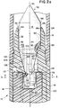
- Figs. 2a and 2b are, respectively, fragmentary front and rear portions of a section taken along line 2-2 of Fig. 1, with the cap, nib, transorb, and end plug of the instrument in place.
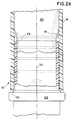
- Fig. 3 is a section taken along line 3-3 of Fig. 2, with the transorb and nib removed for greater clarity of illustration.
- a fluid dispensing instrument generally indicated at 10 comprises a nib holder 12, a nib 14, a generally tubular handle 16, a reservoir 18 refined by the inner wall of the handle 16, a transorb or absorbent body 20, a plug 22, and a cap 24.
- the nib holder 12, handle 16, and reservoir 18 are all a single molded part, while the nib 14, transorb 20, plug 22, and cap 24 are separate parts.
- the nib holder 12 comprises a front end defined by an opening 26, a back end 28, and a generally cylindrical inner wall 32 disposed between the front and back ends 26 and 28.
- the inner wall 32 shown here has a substantially round cross-section, but the shape of the cross-section is not critical herein.
- the prior art illustrates nibs having square, rectangular, triangular or other cross-sections, and nib holders having correspondingly sectioned interior walls.
- a longitudinal axis 34 is defined by the common center lines of the nib holder 12, nib 14, handle 16, and associated parts of the illustrated embodiment.
- the parts of the illustrated embodiment which cooperate with the inner wall 32 to secure the nib 14 are the barbs 36, 38, and 40 and the stops 42, 44, and 46.
- the number of barbs and stops is not critical; as few as one or as many as desired of each can be provided within the scope of the present invention.
- the barbs and stops 36-46 as illustrated are secured to and extend from the inner wall 32, it is not necessary that these be located there. It is only necessary that they be located in fixed relation to the inner wall 32.
- the nib 14 and transorb 20 are integral or capable of moving together axially, the barbs 36-40 and the stops 42-46, or any of them, can be located in the reservoir 18.
- the barbs 36-40 and the stops 42-46 alternate circumferentially about the axis 34. While the cooperating barbs and stops could be located one behind the other or in other relationships, this alternating circumferential relationship facilitates the molding of the barbs and stops as integral parts of the nib holder 12 in a single molding operation, without the need for subsequent forming, cutting, or other material moving steps. The need for "lost wax" or other precision molding methods is also avoided.
- Each barb such as 40, has a nib engaging end such as 48 which extends inward from the inner wall 32 toward the axis 34.
- the barb 40 also has a front end 50 merging with an axial rib 52, front facets 54 and 56, a rear facet 58, and an edge 60 dividing the facets 54 and 56.
- the root of the barb 40 is integral with the inner wall 32.
- each rear facet 58 is inclined toward the rear of the instrument 10 from its root 62 to the nib engaging end 48, increasing the sharpness of the nib-engaging end 48 and its tendency to penetrate the nib 14.
- Each axial rib, such as 52 has a triangular section with its base at the inner wall 32 and its apex extending radially inwardly toward the axis 34.
- each barb such as 40 can be regarded as an axial extension of an axial rib such as 52.
- the ribs such as 52 engage the nib 14 to center it within the inner wall 32.
- the rib 52 is further defined by its front end 64 and its back end 66, which are axially separated. With the barb 40 and rib 52 so aligned, the apex of the rib 52 merges with the edge 60 of the barb 40 and with the nib engaging end 48.
- the stop 42 projects toward the axis 34 from the inner wall 32.
- the stop 42 has a front surface 70, an inner surface 72, sides 74 and 76 (with reference here to Fig. 1), and a rear surface 78.
- the front surface 70 is approximately square in cross-section, so it will resiliently deform the nib 14 instead of cutting into its surface.
- the stop 42 as illustrated projects inwardly from the inner wall 32, in another embodiment the stop 42 could project perpendicularly away from the axis 34, or could be located further back in the instrument 10.
- the front surface 79 of the plug 22 can serve as such a stop within the scope of the present invention.
- the stop 42 also lies behind an axial rib 82 having a front end 84, a back end 86, and a sharp, axially extending edge lying between the ends 84 and 86.
- This rib has substantially the same dimensions as the rib 52. However, its back end 86 ends abruptly at the surface 70, instead of merging with the inner surface 72 of the stop 42.
- a total of six axial ribs are provided, at intervals of 60 degrees, to center and axially guide the nib 14.
- the surface 70 of the stop 42 lies substantially forward of the nib-engaging end 48 of the barb 40. This relationship is not essential to the present invention.
- the stops and barbs could be exchanged and still function.
- the nib 14 is similar to the nib described in previously-cited U.S. Patent No. 4,229,115. Like the nib shown in the '115 patent, the present nib 14 has a fluid-dispensing tip 90 defining its front end and a body generally indicated at 92 which is defined as the entire nib from behind its fluid dispensing tip 90 to its back end 94. The location of the division between the tip 90 and the body 92 is not significant, and does not necessarily lie at a point of discontinuity such as the edge 96.
- the nib 14 further comprises a barrel 98 which is defined here, for convenience only, as the portion of the nib 14 between the front edge 96 and a back edge 100. The surface of the barrel 98 between the edges 96 and 100 is substantially cylindrical. Behind the barrel 98, in this embodiment, is a conical abutment 102 lying between the edge 100 and the edge 104 as illustrated in Fig. 2.
- the nib 14 is nominally entirely symmetrical about the axis 34.
- the abutment 102 is forced against the front surface 70 so the front surface 70 of the stop such as 42 resiliently deforms (here, compresses) the abutment 102 axially forward from its relaxed position. (Its relaxed position is shown in phantom lines in relation to the stop 70.)
- the portions of the abutment 102 axially in line with the ends such as 48 of the barbs are substantially undeformed, as illustrated in Fig. 2.
- the cylindrical surface of the barrel 98 is received by the inner wall 32, and the ribs such as 52 and 82 indent the cylindrical surface.
- the region behind the back edge 104 of the abutment 102 is a trunk 106 which is generally cylindrical, except that its rear end is pinched at the groove 108.
- the groove 108 is an artifact of the molding process.
- the trunk 106 has a smaller diameter than the barrel 98.
- the abutment 102 defines a shoulder between the barrel 98 and the trunk 106.
- the trunk 106 has two functions. First, its cylindrical surface is impaled by the nib-engaging end 48 of the barb 40, as illustrated in Fig. 2. Second, the trunk 106, as well as the barrel 98, wicks fluid from the transorb 20 to the tip 90.
- the transorb 20 is an absorbent body which is inserted into the reservoir 18 through the back end 110 before the plug 22 is inserted.
- the front end 112 of the transorb 20 butts against the stop formed by the back end 28 of the nib holder 12 in this embodiment.
- the back end 94 of the nib 14 is received within a cylindrical recess 114 in the front end 112 of the transorb 20 in good fluid transfer relationship.
- the nib 14 and transorb 20 could be and sometimes are provided as a single member, but it is better to provide two coupled members, as illustrated, because the nib 14 must be much harder in order to withstand the pressure of writing or other fluid dispensing operations in which the instrument 10 is drawn across a surface.
- the transorb stop defined in part by the back ends such as 28 of the stops such as 42 is not circumferentially continuous. It is further defined by the three abutments shown in Fig. 1 as 116, 118, and 120. There are circumferential gaps between each stop such as 42 and the flanking abutments such as 116 and 118. These gaps, as well as the groove (15) shown in the nib of U.S. Patent No. 4,229,115, which is omitted here for clarity of illustration, convey ambient air between the nib 14 and the inner wall 32.
- the transorb 20 is spaced from and centered within the reservoir wall 18 throughout at least the forward part of its length by ribs 122, 124, and 126 to convey air between the transorb 20 and the wall 18 to the back of the instrument 10. It is necessary to introduce air in this manner to replace the fluid lost during dispensing. Otherwise, a partial vacuum would develop within the writing instrument 10 as fluid was dispensed, stopping the flow of fluid to the fluid dispensing tip 90 of the nib 14.
- the portion of the nib 14 forward of the edge 96 protrudes beyond the front end 26 of the instrument 10, giving the nib holder 12 the appearance of an ordinary pen or pencil which has a conical writing tip. While this construction is aesthetically pleasing, the edge 96 could be shifted forward or back with respect to the front end 26 of the nib holder 12 without departing from the present invention.
- the nib 14 can be made of any porous, resilient material.
- the material of the nib 14 is resilient because it will deform when compressed or stretched and will return to its original dimensions when the compressing or stretching force is released and the nib is allowed to relax.
- Three examples of nibs which are both resilient and porous enough to serve the present purposes are ordinary felt nibs, sintered particle nibs, and bonded fiber nibs.
- Sintered particle nibs can be made from crystals of ultra high molecular weight polyethylene which are oriented, consolidated, and bonded by extrusion to form a solid body having a network of interstitial spaces between the crystals.
- the degree of bonding is sufficient to provide resilience and hardness, without obstructing the interstitial spaces.
- the interstitial spaces wick ink longitudinally through the nib.
- Bonded fiber webs are made by bonding and extruding a tow of parallel fibers made of ultra high molecular weight polyethylene to form a rod of longitudinally oriented fibers.
- the rod can be machined to form a resilient nib having the preferred construction. Interstitial spaces between the fibers wick ink longitudinally through the nib.
- the nib 14 Due to the resilience of the body of the nib 14, particularly the portion of the nib 14 which is forward of the abutment 102, the nib 14 itself functions as spring means operatively engaging the stops 42 of the nib holder 12 for urging the body 92 of the nib 14 forward into engagement with the nib engaging end 48 of each barb such as 40.
- the nib 14 is positioned so its barrel 98 is received by the inner wall 32 of the nib holder 12 forward of the stops 42, 44, and 46.
- the trunk 106 is received by the inner surfaces such as 72 of the stops such as 42.
- the inner surfaces such as 72 define a passage of reduced diameter which guides the trunk 106 and locates it in the center of the fluid dispensing instrument 10, so the center line of the nib 14 coincides with the axis 34.
- the preferred method of permanently securing the nib 14 in the nib holder 12 of the fluid dispensing instrument 10 comprises the steps of providing the nib holder and nib previously described, aligning them on the axis 34 with the nib 14 in front of the nib holder 12, and inserting the body of the nib 14 into the space enclosed by the inner wall 32 of the nib holder 12, via the axial opening defined in the front end 26 of the nib holder 12.
- the nib is inserted sufficiently that at least a portion of the body 92 is lodged in the inner wall 32; the barbs 36, 38, and 40 engage the body 92 of the nib 14; and the abutment 102 of the nib 14 abuts the stops 42, 44, and 46 of the nib holder 12.
- this first step is accomplished by inserting the nib 14 sufficiently that the abutment 102 just touches the surfaces such as 70 of the stops such as 42.
- an axial force is exerted on the nib 14 in the vicinity of the fluid dispensing tip 90, as with a ram having a surface complementary to that of the conical surface between the fluid dispensing tip 90 and the front edge 96.
- This axial force urges the nib 14 further into the opening defining the front end 26, compressing the abutment 102 of the nib 14 forward of the abutment 102 and urging the nib 14 axially back against the stops such as 42.
- This axial force also urges the trunk 106 of the nib 14 further back in the nib holder 12.
- the axial force applied in the previous step is removed, thereby allowing the resiliently compressed portion of the nib 14 forward of the abutment 102 to expand axially, thereby urging at least a part of the body of the nib 14, and here in particular the trunk 106, axially forward.
- the barbs such as 48 cut into and penetrate beneath the surface of the trunk 106. This is illustrated in Fig. 2.
- the portion of the nib 14 in front of the abutment 102 which has been compressed by the axial force, will not be fully relaxed when the nib engaging ends 48 of the barbs have sufficiently engaged the cylindrical surface 106 and underlying portions of the trunk 106 to stop the trunk 106 from moving forward.
- the barrel 98 will be urged axially forward by the resilience of the compressed material ahead of the abutment 102, while the part of the body 92 between the stops such as 42 and the nib engaging ends such as 48 of the barbs will be in tension, and thus resiliently stretched, urging the nib 14 back.
- Both the compressed and the stretched parts of the body 92 function as spring means.
- the resilient expansion of the trunk 106 will substantially entirely counteract the resilient compression of the nib 14 against the stops such as 42.
- the nib 14 will remain securely impaled on the barbs such as 40, thus preventing the nib 14 from being removed from the nib holder 12 except by breaking the nib 14 or the nib holder 12.
- the positions of the barbs such as 40 and stops such as 42 can be exchanged, within the scope of the invention.
- the portion of the body 92 between the barbs and stops will be resiliently compressed after the axial force is removed, while the portions of the body 92 forward of the barbs and behind the stops will be unstressed.
- the barbs and stops can also be reversed (i.e. rotated 180 degrees about an axis intersecting and perpendicular to the axis 34) and the nib 14 can be inserted through an opening at the back of the nib holder 12 without departing from the present invention.
- the nib 14 will protrude through a second opening at the front of the nib holder 12, as in the illustrated embodiment.
- this fluid dispensing instrument will have a permanently inserted nib, held by interior components molded into the nib holder 12. Thus, there is no need for a separate staking step or for the insertion of a pin or other part to retain the nib in the nib holder. Furthermore, a fluid dispensing instrument has been described which has a body 10 molded as a single part, and which requires no additional operation such as punching, cutting, or the like to enable it to permanently engage a separately formed nib.
Abstract
Fluid dispensing instrument (10), such as a writing instrument, comprising a nib holder (12) and a nib (14). The nib holder comprises a generally cylindrical inner wall (32) disposed between its front (26) and back (28) ends, having an opening at one end to receive a nib. Stops (42,44,46) limit the depth of axial insertion of a nib through the opening. Barbs (36,38,40) prevent axial withdrawal of a nib from the opening. The nib comprises a fluid dispensing tip (90) defining its front end and a body (92) made at least in part of resilient material defining its back end. When the writing instrument is assembled, the body is engaged by and resiliently deformed between the barb means and stop means. Also, a method of permanently securing a nib in the nib holder of a fluid dispensing instrument, comprising the steps of inserting the nib in the nib holder through the opening until an abutment of the nib engages a stop of the nib holder, applying an insertion force sufficient to compress the resilient part of the nib and thus move at least part of the nib axially in the nib holder, and removing the insertion force. When the insertion force is removed, the compressed part of the nib relaxes and the part of the nib which previously moved axially in one direction moves axially the other way. When this happens the barb of the nib holder engages and digs into the moving part of the body. Some residual tension will remain in the body after the insertion force is removed if the barbs engage sufficiently to prevent further axial movement of the nib body before the compressed resilient portion of the nib is fully relaxed.
Description
- The present invention relates generally to an instrument for dispensing a line of fluid from a reservoir onto a surface when the instrument is drawn across the surface. The invention relates particularly to a writing and drawing instrument of the type having a nib, and more particularly to such an instrument in which the nib functions as a wick to transport ink from a reservoir to its writing tip.
- In a conventional fluid-dispensing instrument having a wicking nib, the nib is inserted in a nib holder so its back end is in fluid communication with a fluid reservoir and its front end extends out of the nib holder and serves as a writing tip. The reservoir typically is a rigid extension of the nib holder which serves as a handle. The reservoir typically contains a transorb -- an absorbent body in which the fluid is absorbed. One such device is the familiar felt-tipped pen or marker.
- In one common marker design, the nib holder and reservoir are made as one molded piece. The front end of the piece functions as the nib holder and has an opening through which the nib is inserted. The back end of the piece has a larger opening to receive the transorb and ink. The larger opening is permanently plugged after the transorb is inserted. One difficulty with this design is how to secure the nib in the nib holder so it is easy to insert when the pen is manufactured, yet difficult to either remove from the nib holder or push into the reservoir when the marker is in the hands of consumers (especially children).
- U.S. Patent No. 3,089,182, issued to Lofgren on May 14, 1963, discloses a marking device in which the
marking element 16, which may be felt or the like, is held within thetubular neck 22 by stakes such as 28 and 30 which are formed in the metal wall of the container by tools after the marking element is inserted, as illustrated in Fig. 8 and described in Col. 2, lines 53-60. The reference indicates that the illustrated simple, one piece container lowers manufacturing cost (Col. 1, lines 28-30). - U.S. Patent No. 3,684,389 was issued to Eron et al. on August 15, 1972. The writing nibs described in the reference are removable so they can be interchanged with other nibs. (See: the abstract and Col. 1, lines 53-58). Referring to Figs. 1 and 11 in particular, the reference shows
protrusions 28 which are intended to engage a nib such as 24. Fig. 3 shows that theprotrusions 28 are inclined inwardly toward the opening through which the nib is inserted. - U.S. Patent No. 3,003,181, issued to Rosenthal on October 10, 1951, teaches a marking device having a
felt nib 16 retained in achannel 24 of anib holder 20, which in turn is retained by areservoir 10. Thenib 16 extends axially beyond both ends of thenib holder 20. Col. 2, lines 55-62, indicates that theshoulders 48 of the inner portion of the nib are radially compressed when the nib is inserted in theholder 20 through thechannel 24. Theshoulders 48 spring out to lock the nib in place by engaging the annular face 30 of the nib holder. At the same time, thewings 38 at the other end of the nib engage thestop 40 to secure the nib in place. - The Olinsky U.S. Patent No. 4,229,115, issued October 21, 1980, is owned by the assignee of the present invention. This reference illustrates a nib for a writing or drawing instrument which is similar to the nib described herein.
- U.S. Patent No. 4,500,222 was issued to Clading-Boel on February 19, 1985. This reference shows a writing instrument including a core or transorb which abuts against a writing ball. Figs. 1 and 2 show triangular-section centering ribs 17. Col. 2, lines 55-64 of the reference indicate that these ribs cut into the core and radially locate and axially retain the core. The core is inserted at the back end of the pen, remote from the ball, as stated at Col. 1,
lines 33 and 34. - U.S. Patent No. 4,568,214 was issued to Abbe et al. on February 4, 1986. A nib 1 has a flange 101 which is captured by a shoulder of the outer barrel and an abutment plate of an inner barrel of the device to hold the nib in place. The nib 1 is made of a porous synthetic resin, as disclosed in Col. 2, lines 13-15 of the specification. It appears that the nib 1 and associated parts are inserted in the barrel before the plug 9 is in place, through the rear end of the barrel.
- U.S. Patent No. 4,583,875, issued to Manusch et al. on April 22, 1986, describes a writing or drawing instrument having a
nib holder 20, one end of which is formed into a closed membrane 6 which has astop 18 integrally formed. The membrane 6 is pierced by axial insertion of a tool shaped like the trunk of the nib. Thestop 18 prevents further insertion of the nib. The reference discloses that, after the membrane 6 is pierced, the residual portion of the membrane engages the nib to keep it in place (Figs. 1 and 4, Col. 2, lines 33-41, Col. 5, lines 12-19, Col. 2, lines 61-Col. 3, line 5). Returning to Fig. 1, theribs 3 are triangular in section (Col. 3, lines 42-52). The reference indicates that, apart from the nib, the pen can be molded in one piece with two cores (Col. 5, lines 3-11). The reference claims at Col. 6, lines 14-19, that a sintered powder nib can be used, and that no retaining pin or adhesive is necessary to hold the nib in place. - The Smit patent, U.S. Patent No. 4,602,886, issued to July 29, 1986 describes apparatus for advancing a wax crayon out of its case.
- One object of the present invention is a fluid dispensing instrument having a nib and a nib holder which are substantially irreversibly joined in fixed relation without the need for a separate pin or other fastener to join them.
- An additional object of the invention is a method for substantially irreversibly joining the nib and nib holder of a fluid dispensing instrument simply by thrusting the former into the latter, without additional forming steps such as staking, puncturing, machining, and the like.
- Another object of the present invention is a fluid dispensing instrument which has a nib holder, handle, and reservoir formed as a single, as-molded part; a nib also formed as a single, as-molded part; and means molded into the two parts for substantially permanently joining them.
- Yet another object of the invention is a fluid dispensing instrument having a nib made at least partially of resilient material which functions like a built-in spring engaged between the nib and nib holder.
- Other objects of the invention and ways of achieving them will become apparent from the present drawings and description.
- One aspect of the present invention is a fluid dispensing instrument comprising a nib holder and a nib. The nib holder comprises a front end, a back end, and a generally cylindrical inner wall disposed between its front and back ends. An insertion opening is provided at one end of the nib holder to receive a nib. (The nib protrudes from an opening at the front of the nib holder in the completed instrument.) The nib holder has stop means located in fixed relation to the inner wall and adapted to limit the depth of axial insertion of a nib through the opening. Barb means located in fixed relation to the inner wall is adapted to permit axial insertion but prevent axial withdrawal of a nib through the insertion opening. The gradual slope angles of the barbs in the preferred embodiment guide the nib into the barrel, preventing misalignment with the reservoir chamber.
- The nib comprises a fluid dispensing tip defining its front end, a body made at least partially of resilient material defining its back end, and an abutment to engage the stop means of the nib holder. When the writing instrument is assembled, the body of the nib is engaged and resiliently deformed by the barb means and stop means.
- Another aspect of the invention is a method of permanently securing a nib in the nib holder of a fluid dispensing instrument, comprising the steps of providing a nib and a nib holder, each as described above, and inserting the nib in the nib holder through the insertion opening in the nib holder.
- The inserting step is started by inserting the nib into the opening of the nib holder until the abutment of the nib engages the stop of the nib holder. The inserting step is completed by applying an insertion force sufficient to compress the resilient part of the nib and thus move at least part of the body of the nib further axially in the nib holder. When this insertion force is removed, the compressed part of the nib relaxes, the part of the nib which previously moved further axially reverses direction, and the barbs of the nib holder engage and dig into the moving part of the nib body. Some residual tension or compression will remain in the body of the nib after the insertion force is removed if the barb engages sufficiently to prevent further movement of the nib body before the compressed resilient portion of the nib is fully relaxed.
- Several advantages of the invention are as follows. The nib holder, handle, and reservoir of the fluid-dispensing instrument can be made as a single molding which does not require machining or forming operations before it can receive the nib. The dispensing instrument is thus assembled easily from a small number of easily formed components. No forming step or fastener is needed to join the nib and nib holder, yet the nib is permanently lodged in the nib holder.
- Fig. 1 is front elevation of one embodiment of a fluid dispensing instrument according to the present invention, with the nib and cap removed for clarity of illustration.
- Figs. 2a and 2b are, respectively, fragmentary front and rear portions of a section taken along line 2-2 of Fig. 1, with the cap, nib, transorb, and end plug of the instrument in place.
- Fig. 3 is a section taken along line 3-3 of Fig. 2, with the transorb and nib removed for greater clarity of illustration.
- While the invention will be described in connection with one or more preferred embodiments, it will be understood that the invention is not limited to those embodiments. On the contrary, the invention includes all alternatives, modifications, and equivalents as may be included within the spirit and scope of the appended claims.
- Referring to the Figures, in this embodiment a fluid dispensing instrument generally indicated at 10 comprises a
nib holder 12, anib 14, a generallytubular handle 16, areservoir 18 refined by the inner wall of thehandle 16, a transorb orabsorbent body 20, aplug 22, and acap 24. In this embodiment, thenib holder 12, handle 16, andreservoir 18 are all a single molded part, while thenib 14,transorb 20, plug 22, and cap 24 are separate parts. - The
nib holder 12 comprises a front end defined by anopening 26, aback end 28, and a generally cylindricalinner wall 32 disposed between the front and back ends 26 and 28. Theinner wall 32 shown here has a substantially round cross-section, but the shape of the cross-section is not critical herein. The prior art illustrates nibs having square, rectangular, triangular or other cross-sections, and nib holders having correspondingly sectioned interior walls. Alongitudinal axis 34 is defined by the common center lines of thenib holder 12,nib 14, handle 16, and associated parts of the illustrated embodiment. - Referring now in particular to Figs. 1 and 2a, the parts of the illustrated embodiment which cooperate with the
inner wall 32 to secure thenib 14 are thebarbs stops inner wall 32, it is not necessary that these be located there. It is only necessary that they be located in fixed relation to theinner wall 32. For example, if thenib 14 andtransorb 20 are integral or capable of moving together axially, the barbs 36-40 and the stops 42-46, or any of them, can be located in thereservoir 18. - In this embodiment, the barbs 36-40 and the stops 42-46 alternate circumferentially about the
axis 34. While the cooperating barbs and stops could be located one behind the other or in other relationships, this alternating circumferential relationship facilitates the molding of the barbs and stops as integral parts of thenib holder 12 in a single molding operation, without the need for subsequent forming, cutting, or other material moving steps. The need for "lost wax" or other precision molding methods is also avoided. - Each barb, such as 40, has a nib engaging end such as 48 which extends inward from the
inner wall 32 toward theaxis 34. In this embodiment, thebarb 40 also has afront end 50 merging with anaxial rib 52,front facets rear facet 58, and anedge 60 dividing thefacets barb 40 is integral with theinner wall 32. In this embodiment, eachrear facet 58 is inclined toward the rear of theinstrument 10 from itsroot 62 to thenib engaging end 48, increasing the sharpness of the nib-engagingend 48 and its tendency to penetrate thenib 14. - Each axial rib, such as 52, has a triangular section with its base at the
inner wall 32 and its apex extending radially inwardly toward theaxis 34. Thus, each barb such as 40 can be regarded as an axial extension of an axial rib such as 52. The ribs such as 52 engage thenib 14 to center it within theinner wall 32. Therib 52 is further defined by itsfront end 64 and itsback end 66, which are axially separated. With thebarb 40 andrib 52 so aligned, the apex of therib 52 merges with theedge 60 of thebarb 40 and with thenib engaging end 48. - Each of the
stops stop 42 will be described in detail here. Thestop 42 projects toward theaxis 34 from theinner wall 32. Thestop 42 has afront surface 70, aninner surface 72, sides 74 and 76 (with reference here to Fig. 1), and arear surface 78. Thefront surface 70 is approximately square in cross-section, so it will resiliently deform thenib 14 instead of cutting into its surface. While thestop 42 as illustrated projects inwardly from theinner wall 32, in another embodiment thestop 42 could project perpendicularly away from theaxis 34, or could be located further back in theinstrument 10. As an extreme example, if the transorb 20 andnib 14 move axially as a unit or are one part, thefront surface 79 of theplug 22 can serve as such a stop within the scope of the present invention. - The
stop 42 also lies behind anaxial rib 82 having afront end 84, aback end 86, and a sharp, axially extending edge lying between theends rib 52. However, itsback end 86 ends abruptly at thesurface 70, instead of merging with theinner surface 72 of thestop 42. Thus, in this embodiment a total of six axial ribs are provided, at intervals of 60 degrees, to center and axially guide thenib 14. Thesurface 70 of thestop 42 lies substantially forward of the nib-engagingend 48 of thebarb 40. This relationship is not essential to the present invention. The stops and barbs could be exchanged and still function. - The
nib 14 is similar to the nib described in previously-cited U.S. Patent No. 4,229,115. Like the nib shown in the '115 patent, thepresent nib 14 has a fluid-dispensingtip 90 defining its front end and a body generally indicated at 92 which is defined as the entire nib from behind itsfluid dispensing tip 90 to its back end 94. The location of the division between thetip 90 and thebody 92 is not significant, and does not necessarily lie at a point of discontinuity such as theedge 96. Thenib 14 further comprises abarrel 98 which is defined here, for convenience only, as the portion of thenib 14 between thefront edge 96 and aback edge 100. The surface of thebarrel 98 between theedges barrel 98, in this embodiment, is aconical abutment 102 lying between theedge 100 and the edge 104 as illustrated in Fig. 2. - In this embodiment, the
nib 14 is nominally entirely symmetrical about theaxis 34. However, when thenib 14 is inserted in thenib holder 12, as shown in Figure 2, theabutment 102 is forced against thefront surface 70 so thefront surface 70 of the stop such as 42 resiliently deforms (here, compresses) theabutment 102 axially forward from its relaxed position. (Its relaxed position is shown in phantom lines in relation to thestop 70.) At the same time, the portions of theabutment 102 axially in line with the ends such as 48 of the barbs are substantially undeformed, as illustrated in Fig. 2. The cylindrical surface of thebarrel 98 is received by theinner wall 32, and the ribs such as 52 and 82 indent the cylindrical surface. - Looking further back on the
body 92 of thenib 14, the region behind the back edge 104 of theabutment 102 is atrunk 106 which is generally cylindrical, except that its rear end is pinched at thegroove 108. Thegroove 108 is an artifact of the molding process. In this embodiment, thetrunk 106 has a smaller diameter than thebarrel 98. Theabutment 102 defines a shoulder between thebarrel 98 and thetrunk 106. Thetrunk 106 has two functions. First, its cylindrical surface is impaled by the nib-engagingend 48 of thebarb 40, as illustrated in Fig. 2. Second, thetrunk 106, as well as thebarrel 98, wicks fluid from thetransorb 20 to thetip 90. - The
transorb 20 is an absorbent body which is inserted into thereservoir 18 through theback end 110 before theplug 22 is inserted. Thefront end 112 of thetransorb 20 butts against the stop formed by theback end 28 of thenib holder 12 in this embodiment. The back end 94 of thenib 14 is received within a cylindrical recess 114 in thefront end 112 of thetransorb 20 in good fluid transfer relationship. Thenib 14 andtransorb 20 could be and sometimes are provided as a single member, but it is better to provide two coupled members, as illustrated, because thenib 14 must be much harder in order to withstand the pressure of writing or other fluid dispensing operations in which theinstrument 10 is drawn across a surface. - In this embodiment, the transorb stop defined in part by the back ends such as 28 of the stops such as 42 is not circumferentially continuous. It is further defined by the three abutments shown in Fig. 1 as 116, 118, and 120. There are circumferential gaps between each stop such as 42 and the flanking abutments such as 116 and 118. These gaps, as well as the groove (15) shown in the nib of U.S. Patent No. 4,229,115, which is omitted here for clarity of illustration, convey ambient air between the
nib 14 and theinner wall 32. As is conventional, thetransorb 20 is spaced from and centered within thereservoir wall 18 throughout at least the forward part of its length byribs wall 18 to the back of theinstrument 10. It is necessary to introduce air in this manner to replace the fluid lost during dispensing. Otherwise, a partial vacuum would develop within the writinginstrument 10 as fluid was dispensed, stopping the flow of fluid to thefluid dispensing tip 90 of thenib 14. - In the illustrated embodiment, the portion of the
nib 14 forward of theedge 96 protrudes beyond thefront end 26 of theinstrument 10, giving thenib holder 12 the appearance of an ordinary pen or pencil which has a conical writing tip. While this construction is aesthetically pleasing, theedge 96 could be shifted forward or back with respect to thefront end 26 of thenib holder 12 without departing from the present invention. - The
nib 14 can be made of any porous, resilient material. The material of thenib 14 is resilient because it will deform when compressed or stretched and will return to its original dimensions when the compressing or stretching force is released and the nib is allowed to relax. Three examples of nibs which are both resilient and porous enough to serve the present purposes are ordinary felt nibs, sintered particle nibs, and bonded fiber nibs. - Sintered particle nibs can be made from crystals of ultra high molecular weight polyethylene which are oriented, consolidated, and bonded by extrusion to form a solid body having a network of interstitial spaces between the crystals. The degree of bonding is sufficient to provide resilience and hardness, without obstructing the interstitial spaces. The interstitial spaces wick ink longitudinally through the nib.
- Bonded fiber webs are made by bonding and extruding a tow of parallel fibers made of ultra high molecular weight polyethylene to form a rod of longitudinally oriented fibers. The rod can be machined to form a resilient nib having the preferred construction. Interstitial spaces between the fibers wick ink longitudinally through the nib.
- Due to the resilience of the body of the
nib 14, particularly the portion of thenib 14 which is forward of theabutment 102, thenib 14 itself functions as spring means operatively engaging thestops 42 of thenib holder 12 for urging thebody 92 of thenib 14 forward into engagement with thenib engaging end 48 of each barb such as 40. - In this embodiment, the
nib 14 is positioned so itsbarrel 98 is received by theinner wall 32 of thenib holder 12 forward of thestops trunk 106, on the other hand, is received by the inner surfaces such as 72 of the stops such as 42. The inner surfaces such as 72 define a passage of reduced diameter which guides thetrunk 106 and locates it in the center of thefluid dispensing instrument 10, so the center line of thenib 14 coincides with theaxis 34. - The preferred method of permanently securing the
nib 14 in thenib holder 12 of thefluid dispensing instrument 10 comprises the steps of providing the nib holder and nib previously described, aligning them on theaxis 34 with thenib 14 in front of thenib holder 12, and inserting the body of thenib 14 into the space enclosed by theinner wall 32 of thenib holder 12, via the axial opening defined in thefront end 26 of thenib holder 12. The nib is inserted sufficiently that at least a portion of thebody 92 is lodged in theinner wall 32; thebarbs body 92 of thenib 14; and theabutment 102 of thenib 14 abuts thestops nib holder 12. In this embodiment, this first step is accomplished by inserting thenib 14 sufficiently that theabutment 102 just touches the surfaces such as 70 of the stops such as 42. - In the next step of the method, an axial force is exerted on the
nib 14 in the vicinity of thefluid dispensing tip 90, as with a ram having a surface complementary to that of the conical surface between thefluid dispensing tip 90 and thefront edge 96. This axial force urges thenib 14 further into the opening defining thefront end 26, compressing theabutment 102 of thenib 14 forward of theabutment 102 and urging thenib 14 axially back against the stops such as 42. This axial force also urges thetrunk 106 of thenib 14 further back in thenib holder 12. - In the next step in assembling the
instrument 10, the axial force applied in the previous step is removed, thereby allowing the resiliently compressed portion of thenib 14 forward of theabutment 102 to expand axially, thereby urging at least a part of the body of thenib 14, and here in particular thetrunk 106, axially forward. As a result, the barbs such as 48 cut into and penetrate beneath the surface of thetrunk 106. This is illustrated in Fig. 2. - In the preferred mode of practicing the invention, the portion of the
nib 14 in front of theabutment 102, which has been compressed by the axial force, will not be fully relaxed when the nib engaging ends 48 of the barbs have sufficiently engaged thecylindrical surface 106 and underlying portions of thetrunk 106 to stop thetrunk 106 from moving forward. As a result, when the axial force between thenib 14 andnib holder 12 is no longer being applied, thebarrel 98 will be urged axially forward by the resilience of the compressed material ahead of theabutment 102, while the part of thebody 92 between the stops such as 42 and the nib engaging ends such as 48 of the barbs will be in tension, and thus resiliently stretched, urging thenib 14 back. - Both the compressed and the stretched parts of the
body 92 function as spring means. The resilient expansion of thetrunk 106 will substantially entirely counteract the resilient compression of thenib 14 against the stops such as 42. As a result of this dynamic balance, thenib 14 will remain securely impaled on the barbs such as 40, thus preventing thenib 14 from being removed from thenib holder 12 except by breaking thenib 14 or thenib holder 12. - The positions of the barbs such as 40 and stops such as 42 can be exchanged, within the scope of the invention. In such an embodiment, the portion of the
body 92 between the barbs and stops will be resiliently compressed after the axial force is removed, while the portions of thebody 92 forward of the barbs and behind the stops will be unstressed. - The barbs and stops can also be reversed (i.e. rotated 180 degrees about an axis intersecting and perpendicular to the axis 34) and the
nib 14 can be inserted through an opening at the back of thenib holder 12 without departing from the present invention. In the assembledinstrument 10, thenib 14 will protrude through a second opening at the front of thenib holder 12, as in the illustrated embodiment. - It is contemplated that this fluid dispensing instrument will have a permanently inserted nib, held by interior components molded into the
nib holder 12. Thus, there is no need for a separate staking step or for the insertion of a pin or other part to retain the nib in the nib holder. Furthermore, a fluid dispensing instrument has been described which has abody 10 molded as a single part, and which requires no additional operation such as punching, cutting, or the like to enable it to permanently engage a separately formed nib.
Claims (28)
- A fluid dispensing instrument comprising:a. a nib holder comprising a front end; a back end; a generally cylindrical inner wall disposed between said front and back ends and defining an axis; an opening in one said end; stop means located in fixed relation to said inner wall and adapted to limit the depth of axial insertion of a nib; and barb means located in fixed relation to said inner wall and adapted to prevent axial withdrawal of a nib; andb. a nib comprising a fluid dispensing tip defining its front end and a body made at least partially of resilient material defining its back end, said body being engaged and resiliently deformed by said barb means and said stop means to secure said nib in place.
- The fluid dispensing instrument of claim 1, wherein said stop means comprises at least a first stop, and wherein said barb means comprises at least a first barb having a forward end and a nib-engaging end, the latter extending backward in relation to the front end of said nib holder.
- The fluid dispensing instrument of claim 2, wherein said nib holder is a single molded plastic part.
- The fluid dispensing instrument of claim 2, wherein said first barb is secured to said inner wall.
- The fluid dispensing instrument of claim 2, wherein said nib holder further comprises second and third barbs, each fixed in relation to said inner wall and each having a forward end and a nib-engaging end, the latter extending backward in relation to the front end of said nib holder, said first, second and third barbs being circumferentially spaced in relation to said inner wall.
- The fluid dispensing instrument of claim 2, wherein said nib holder further comprises at least a first axial rib fixed to said inner wall and projecting from said inner wall into engagement with the body of said nib, said first rib having front and back ends.
- The fluid dispensing instrument of claim 6, wherein said first barb is an axial extension of the back end of said first axial rib.
- The fluid dispensing instrument of claim 6, wherein said first axial rib has a sharp edge extending axially and projecting inward with respect to said inner wall for engaging the body of said nib.
- The fluid dispensing instrument of claim 8, wherein the edge of said first axial rib merges with the nib-engaging end of said first barb.
- The fluid dispensing instrument of claim 2, wherein said first stop is fixed to and projects inwardly from the inner wall of said nib holder.
- The fluid dispensing instrument of claim 2, further comprising second and third stops located in fixed relation to said inner wall, said first, second, and third stops being circumferentially spaced.
- The fluid dispensing instrument of claim 11, further comprising second and third barbs, each located in fixed relation to said inner wall and each having a nib-engaging end extending backward in relation to the front end of said nib holder, said first, second and third barbs being circumferentially spaced about the axis of said inner wall.
- The fluid dispensing instrument of claim 12, wherein said barbs and said stops alternate circumferentially about the axis of said inner wall.
- The fluid dispensing instrument of claim 2, wherein said first stop is located forward of the nib engaging end of said first barb.
- The fluid dispensing instrument of claim 2, wherein the body of said nib comprises a trunk defining its rear end and a barrel disposed between said trunk and said fluid dispensing tip.
- The fluid dispensing instrument of claim 15, wherein said barrel has a larger diameter than said trunk.
- The fluid dispensing instrument of claim 15, wherein said body includes at least a first abutment for receiving said first stop.
- The fluid dispensing instrument of claim 15, wherein said barrel is received within said inner wall forward of said first stop.
- The fluid dispensing instrument of claim 2, wherein a resilient portion of said nib is located at least partially substantially forward of said first abutment and is resiliently compressed axially, thereby urging said first abutment toward said first stop.
- The fluid dispensing instrument of claim 2, wherein said resilient portion of said nib is located at least partially substantially behind said first abutment and is resiliently expanded axially, thereby urging said first abutment toward said first stop.
- The fluid dispensing instrument of claim 2, further comprising a handle on which said nib holder is mounted.
- The fluid dispensing instrument of claim 21, wherein said handle is generally tubular and has a cylindrical inner wall enclosing a reservoir in fluid communication with the body of said nib.
- The fluid dispensing instrument of claim 22, wherein said handle and said nib holder are a single molded part.
- The fluid dispensing instrument of claim 22, further comprising a transorb disposed within said reservoir in fluid transfer contact with the body of said nib.
- A fluid-dispensing instrument comprising:a. a one-piece nib holder comprising a front end; a back end; a generally cylindrical inner wall between said front and back ends; an opening at said front end; a plurality of circumferentially spaced stops secured to said inner wall; a plurality of circumferentially-spaced axial ribs fixed to and extending inward with respect to said inner wall, each said rib having axially spaced front and back ends and a sharp edge extending axially and projecting inwardly from said inner wall for slidably engaging the body of a nib; and a plurality of circumferentially-spaced barbs secured to said inner wall axially behind and circumferentially alternating with said stops, each of said barbs having a nib-engaging end extending backward in relation to the front end of said nib holder; andb. a nib made of axially resilient material and comprising a fluid-dispensing tip defining its front end; a body defining its back end and comprising a trunk having at least a portion lodged within said inner wall behind said plurality of stops and a barrel between said fluid-dispensing tip and said trunk received in said inner wall forward of said plurality of stops and having a larger diameter than said trunk; an abutment defined by a shoulder where said barrel and said trunk adjoin for receiving the stops of said nib holder; said nib being axially expanded between said stops and said barbs for urging at least a portion of the body of said nib forward into engagement with the nib-engaging ends of said barbs.
- A method of securing a nib in the nib holder of a fluid dispensing instrument, comprising the steps of:a. providing a nib holder comprising a front end; a back end; a generally cylindrical inner wall disposed between said front and back ends and defining an axis; an insertion opening at one of said ends; stop means located in fixed relation to said inner wall and adapted to limit the depth of axial insertion of a nib; and barb means located in fixed relation to said inner wall and adapted to prevent axial withdrawal of a nib;b. providing a nib comprising a fluid dispensing tip defining its front end and a body made at least in part of resilient material defining its back end;c. inserting the body of said nib into the inner wall of said nib holder sufficiently that at least a portion of said body is lodged in said inner wall, said barb means engages said body, and said body abuts said stop means;d. resiliently axially compressing at least a part of said nib by applying an axial force which urges said nib axially against said stop means; ande. removing said axial force, thereby allowing the resiliently compressed portion of said nib to expand axially, thereby urging at least a part of the body of said nib axially into engagement with said barb means.
- The method of claim 27, further comprising the preceding step of forming said nib holder as a single molded part
- The method of claim 27, wherein said opening is in the front end of said nib holder, said stop means prevents insertion of said nib through said opening, and said barb means prevents withdrawal of said nib through said opening.
Applications Claiming Priority (2)
| Application Number | Priority Date | Filing Date | Title |
|---|---|---|---|
| US64343391A | 1991-01-22 | 1991-01-22 | |
| US643433 | 1991-01-22 |
Publications (1)
| Publication Number | Publication Date |
|---|---|
| EP0496304A1 true EP0496304A1 (en) | 1992-07-29 |
Family
ID=24580806
Family Applications (1)
| Application Number | Title | Priority Date | Filing Date |
|---|---|---|---|
| EP92100780A Withdrawn EP0496304A1 (en) | 1991-01-22 | 1992-01-18 | Fluid-dispensing instruments having barbed nib holders |
Country Status (3)
| Country | Link |
|---|---|
| EP (1) | EP0496304A1 (en) |
| AU (1) | AU1033892A (en) |
| CA (1) | CA2059772A1 (en) |
Citations (7)
| Publication number | Priority date | Publication date | Assignee | Title |
|---|---|---|---|---|
| GB1086310A (en) * | 1964-12-23 | 1967-10-11 | Dainihonbungu Kabushiki Kaisha | Improvements in or relating to writing instruments |
| GB1350320A (en) * | 1972-05-16 | 1974-04-18 | Noguchi C | Marking pens |
| DE2319942A1 (en) * | 1973-04-19 | 1974-10-31 | Faber Castell A W | FASTENING OF A WRITING ELEMENT |
| US4229115A (en) * | 1979-02-12 | 1980-10-21 | Binney & Smith, Inc. | Nib for a writing instrument |
| GB2067475A (en) * | 1980-01-14 | 1981-07-30 | Waite & Son Ltd | Ball point pen tip |
| US4500222A (en) * | 1978-07-11 | 1985-02-19 | Waite & Son Limited | Aqueous ink writing tip |
| US4583875A (en) * | 1983-01-29 | 1986-04-22 | Pelikan Aktiengesellschaft | Method of nib attachment |
-
1992
- 1992-01-18 EP EP92100780A patent/EP0496304A1/en not_active Withdrawn
- 1992-01-20 AU AU10338/92A patent/AU1033892A/en not_active Abandoned
- 1992-01-21 CA CA 2059772 patent/CA2059772A1/en not_active Abandoned
Patent Citations (7)
| Publication number | Priority date | Publication date | Assignee | Title |
|---|---|---|---|---|
| GB1086310A (en) * | 1964-12-23 | 1967-10-11 | Dainihonbungu Kabushiki Kaisha | Improvements in or relating to writing instruments |
| GB1350320A (en) * | 1972-05-16 | 1974-04-18 | Noguchi C | Marking pens |
| DE2319942A1 (en) * | 1973-04-19 | 1974-10-31 | Faber Castell A W | FASTENING OF A WRITING ELEMENT |
| US4500222A (en) * | 1978-07-11 | 1985-02-19 | Waite & Son Limited | Aqueous ink writing tip |
| US4229115A (en) * | 1979-02-12 | 1980-10-21 | Binney & Smith, Inc. | Nib for a writing instrument |
| GB2067475A (en) * | 1980-01-14 | 1981-07-30 | Waite & Son Ltd | Ball point pen tip |
| US4583875A (en) * | 1983-01-29 | 1986-04-22 | Pelikan Aktiengesellschaft | Method of nib attachment |
Also Published As
| Publication number | Publication date |
|---|---|
| AU1033892A (en) | 1992-07-30 |
| CA2059772A1 (en) | 1992-07-23 |
Similar Documents
| Publication | Publication Date | Title |
|---|---|---|
| US4341482A (en) | Housing assembly for fluid marking device | |
| EP0683062B1 (en) | Applicator | |
| US5263786A (en) | Rotary-cam ball-point pen | |
| GB2088289A (en) | Marking pen | |
| US6517272B1 (en) | Double-chuck mechanical pencil | |
| WO1996023666A1 (en) | Side-knock mechanical pencil | |
| EP0625378A2 (en) | Liquid applicator and method of making same | |
| EP0496304A1 (en) | Fluid-dispensing instruments having barbed nib holders | |
| US4583875A (en) | Method of nib attachment | |
| EP1201456B1 (en) | Ball point pen | |
| EP0524600B1 (en) | Container for extending a stick-shaped material | |
| CA1102739A (en) | Nib retaining assembly for a writing instrument | |
| US5286127A (en) | Writing instrument | |
| EP0407002B1 (en) | Device for advancing and retracting writing element in writing instrument | |
| US4687363A (en) | Mechanical pencil and method for assembling the same | |
| EP0709233A1 (en) | Slider for mechanical pencil | |
| CN112638659A (en) | Writing instrument with refill | |
| US20220062608A1 (en) | Implant syringe | |
| EP0393377A2 (en) | Propelling device for a bar shaped article | |
| KR200202796Y1 (en) | Cartridge of makeup pencil | |
| US20040013462A1 (en) | Universal refill mechanism and method | |
| EP0538503A1 (en) | A rotary-cam ball-point pen | |
| JPH1016468A (en) | Plastic pipe assembly for writing instrument and its manufacture | |
| JPH0245031Y2 (en) | ||
| JPH0333509Y2 (en) |
Legal Events
| Date | Code | Title | Description |
|---|---|---|---|
| PUAI | Public reference made under article 153(3) epc to a published international application that has entered the european phase |
Free format text: ORIGINAL CODE: 0009012 |
|
| AK | Designated contracting states |
Kind code of ref document: A1 Designated state(s): AT BE CH DE ES FR GB IT LI LU NL |
|
| 17P | Request for examination filed |
Effective date: 19921204 |
|
| STAA | Information on the status of an ep patent application or granted ep patent |
Free format text: STATUS: THE APPLICATION HAS BEEN WITHDRAWN |
|
| 18W | Application withdrawn |
Withdrawal date: 19931203 |