EP0496105A1 - Remotely actuated sanitary fitting - Google Patents
Remotely actuated sanitary fitting Download PDFInfo
- Publication number
- EP0496105A1 EP0496105A1 EP91122089A EP91122089A EP0496105A1 EP 0496105 A1 EP0496105 A1 EP 0496105A1 EP 91122089 A EP91122089 A EP 91122089A EP 91122089 A EP91122089 A EP 91122089A EP 0496105 A1 EP0496105 A1 EP 0496105A1
- Authority
- EP
- European Patent Office
- Prior art keywords
- handle
- sanitary fitting
- main housing
- fitting according
- housing
- Prior art date
- Legal status (The legal status is an assumption and is not a legal conclusion. Google has not performed a legal analysis and makes no representation as to the accuracy of the status listed.)
- Granted
Links
Images


Classifications
-
- E—FIXED CONSTRUCTIONS
- E03—WATER SUPPLY; SEWERAGE
- E03C—DOMESTIC PLUMBING INSTALLATIONS FOR FRESH WATER OR WASTE WATER; SINKS
- E03C1/00—Domestic plumbing installations for fresh water or waste water; Sinks
- E03C1/02—Plumbing installations for fresh water
- E03C1/05—Arrangements of devices on wash-basins, baths, sinks, or the like for remote control of taps
- E03C1/055—Electrical control devices, e.g. with push buttons, control panels or the like
- E03C1/057—Electrical control devices, e.g. with push buttons, control panels or the like touchless, i.e. using sensors
-
- Y—GENERAL TAGGING OF NEW TECHNOLOGICAL DEVELOPMENTS; GENERAL TAGGING OF CROSS-SECTIONAL TECHNOLOGIES SPANNING OVER SEVERAL SECTIONS OF THE IPC; TECHNICAL SUBJECTS COVERED BY FORMER USPC CROSS-REFERENCE ART COLLECTIONS [XRACs] AND DIGESTS
- Y10—TECHNICAL SUBJECTS COVERED BY FORMER USPC
- Y10T—TECHNICAL SUBJECTS COVERED BY FORMER US CLASSIFICATION
- Y10T137/00—Fluid handling
- Y10T137/8593—Systems
- Y10T137/86493—Multi-way valve unit
- Y10T137/86815—Multiple inlet with single outlet
- Y10T137/86823—Rotary valve
-
- Y—GENERAL TAGGING OF NEW TECHNOLOGICAL DEVELOPMENTS; GENERAL TAGGING OF CROSS-SECTIONAL TECHNOLOGIES SPANNING OVER SEVERAL SECTIONS OF THE IPC; TECHNICAL SUBJECTS COVERED BY FORMER USPC CROSS-REFERENCE ART COLLECTIONS [XRACs] AND DIGESTS
- Y10—TECHNICAL SUBJECTS COVERED BY FORMER USPC
- Y10T—TECHNICAL SUBJECTS COVERED BY FORMER US CLASSIFICATION
- Y10T137/00—Fluid handling
- Y10T137/8593—Systems
- Y10T137/87571—Multiple inlet with single outlet
- Y10T137/87676—With flow control
- Y10T137/87684—Valve in each inlet
- Y10T137/87692—With common valve operator
Definitions
- the object of the present invention is to design a contactlessly controlled sanitary fitting of the type mentioned at the outset in a maintenance-friendly manner, while at the same time giving it a pleasing appearance.
- the invention achieves the goal it has set in the following way: so-called two-handle fittings are generally known to users, in which two handles for adjusting the hot or cold water flow are attached to the side of the fitting housing. The users have got used to the appearance of such fittings, the design of which has reached a very high quality. With the invention, the external appearance of such known and aesthetic two-handle fittings for a non-contact controlled sanitary fitting is now simulated. What is perceived by the viewer as a "grip" and aesthetically tolerated is actually a housing extension in which components are housed. This saves space in the central main housing, which the user equates with the fitting housing known to him, so that it can be kept slimmer and more aesthetically pleasing.
- the present invention achieves ease of maintenance by virtue of the fact that the three main components of the housing each contain only those components which fall "in one discipline": all of the electronic components are combined as one unit on one of the side approaches. This unit is the responsibility of the electronics engineer; It can initially be created by the manufacturer, but then it can also be serviced, repaired or replaced as a whole. In the middle main housing there are all water-carrying channels that generally do not require special maintenance. In the second handle-like approach, on the other hand, all mechanical components are combined in one unit, which can also be removed from the sanitary fitting for maintenance purposes and then easily repaired by the sanitary specialist responsible in this case, and can also be replaced as a whole if necessary.
- the handle-like attachment is non-rotatably attached to the main housing.
- the handle-like approach actually only serves as a housing extension in which additional space is available for components.
- the handle-like approach in which the electronic components are housed will generally be non-rotatable.
- the screws for the fastening ring advantageously extend across the main housing.
- the non-rotatable attachment is thus attached to the main housing from the opposite side with these screws, as long as the handle-like attachment to be attached there has not yet been installed.
- At least one of the handle-like approaches can also be rotated and serve as a real handle. Not all functions in a contactlessly controlled valve are actually carried out without contact. It is quite common and also acceptable for hygienic reasons that function changes that are seldom required, for example the setting of the temperature of the outflowing water, are carried out by hand.
- This can be done with a rotatable handle-like extension designed as a real handle according to the present invention, in which case, of course, this rotatable extension carries all the components attached to it during the rotation.
- the latter advantageously holds a rotary piston which, with its region regulating the cold and hot water flow, projects into a chamber of the main housing.
- the rotary piston is designed as a hollow piston and at least the closing elements of the electrically controlled valve are arranged within the hollow piston.
- the rotatable handle-like extension is screwed to the main housing by means of a U-shaped fastening part which engages in a groove on a mechanical component held by the rotatable extension.
- the entire rotatable handle-like attachment is thus fixed in the axial direction by the U-shaped fastening part. Since this type of fastening only occurs on the side surface of the main housing where the rotatable handle-like extension is to be attached, it is particularly suitable for combination with the above-described type of fastening for a non-rotatable handle-like extension, which is carried out with fastening screws extending through the entire main housing.
- the component having the groove can have recesses leading to a lateral end face, which can be brought into alignment with the fastening screws for the U-shaped fastening part.
- the rotatable approach only needs to be rotated a little so that the fastening screws for a screwdriver are accessible via the recesses mentioned.
- the rotatable attachment should be provided with a rotation angle limitation.
- a mechanical component held on it can have a recess which forms a projection projecting radially from a core of the component, this projection limiting the rotatability of the projection at least in one direction of rotation by contact with a stationary part.
- the angle of rotation should be adjustable in particular in the direction which corresponds to a temperature increase.
- a stop piece can be attached to an annular shoulder of the recess in different angular positions, which limits the rotatability of the attachment in this direction of rotation by contact with a stationary part.
- a fastening screw can simply be used to hold the rotatable attachment on the main housing.
- cup-shaped housings of the handle-like projections advantageously engage with their open ends or with a collar that extends this into a groove on the adjacent side surface of the main housing. This gives a visually pleasing transition between the two side handle-like approaches and the main housing, which moreover no longer reveals to the viewer whether the respective handle-like approach can now be rotated or not.
- the main housing is attached to the base part by a central screw.
- the separating points between the inlet channels and the bores should be provided with suitable seals and the head of the central screw sealed with a sealing ring against the main housing.
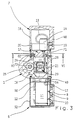
- the non-contact controlled sanitary fitting shown can be divided into five main components:
- a swivel spout 3 is attached to a central main housing 1, to which a base part 2 is attached at the bottom.
- Inlet channels 4 for hot and cold water penetrate the base part 2.
- Flexible water supply hoses 5 are screwed into these from below.
- two handle-like extensions 6 and 7 are attached to the main housing 1.
- the left handle-like extension 6 has only the external appearance, but not the function of a handle. It is only used to hold the electronic components of the non-contact valve.
- the optical entry and exit window 8 for that used to detect a user Infrared light shown.
- the window 8 is colored dark, so that its function as an optical window and the transmitter diode 9 behind it and the receiver diode 10 cannot be seen (see the section in FIG. 3).
- FIG. 3 it can be seen how the electronics 11 are accommodated inside the handle-like extension 6, which is supplied with the supply voltage via a cable 12 on the one hand and which is connected to a solenoid valve 14 via a further cable 13 in a manner yet to be described which controls the flow of water.
- the cable 12 is made via an axially parallel bore 15 in the main housing 1 or the base part 2 and an oblique bore 16 in the main housing 1 from the sanitary fitting.
- the right handle-like approach 7 is not only "handle-like" in the illustrated embodiment, so it not only sees a conventional sanitary fitting handle but actually has this function. It can be rotated about its horizontal axis to adjust the temperature of the mixed water flowing out of the sanitary fitting. In the case of a sanitary fitting which only releases water at a single temperature, the attachment 7 would also only be "similar" to the handle, ie it would not really perform the function of a handle, but would only pretend the presence of such a handle.
- FIGS. 4 and 5 have a larger scale than FIGS. 1 to 3.
- the cup-shaped outer housing 18 of the handle-like extension 7 is omitted in FIGS. 4 and 5 for the sake of clarity. It is fastened with a screw 19 to a cylindrical skirt 20 of the grater 17, as can be seen in FIG. 3.
- the outer housing 18 is rotated, the entire grater 17 is taken along, which changes the mixing ratio of cold and hot water in a manner to be described.
- the grater 17 is a one-piece molded part which projects into a cylindrical chamber 21 of the main housing 1 at the end facing away from the apron 20. Bores 22, 23 (see also FIG. 5), which pass obliquely through the main housing 1 and which communicate with the bores 4 in the base part 2 and through which cold and hot water can thus reach the cylindrical chamber 21, open into this chamber 21. Axially offset from the bores 22 and 23, another bore 24 of the main housing 1 opens into the cylindrical chamber 21, which is connected to a vertical bore 25 leading to the outlet 3. This can be seen in particular in FIG. 3.
- the inner end of the grater 17 used, the water flowing through the hoses 5, the channels 4, 22 and 23 into the cylindrical chamber 21 of the main housing 1 could flow directly through the bores 24 and 25 to the outlet 3.
- the setting of the mixing ratio of cold and hot water is done by an essentially cylindrical head 26 of the grater 17, in which an oblique groove 27 is incorporated.
- the groove 27 cuts the channels 22 and 23 in the main housing differently depending on the rotational position.
- FIG. 5 shows the position in which the same proportions of cold and hot water are obtained because the channels 22 and 23 both open to the same extent, namely half, into the groove 27. Water can therefore flow into the groove 27 from the channels 22 and 23.
- the groove 27 guides the mixing water into a recess 28 on the outer circumference of the head 26 of the grater 17, from where it can reach the end of the grater 17.
- An elastic cushion 79 is embedded in the lower region of the lateral surface of the grater head 26. If the grater 17 is turned to the full cold position, the cushion 79 lies over the mouth of the bore 22 supplying the hot water and closes it tightly. This prevents hot water losses.
- the further path of the mixed water arriving at the open end face of the grater 17 to the channel 24 and thus to the outlet 3 leads via the interior of the hollow head 26 of the grater 17, in which a pilot-controlled valve 29 is accommodated, and via a radial bore 44 in the grater 17 and an annular space 78, which lies between the wall of the chamber 21 and a reduced-diameter area of the grater 17.
- the annular space 78 becomes axial Direction limited by two O-rings 56 and 57, which are arranged in grooves on the outer surface of the grater 17.
- the pilot-controlled valve 29 comprises, as closing elements, a membrane 30 made of elastic material and a cage 31 made of rigid plastic, with which the membrane 30 cooperates. Although this is shown in one piece in the drawing, it can also be constructed in several parts.
- the elastic membrane 30 has the shape of two truncated cones, which are arranged in opposite directions, with beads 32, 33 projecting radially inwards on the axially opposite ends.
- the cage 31 comprises a central contact body 34 and at both axial ends a support ring 35 and 36, respectively, which cooperates with the bead 32, 33 of the elastic membrane 30 located there.
- the contact body 34 of the cage 31 is connected to the support rings 35, 36 via ribs 37 to form a unit.
- Cage 31 and membrane 30 tied thereon lie against a step in the interior of the grater and are releasably secured at the outer end by an insert ring 46 and a snap ring 47.
- the elastic membrane 30 is shaped such that it normally rests against the outside of the contact body 34 of the cage 31, ie without pressure from water from inside or outside. This is the closed state of the pilot-controlled valve 29, since then the water path through the interior of the grater 17 to the channel 24 is blocked by the contact body 34 and the membrane 29.
- the membrane 29 can move from the closed position shown into an open position by lifting off from the contact body 34 in the central region and resting against the wall of the cylindrical chamber 21 of the main housing 1. An annular space between the membrane 29 and the contact body 24 is released for flow.
- the inner space of the membrane 29 below the contact body 34 is connected to the outer space by a small radial compensating bore 38.
- This in turn communicates via an axially parallel channel 39 with a recess 40 on the outer end face of the grater 17, which is located radially inside the apron 20.
- the recess 40 is covered by the underside of the magnet coil 14 and sealed by an O-ring 45.
- a valve seat 41 is formed, which cooperates with a closing body 42.
- the closing body 42 normally closes the valve seat 41 and thus the access to an axially parallel channel 43, which leads to the radial bore 44 in the grater 17 and thus to the channel 24 in the main housing 1.
- the units held or formed by the handle-like extensions 6 and 7 are preassembled.
- the housing 52 has a thread at its open end, into which a ring 49 is screwed.
- Two screws 50, 51 extend transversely through the main housing 1 and are screwed with their threaded ends into threaded holes in the ring 49.
- the heads of the screws 50, 51 lie against countersinking in the right side surface of the main housing 1 in FIG. 1.
- the left handle-like extension 6 is thus attached to the main housing 1.
- the cable 12 is of course still run through the channels 15 and 16; the cable 13 is led through a channel 53 which completely penetrates the main housing 1 (cf. also FIG. 2) to the other side surface of the main housing 1.
- a cylindrical collar 54 at the inner end of the housing 52 protrudes into a groove on the left side surface of the main housing 1 in FIG. 1. This results in a visually pleasing transition between the handle-like extension 6 and the main housing 1.
- the grater 17 is provided with a groove 58 at that axial point at which the right-hand side face of the main housing 1 comes to rest in the installed state.
- a U-shaped fastening part 59 is inserted into this groove 58 from the side.
- This is screwed with three screws 60, 61 and 62 to the right side surface of the main housing 1 in FIG. 1.
- One of these screws, namely screw 60, is shown in FIGS. 4 and 5; all three screws can be seen in Figure 6, which represents a section along line VI-VI of Figure 3, at the level of the heads of the screws 60, 61, 62.
- the heads of the screws 60, 61, 62 are accessible through recesses 63, 64, which extend axially parallel through the outer part of the 17 up to the right end in FIG. 1. These recesses 63, 64 can alternately be aligned by rotating the grater 17 be brought with the heads of the screws 60, 61, 62 so that the screws 60, 61, 62 can be inserted here and tightened with a screwdriver.
- the angle through which the grater 17 can be rotated to adjust the temperature of the outflowing mixed water can be set in the following way:
- a further recess 65 is provided in the outer contour of the grater 17, but this has a larger diameter than the groove 58 and is not completely guided around the circumference of the grater 17 is. Rather, as can be seen in FIG. 6, a dovetail-shaped extension 66 projects radially outward from the "core" 67 of the grater 17. This dovetail-shaped extension 66 limits the rotatability of the grater 17 in FIG. 6 clockwise by coming into contact with the head of the screw 60.
- An arcuate elongated hole 68 penetrates the wall between the annular shoulder, which is formed by the recess 65 against the portion of the grater 17 which carries the apron 20, and the outer end wall of the grater 17, which is surrounded by the apron 20 and onto which the magnet coil 14 is also placed is.
- a screw 69 is guided through this slot 68 from the outside and holds a stop piece 70 on the aforementioned annular shoulder of the recess 65.
- the stop piece 70 runs radially from the "core" 67 of the grater 17 to the outer circumference of the annular shoulder formed by the recess 65. It limits the rotatability of the grater 17 counterclockwise by coming to bear against the head of the screw 60. The entire angle of rotation that the grater 17 can measure is evident from the variable position of the stop piece 70 in the arcuate elongated hole 68 determined.
- the head of the screw 19 in the handle 18 is covered with a window 48, the appearance of which corresponds to the window 8 in the handle-like attachment 6 on the left in FIG. Externally, as can be seen in FIG. 1, there is a completely symmetrical appearance.
- the main housing 1 is fastened to the base part 2 by a central screw 72 (FIG. 2), the head of which lies in the upper region in the bore 25 already mentioned, which leads the mixed water flowing from the cylindrical chamber 21 to the outlet 3.
- the downward waterway is blocked in FIG. 2 by a sealing ring 73, which is arranged between the head of the screw 72 and the ring shoulder of the bore 25 below it.
- a mounting piece 74 is screwed into the latter from above.
- the attachment piece 74 has a somewhat larger diameter in the upper region and is located here via O-rings on the inner wall of outlet 3. This is pushed over the mounting piece 74 to close to the upper end face of the main housing 1.
- a U-shaped fastening part 75 lies between the inner wall of the outlet 3 and the region of the fastening socket 74 which is reduced in diameter.
- the outlet 3 is fixed to it by means of a screw 76.
- the fastening part 75 bears with a projection 77 which extends in the axial direction against an annular step which connects the region of the fastening socket 74 which has a larger diameter with the region of smaller diameter.
- the outlet 3 is fixed in the axial direction.
- the axial projection 77 simultaneously acts as a limitation for the angle of rotation which the outlet 3 can measure with respect to the main housing 1.
Abstract
Description
Die Erfindung betrifft eine berührungslos gesteuerte Sanitärarmatur mit einem Gehäuse, in welchem untergebracht sind:
- a) im wesentlichen elektronische Bauelemente, insbesondere ein Sender, ein Empfänger und ein elektronischer Schaltkreis, welche berührungslos die Anwesenheit eines Benutzers in einem Erfassungsbereich feststellen und hiernach ein Ausgangssignal erzeugen;
- b) im wesentlichen mechanische Bauelemente, insbesondere ein elektrisch gesteuertes Ventil, welche in Abhängigkeit von dem Ausgangssignal der elektronischen Bauelemente und ggfs. anderen Einflußgrößen den Fluß des Wassers steuern.
- a) essentially electronic components, in particular a transmitter, a receiver and an electronic circuit, which contactlessly determine the presence of a user in a detection area and then generate an output signal;
- b) essentially mechanical components, in particular an electrically controlled valve, which control the flow of water as a function of the output signal of the electronic components and possibly other influencing variables.
Bei berührungslos gesteuerten Sanitärarmaturen geht das Bestreben allgemein dahin, alle Bauelemente, also sowohl die elektronischen als auch die mechanischen Bauelemente, in einem einheitlichen Gehäuse unterzubringen. Es ist dann also beispielsweise nicht mehr nötig, wie dies früher der Fall war, die den Wasserstrom steuernden elektrischen Ventile gesondert von der eigentlichen Armatur in den Zulaufleitungen anzubringen und die erforderlichen Verbindungs- und Anschlußkabel zu montieren. Bei bekannten berührungslos gesteuerten Sanitärarmaturen dieser Art ergibt sich nunmehr aufgrund der Vielzahl von unterzubringenden Bauelementen ein blockiges, nicht sehr gefälliges Aussehen. Außerdem sind sie im allgemeinen nicht sehr wartungsfreundlich.In the case of contactlessly controlled sanitary fittings, the general aim is to accommodate all the components, that is to say both the electronic and the mechanical components, in a single housing. It is then no longer necessary, for example, as was the case in the past, to mount the electrical valves controlling the water flow separately from the actual fitting in the feed lines and to mount the necessary connecting and connecting cables. In known non-contact controlled sanitary fittings of this type, a blocky, not very pleasing appearance now results due to the large number of components to be accommodated. In addition, they are generally not very easy to maintain.
Aufgabe der vorliegenden Erfindung ist es, eine berührungslos gesteuerte Sanitärarmatur der eingangs genannten Art wartungsfreundlich auszugestalten, wobei ihr gleichzeitig ein gefälliges Erscheinungsbild gegeben werden soll.The object of the present invention is to design a contactlessly controlled sanitary fitting of the type mentioned at the outset in a maintenance-friendly manner, while at the same time giving it a pleasing appearance.
Diese Aufgabe wird erfindungsgemäß dadurch gelöst, daß
- c) das Gehäuse ein die Wasserkanäle enthaltendes Hauptgehäuse und zwei symmetrisch zu einer Mittelebene lösbar angefügte griffähnliche Ansätze mit jeweils einem im wesentlichen becherförmigen Gehäuse umfaßt;
- d) alle elektronischen Bauelemente baueinheitlich von einem der griffähnlichen Ansätze gehalten und zumindest teilweise in dessen becherförmigem Gehäuse untergebracht sind;
- e) alle mechanischen Bauelemente baueinheitlich von dem anderen der griffähnlichen Ansätze gehalten und zumindest teilweise in dessen becherförmigem Gehäuse untergebracht sind.
- c) the housing comprises a main housing containing the water channels and two handle-like projections, each detachably attached symmetrically to a central plane, each with an essentially cup-shaped housing;
- d) all electronic components are structurally held by one of the handle-like approaches and are at least partially housed in its cup-shaped housing;
- e) all mechanical components are structurally held by the other of the handle-like approaches and are at least partially housed in its cup-shaped housing.
In ästhetischer Richtung erreicht die Erfindung das von ihr gesetzte Ziel in folgender Weise: Es sind allgemein sogenannte Zweigriffarmaturen den Benutzern bekannt, bei denen seitlich an das Armaturengehäuse zwei Griffe zur Einstellung des Warm- bzw. Kaltwasserstromes angefügt sind. Die Benutzer haben sich an das Erscheinungsbild derartiger Armaturen, deren Design eine sehr hohe Qualität erreicht hat, gewöhnt. Mit der Erfindung wird nunmehr das äußere Erscheinungsbild derartiger bekannter und ästhetischer Zweigriffarmaturen für eine berührungslos gesteuerte Sanitärarmatur simuliert. Was von dem Betrachten als "Griff" empfunden und ästhetisch toleriert wird, ist tatsächlich eine Gehäuseerweiterung, in welcher Bauelemente untergebracht sind. Hierdurch wird in dem mittleren Hauptgehäuse, welches vom Benutzer mit dem ihm bekannten Armaturengehäuse gleichgesetzt wird, Raum eingespart, so daß dieses schlanker und ästhetischer gehalten werden kann.In terms of aesthetics, the invention achieves the goal it has set in the following way: so-called two-handle fittings are generally known to users, in which two handles for adjusting the hot or cold water flow are attached to the side of the fitting housing. The users have got used to the appearance of such fittings, the design of which has reached a very high quality. With the invention, the external appearance of such known and aesthetic two-handle fittings for a non-contact controlled sanitary fitting is now simulated. What is perceived by the viewer as a "grip" and aesthetically tolerated is actually a housing extension in which components are housed. This saves space in the central main housing, which the user equates with the fitting housing known to him, so that it can be kept slimmer and more aesthetically pleasing.
Die Wartungsfreundlichkeit erreicht die vorliegende Erfindung dadurch, daß die drei Hauptkomponenten des Gehäuses jeweils nur solche Bauelemente enthalten, die "in eine Disziplin" fallen: An einem der seitlichen Ansätze sind alle elektronischen Bauelemente als Baueinheit zusammengefaßt. Diese Baueinheit fällt in das Zuständigkeitsgebiet des Elektronikers; sie kann von diesem zunächst werksseitig erstellt, dann aber auch ggf. gewartet, repariert oder insgesamt ausgetauscht werden. In dem mittleren Hauptgehäuse befinden sich alle wasserführenden Kanäle, die im allgemeinen einer besonderen Wartung nicht bedürfen. Im zweiten griffähnlichen Ansatz dagegen sind wiederum zu einer Baueinheit alle mechanischen Bauelemente zusammengefaßt, die ebenfalls zu Wartungszwecken insgesamt von der Sanitärarmatur abgenommen werden können und dann von dem in diesem Falle zuständigen Sanitärfachmann ohne weiteres repariert, im gegebenen Fall auch als Ganzes ausgetauscht werden können.The present invention achieves ease of maintenance by virtue of the fact that the three main components of the housing each contain only those components which fall "in one discipline": all of the electronic components are combined as one unit on one of the side approaches. This unit is the responsibility of the electronics engineer; It can initially be created by the manufacturer, but then it can also be serviced, repaired or replaced as a whole. In the middle main housing there are all water-carrying channels that generally do not require special maintenance. In the second handle-like approach, on the other hand, all mechanical components are combined in one unit, which can also be removed from the sanitary fitting for maintenance purposes and then easily repaired by the sanitary specialist responsible in this case, and can also be replaced as a whole if necessary.
In vielen Fällen genügt es, wenn der griffähnliche Ansatz an dem Hauptgehäuse unverdrehbar befestigt ist. Der griffähnliche Ansatz dient auf diese Weise tatsächlich nur als Gehäuseerweiterung, in dem zusätzlicher Raum für Bauelemente zur Verfügung steht. Insbesondere derjenige griffähnliche Ansatz, in welchem die elektronischen Bauelemente untergebracht sind, wird im allgemeinen unverdrehbar sein.In many cases, it is sufficient if the handle-like attachment is non-rotatably attached to the main housing. In this way, the handle-like approach actually only serves as a housing extension in which additional space is available for components. In particular, the handle-like approach in which the electronic components are housed will generally be non-rotatable.
Die Befestigung eines unverdrehbaren Ansatzes geschieht zweckmäßigerweise so, daß in dem offenen Ende von dessen Gehäuse ein Befestigungsring lösbar befestigt ist, und daß der Befestigungsring an einer Seitenfläche des Hauptgehäuses angeschraubt ist.The attachment of a non-rotatable approach expediently so that in the open end of it Housing a mounting ring is releasably attached, and that the mounting ring is screwed to a side surface of the main housing.
Aus Zugänglichkeitsgründen erstrecken sich dabei vorteilhafterweise die Schrauben für den Befestigungsring quer durch das Hauptgehäuse hindurch. Der unverdrehbare Ansatz wird also mit diesen Schrauben von der gegenüberliegenden Seite her am Hauptgehäuse befestigt, solange der dort anzubringende griffähnliche Ansatz noch nicht montiert ist.For reasons of accessibility, the screws for the fastening ring advantageously extend across the main housing. The non-rotatable attachment is thus attached to the main housing from the opposite side with these screws, as long as the handle-like attachment to be attached there has not yet been installed.
Mindestens einer der griffähnlichen Ansätze kann aber auch verdrehbar sein und insoweit als echter Griff dienen. Nicht alle Funktionen bei einer berührungslos gesteuerten Armatur werden tatsächlich berührungslos durchgeführt. Es ist durchaus üblich und auch aus hygienischen Gründen hinnehmbar, daß selten benötigte Funktionsänderungen, beispielsweise die Einstellung der Temperatur des ausfließenden Wassers, von Hand vorgenommen werden. Dies kann mit einem als echtem Griff gestalteten, verdrehbaren griffähnlichen Ansatz nach der vorliegenden Erfindung geschehen, wobei dann selbstverständlich dieser verdrehbare Ansatz alle an ihm befestigten Bauelemente bei der Verdrehung mitführt.At least one of the handle-like approaches can also be rotated and serve as a real handle. Not all functions in a contactlessly controlled valve are actually carried out without contact. It is quite common and also acceptable for hygienic reasons that function changes that are seldom required, for example the setting of the temperature of the outflowing water, are carried out by hand. This can be done with a rotatable handle-like extension designed as a real handle according to the present invention, in which case, of course, this rotatable extension carries all the components attached to it during the rotation.
Bei dieser häufigsten Ausgestaltung mit verdrehbarem Ansatz hält dieser vorteilhafterweise einen Drehkolben, der mit seinem den Kalt- und Warmwasserstrom regelnden Bereich in eine Kammer des Hauptgehäuses hineinragt.In this most common embodiment with a rotatable attachment, the latter advantageously holds a rotary piston which, with its region regulating the cold and hot water flow, projects into a chamber of the main housing.
Besonders raumsparend ist in diesem Zusammenhang, wenn der Drehkolben als Hohlkolben ausgebildet ist und zumindest die Schließelemente des elektrisch gesteuerten Ventiles innerhalb des Hohlkolbens angeordnet sind.In this context, it is particularly space-saving if the rotary piston is designed as a hollow piston and at least the closing elements of the electrically controlled valve are arranged within the hollow piston.
Nach einem besonderen Merkmal der vorliegenden Erfindung ist der verdrehbare griffähnliche Ansatz an das Hauptgehäuse mittels eines U-förmigen Befestigungsteiles angeschraubt, welches in eine Nut an einem mechanischen, von dem verdrehbaren Ansatz gehaltenen Bauelement eingreift. Durch das U-förmige Befestigungsteil wird also der gesamte verdrehbare griffähnliche Ansatz in axialer Richtung fixiert. Da diese Befestigungsart ausschließlich auf derjenigen Seitenfläche des Hauptgehäuses geschieht, wo der verdrehbare griffähnliche Ansatz angebracht werden soll, eignet sie sich besonders zur Kombination mit der oben geschilderten Befestigungsart für einen unverdrehbaren griffähnlichen Ansatz, die mit sich durch das gesamte Hauptgehäuse hindurch erstreckende Befestigungsschrauben erfolgt.According to a special feature of the present invention, the rotatable handle-like extension is screwed to the main housing by means of a U-shaped fastening part which engages in a groove on a mechanical component held by the rotatable extension. The entire rotatable handle-like attachment is thus fixed in the axial direction by the U-shaped fastening part. Since this type of fastening only occurs on the side surface of the main housing where the rotatable handle-like extension is to be attached, it is particularly suitable for combination with the above-described type of fastening for a non-rotatable handle-like extension, which is carried out with fastening screws extending through the entire main housing.
Selbstverständlich muß bei der Befestigungsart mit U-förmigem Befestigungsstück Sorge dafür getragen werden, daß die Befestigungsschrauben tatsächlich zugänglich sind. Hierzu kann das die Nut aufweisende Bauelement zu einer seitlichen Stirnfläche führende Ausnehmungen aufweisen, die in Fluchtung mit den Befestigungsschrauben für das U-förmige Befestigungsteil gebracht werden können. Der verdrehbare Ansatz braucht also nur ein wenig verdreht zu werden, damit über die genannten Ausnehmungen die Befestigungsschrauben für einen Schraubenzieher zugänglich sind.Of course, care must be taken with the type of fastening with a U-shaped fastening piece that the fastening screws are actually accessible. For this purpose, the component having the groove can have recesses leading to a lateral end face, which can be brought into alignment with the fastening screws for the U-shaped fastening part. The rotatable approach only needs to be rotated a little so that the fastening screws for a screwdriver are accessible via the recesses mentioned.
Der verdrehbare Ansatz sollte mit einer Drehwinkelbegrenzung versehen sein. Hierzu kann ein an ihm gehaltertes mechanisches Bauelement einen Einstich aufweisen, der einen radial von einem Kern des Bauelements vorspringenden Ansatz bildet, wobei dieser Ansatz durch Anlage an einem stationären Teil die Verdrehbarkeit des Ansatzes zumindest in einem Drehsinne begrenzt.The rotatable attachment should be provided with a rotation angle limitation. For this purpose, a mechanical component held on it can have a recess which forms a projection projecting radially from a core of the component, this projection limiting the rotatability of the projection at least in one direction of rotation by contact with a stationary part.
Der Drehwinkel sollte insbesondere in der Richtung, welche einer Temperaturhöhung entspricht, verstellbar sein. Hierzu kann an einer Ringschulter des Einstiches in unterschiedlichen Winkelpositionen ein Anschlagstück befestigt sein, welches durch Anlage an einem stationären Teil die Verdrehbarkeit des Ansatzes in diesem Drehsinne begrenzt.The angle of rotation should be adjustable in particular in the direction which corresponds to a temperature increase. For this purpose, a stop piece can be attached to an annular shoulder of the recess in different angular positions, which limits the rotatability of the attachment in this direction of rotation by contact with a stationary part.
Als stationäres Teil kann einfach eine Befestigungsschraube zur Halterung des verdrehbaren Ansatzes am Hauptgehäuse dienen.As a stationary part, a fastening screw can simply be used to hold the rotatable attachment on the main housing.
Die becherförmigen Gehäuse der griffähnlichen Ansätze greifen vorteilhafterweise mit ihren offenen Enden bzw. mit einem dieses verlängernden Kragen in eine Nut an der benachbarten Seitenfläche des Hauptgehäuses ein. Dies gibt einen optisch gefälligen Übergang zwischen den beiden seitlichen griffähnlichen Ansätzen und dem Hauptgehäuse, der zudem für den Betrachter nicht mehr erkennen läßt, ob nun der jeweilige griffähnliche Ansatz verdrehbar ist oder nicht.The cup-shaped housings of the handle-like projections advantageously engage with their open ends or with a collar that extends this into a groove on the adjacent side surface of the main housing. This gives a visually pleasing transition between the two side handle-like approaches and the main housing, which moreover no longer reveals to the viewer whether the respective handle-like approach can now be rotated or not.
Nach einem weiteren Merkmal der Erfindung ist das Hauptgehäuse am Sockelteil durch eine zentrale Schraube befestigt.According to a further feature of the invention, the main housing is attached to the base part by a central screw.
Dabei sollten die Trennstellen zwischen den Zulaufkanälen und den Bohrungen mit geeigneten Dichtungen versehen und der Kopf der zentralen Schraube durch einen Dichtring gegen das Hauptgehäuse abgedichtet sein.The separating points between the inlet channels and the bores should be provided with suitable seals and the head of the central screw sealed with a sealing ring against the main housing.
Ein Ausführungsbeispiel der Erfindung wird nachfolgend anhand der Zeichnung näher erläutert; es zeigen
- Figur 1:
- die Vorderansicht einer berührungslos gesteuerten Sanitärarmatur;
- Figur 2:
- einen Schnitt gemäß Linie II-II von
Figur 1; - Figur 3:
- einen Schnitt gemäß Linie III-III von
Figur 1; - Figur 4:
- einen Ausschnitt aus
Figur 3 in größerem Maßstab; - Figur 5:
- eine Ansicht, ähnlich der
Figur 4, jedoch geschnitten gemäß Pfeil V in Figur 2 (Drehkolben nicht geschnitten); - Figur 6:
- einen Schnitt gemäß Linie VI-
VI von Figur 3 in vergrößertem Maßstab.
- Figure 1:
- the front view of a non-contact controlled sanitary fitting;
- Figure 2:
- a section along line II-II of Figure 1;
- Figure 3:
- a section along line III-III of Figure 1;
- Figure 4:
- a section of Figure 3 on a larger scale;
- Figure 5:
- a view similar to Figure 4, but cut according to arrow V in Figure 2 (rotary piston not cut);
- Figure 6:
- a section along line VI-VI of Figure 3 on an enlarged scale.
Wie der Figur 1 der Zeichnung zu entnehmen ist, läßt sich die dargestellte berührungslos gesteuerte Sanitärarmatur zwanglos in fünf Hauptkomponenten unterteilen:As can be seen in FIG. 1 of the drawing, the non-contact controlled sanitary fitting shown can be divided into five main components:
Auf ein zentrales Hauptgehäuse 1, an welches unten ein Sockelteil 2 angesetzt ist, ist ein Schwenkauslauf 3 aufgesteckt. Zulaufkanäle 4 für Warmund Kaltwasser (einer in Figur 2 gestrichelt angedeutet) durchsetzen das Sockelteil 2. In diese sind von unten her flexible Wasserzuführungsschläuche 5 eingeschraubt.A
Symmetrisch zu der in Figur 1 angedeuteten Schnittebene II-II sind an das Hauptgehäuse 1 zwei griffähnliche Ansätze 6 und 7 angefügt.Symmetrical to the section plane II-II indicated in FIG. 1, two handle-
Der linke griffähnliche Ansatz 6 hat nur das äußere Erscheinungsbild, nicht jedoch die Funktion eines Griffes. Er dient ausschließlich dazu, die elektronischen Baukomponenten der berührungslos gesteuerten Armatur aufzunehmen. In Figur 1 sowie Figur 3 ist das optische Ein- und Austrittsfenster 8 für das zur Erfassung eines Benutzers verwendete Infrarotlicht dargestellt. Das Fenster 8 ist dunkel eingefärbt, so daß seine Funktion als optisches Fenster und die dahinter liegende Sendediode 9 sowie die Empfangsdiode 10 nicht erkennbar sind (vergl. den Schnitt in Figur 3). In Figur 3 ist zu erkennen, wie im Inneren des griffähnlichen Ansatzes 6 die Elektronik 11 untergebracht ist, welcher zum einen über ein Kabel 12 die Versorgungsspannung zugeführt wird und die zum anderen über ein weiteres Kabel 13 in noch zu beschreibender Weise mit einem Magnetventil 14 verbunden ist, welches den Wasserstrom steuert. Das Kabel 12 ist über eine achsparallele Bohrung 15 im Hauptgehäuse 1 bzw. dem Sockelteil 2 sowie eine Schrägbohrung 16 im Hauptgehäuse 1 aus der Sanitärarmatur ausgeführt.The left handle-
Die Anordnung ist offensichtlich so, daß in dem griffähnlichen Ansatz 6 all diejenigen Bauelemente zu einer Einheit zusammengefaßt sind, welche als "elektronisch" in dem Sinne bezeichnet werden können, daß sie der elektrischen Erfassung eines Benutzers vor der Sanitärarmatur und der Erzeugung von solchen Signalen dienen, mit denen ein Magnetventil angesteuert werden kann.The arrangement is obviously such that in the handle-
Der rechte griffähnliche Ansatz 7 ist beim dargestellten Ausführungsbeispiel nicht nur "griffähnlich", sieht also nicht nur einem üblichen Sanitärarmaturen-Griff sondern besitzt tatsächlich diese Funktion. Er läßt sich nämlich zur Einstellung der Temperatur des aus der Sanitärarmatur ausfließenden Mischwassers um seine horizontal liegende Achse verdrehen. Bei einer Sanitärarmatur, die ausschließlich Wasser einer einzigen Temperatur abgibt, wäre auch der Ansatz 7 nur griff"ähnlich", würde also die Funktion eines Griffes nicht wirklich ausüben sondern nur das Vorhandensein eines solchen Griffes optisch vortäuschen.The right handle-
In dem griffähnlichen Ansatz 7 sind all diejenigen Bauelemente als Einheit untergebracht bzw. montiert, welche der Steuerung des Wasserstromes dienen und in diesem Sinne als "mechanisch" betrachtet werden können. Zu diesen mechanischen Bauelementen gehören insbesondere ein magnetisch betätigtes Pilotventil, dessen Aufbau weiter unten näher erläutert wird, sowie einen mit diesem baulich vereinigten Drehkolben 17, auch "Reiber" genannt, zur Temperatureinstellung.In the handle-
Zur genaueren Beschreibung dessen, was in bzw. an dem griffähnlichen Ansatz 7 untergebracht ist, wird nunmehr auf die Figuren 4 und 5 Bezug genommen, welche gegenüber den Figuren 1 bis 3 einen größeren Maßstab aufweisen. Das becherförmige äußere Gehäuse 18 des griffähnlichen Ansatzes 7 ist in den Figuren 4 und 5 der Übersichtlichkeit halber weggelassen. Es ist mit einer Schraube 19 an einer zylindrischen Schürze 20 des Reibers 17 befestigt, wie dies der Figur 3 zu entnehmen ist. Beim Verdrehen des äußeren Gehäuses 18 wird somit der gesamte Reiber 17 mitgenommen, was in noch zu beschreibender Weise das Mischungsverhältnis von Kalt- und Warmwasser verändert.For a more detailed description of what is accommodated in or on the handle-
Der Reiber 17 ist ein einstückiges Formteil, welches an dem von der Schürze 20 abgewandten Ende in eine zylindrische Kammer 21 des Hauptgehäuses 1 hineinragt. In diese Kammer 21 münden schräg durch das Hauptgehäuse 1 hindurchgeführte Bohrungen 22, 23 (vergl. auch Figur 5), welche mit den Bohrungen 4 im Sockelteil 2 kommunizieren und über die somit Kalt- und Warmwasser in die zylindrische Kammer 21 gelangen kann. Axial gegenüber den Bohrungen 22 und 23 versetzt mündet in die zylindrische Kammer 21 eine weitere Bohrung 24 des Hauptgehäuses 1, welche mit einer vertikalen, zum Auslauf 3 führenden Bohrung 25 in Verbindung steht. Dies ist insbesondere der Figur 3 zu entnehmen. Wäre also in die zylindrische Kammer 21 nicht das innere Ende des Reibers 17 eingesetzt, so könnte das über die Schläuche 5, die Kanäle 4, 22 und 23 in die zylindrische Kammer 21 des Hauptgehäuses 1 einströmende Wasser direkt über die Bohrungen 24 und 25 zum Auslauf 3 strömen.The
Die Einstellung des Mischungsverhältnisses von Kalt- und Warmwasser geschieht durch einen im wesentlichen zylindrischen Kopf 26 des Reibers 17, in welche eine schräg verlaufende Nut 27 eingearbeitet ist. Die Nut 27 schneidet je nach Drehstellung die Kanäle 22 und 23 im Hauptgehäuse unterschiedlich an. In Figur 5 ist diejenige Stellung dargestellt, in welcher gleiche Anteile von Kalt- und Warmwasser erhalten werden, weil die Kanäle 22 und 23 sich beide in gleichem Maße, nämlich zur Hälfte, in die Nut 27 hinein öffnen. Es kann daher Wasser aus den Kanälen 22 und 23 in die Nut 27 hineinströmen. Die Nut 27 führt das sich vermischende Wasser in einen Rücksprung 28 am Außenumfang des Kopfes 26 des Reibers 17, von wo es zur Stirnseite des Reibers 17 gelangen kann.The setting of the mixing ratio of cold and hot water is done by an essentially
Im unteren Bereich der Mantelfläche des Reiberkopfes 26 ist ein elastisches Kissen 79 eingelassen. Wird der Reiber 17 in die volle Kaltstellung verdreht, liegt das Kissen 79 über der Mündung der das Warmwasser zuführenden Bohrung 22 und schließt diese dicht ab. Hierdurch werden Warmwasserverluste vermieden.An
Der weitere Weg des an der offenen Stirnseite des Reibers 17 angelangten Mischwassers zum Kanal 24 und damit zum Auslauf 3 führt über den Innenraum des hohlen Kopfes 26 des Reibers 17, in welchem ein pilotgesteuertes Ventil 29 untergebracht ist, sowie über eine radiale Bohrung 44 im Reiber 17 und einen Ringraum 78, der zwischen der Wand der Kammer 21 und einem im Durchmesser verkleinerten Bereich des Reibers 17 liegt. Der Ringraum 78 wird in axialer Richtung durch zwei O-Ringe 56 und 57 begrenzt, die in Nuten auf der Mantelfläche des Reibers 17 angeordnet sind.The further path of the mixed water arriving at the open end face of the
Ohne das pilotgesteuerte Ventil 29 könnte das an der inneren Stirnseite des Kopfes 26 des Reibers 17 angekommene Wasser frei durch den Innenraum des Reibers 17 zum Kanal 24 strömen.Without the pilot-controlled
Das pilotgesteuerte Ventil 29 umfaßt als Schließelemente eine Membran 30 aus elastischen Material sowie einen Käfig 31 aus starren Kunststoff, mit welchem die Membran 30 zusammenwirkt. Dieser ist in der Zeichnung zwar einstückig dargestellt, kann aber auch mehrteilig aufgebaut sein.The pilot-controlled
Die elastische Membran 30 hat die Form zweier gegensinnig aneinandergesetzter Kegelstümpfe, wobei an den axial gegenüberliegenden Enden radial nach innen ragende Wulste 32, 33 angeformt sind.The
Der Käfig 31 umfaßt einen mittleren Anlagekörper 34 sowie an beiden axialen Enden jeweils einen Stützring 35 bzw. 36, welcher mit dem dort befindlichen Wulst 32, 33 der elastischen Membran 30 zusammenwirkt. Der Anlagekörper 34 des Käfigs 31 ist über Rippen 37 mit den Stützringen 35, 36 zu einer Einheit verbunden.The
Käfig 31 und auf diesen aufgeknüpfte Membran 30 liegen an einer Stufe im Innenraum des Reibers an und sind am außenliegenden Ende durch einen Beilagering 46 und einen Sprengring 47 lösbar gesichert.
Die elastische Membran 30 ist so geformt, daß sie sich normalerweise, also ohne Druckbeaufschlagung durch Wasser von innen oder außen, an die Außenseite des Anlagekörpers 34 des Käfigs 31 anlegt. Dies ist der Schließzustand des pilotgesteuerten Ventiles 29, da dann der Wasserweg durch den Innenraum des Reibers 17 zum Kanal 24 durch den Anlagekörper 34 und die Membran 29 versperrt ist.The
Die Membran 29 kann sich aus der dargestellten Schließstellung in eine Öffnungsstellung bewegen, indem sie sich im mittleren Bereich von dem Anlagekörper 34 abhebt und gegen die Wandung der zylindrischen Kammer 21 des Hauptgehäuses 1 anlegt. Dabei wird ein Ringraum zwischen der Membran 29 und dem Anlagekörper 24 zur Durchströmung freigegeben.The
Diese Bewegung der Membran 30 geschieht unter den Einfluß der Drücke, die radial innerhalb und radial außerhalb von ihr existieren. Diese Vorgänge sind an und für sich bekannt und brauchen hier nicht näher erläutert zu werden. Im vorliegenden Zusammenhang genügt, folgendes zu wissen:This movement of the
Der unterhalb des Anlagekörpers 34 liegende Innenraum der Membran 29 ist durch eine kleine radiale Ausgleichsbohrung 38 mit dem Außenraum verbunden. Dieser wiederum kommuniziert über einen achsparallelen Kanal 39 mit einer Ausnehmung 40 an der äußeren, radial innerhalb der Schürze 20 liegenden Stirnseite des Reibers 17. Die Ausnehmung 40 ist von der Unterseite der Magnetspule 14 abgedeckt und durch einen O-Ring 45 abgedichtet. Am Boden der Ausnehmung 40 ist ein Ventilsitz 41 ausgeformt, welcher mit einem Schließkörper 42 zusammenwirkt. Der Schließkörper 42 verschließt normalerweise den Ventilsitz 41 und damit den Zugang zu einen achsparallelen Kanal 43, welcher zu der Radialbohrung 44 im Reiber 17 und damit zum Kanal 24 im Hauptgehäuse 1 führt.The inner space of the
Solange der Schließkörper 42 den Ventilsitz 41 verschließt, wie dies in Figur 4 gezeigt ist, ist die von außen auf die elastische Membran 30 wirkende Druckkraft größer als die im Innenraum der Membran 29 herrschende resultierende Druckkraft. Die Membran 30 bleibt daher in Kontakt mit dem Außenumfang des Anlagekörpers 34 des Käfigs 31; das pilotgesteuerte Ventil 29 ist geschlossen.As long as the closing
Wird jedoch die Spule 14 des pilotgesteuerten Ventiles bestromt, hebt der Schließkörper 42 von Ventilsitz 41 ab. Dies hat eine Veränderung der auf die Membran 30 wirkenden Drücke in dem Sinne zur Folge, daß die Membran 30 im mittleren Bereich von dem Anlagekörper 34 abhebt und sich in die Öffnungsstellung begibt, in welcher sie an der Innenwandung des Kopfes 26 des Reibers 17 anliegt.However, if the
Bei der Montage der berührungslos gesteuerten Sanitärarmatur werden zunächst die von den griffähnlichen Ansätzen 6 und 7 gehaltenen bzw. gebildeten Einheiten vormontiert.When assembling the non-contact controlled sanitary fitting, the units held or formed by the handle-
Für den griffähnlichen Ansatz 6 bedeutet dies, daß in dessen Gehäuse 52 vom offenen Ende her die Sendediode 9 sowie die Empfangsdiode 10 und die Elektronik 11 eingeführt und befestigt werden. Das Gehäuse 52 trägt an seinem offenen Ende ein Gewinde, in welches ein Ring 49 eingeschraubt wird. Zwei Schrauben 50, 51 (vergl. auch Figur 2) erstrecken sich quer durch das Hauptgehäuse 1 hindurch und sind mit ihren Gewindeende in Gewindebohrungen des Ringes 49 eingedreht. Die Köpfe der Schrauben 50, 51 legen sich dabei gegen eine Versenkung in der in Figur 1 rechten Seitenfläche des Hauptgehäuses 1 an. Der linke griffähnliche Ansatz 6 ist damit an dem Hauptgehäuse 1 befestigt. Durch die Verwendung des Ringes 49 und der Schrauben 50, 51 ist es möglich, die Winkelorientierung des Gehäuses 52 und damit die Ausrichtung des optischen Fensters 8 genau festzulegen, was nicht ohne weiteres möglich wäre, wenn das Gehäuse 52 des linken griffähnlichen Ansatzes 6 einfach mit dem Ende in das Hauptgehäuse 1 eingeschraubt wäre.For the handle-
Vor der endgültigen Festlegung des griffähnlichen Ansatzes 6 an dem Hauptgehäuse 1 wird selbstverständlich noch das Kabel 12 durch die Kanäle 15 und 16 ausgeführt; das Kabel 13 wird durch einen das Hauptgehäuse 1 vollständig durchsetzenden Kanal 53 (vergl. auch Figur 2) zur anderen Seitenfläche des Hauptgehäuses 1 hindurchgeführt.Before the final definition of the handle-
Ein zylindrischer Kragen 54 am inneren Ende des Gehäuses 52 ragt in eine Nut an der in Figur 1 linken Seitenfläche des Hauptgehäuses 1. Hierdurch ergibt sich ein optisch gefälliger Übergang zwischen dem griffähnlichen Ansatz 6 und dem Hauptgehäuse 1.A
Die Befestigung des in Figur 1 rechten griffähnlichen Ansatzes 7, der tatsächlich ein echter Griff ist, geschieht auf folgende Weise (die nachfolgende Beschreibung nimmt insbesondere Bezug auf die Figuren 3 bis 6):The attachment of the handle-
An derjenigen axialen Stelle, an welcher im eingebauten Zustand die in Figur 1 rechte Seitenfläche des Hauptgehäuses 1 zu liegen kommt, ist der Reiber 17 mit einer Nut 58 versehen. In diese Nut 58 ist von der Seite her ein U-förmiges Befestigungsteil 59 eingeschoben. Dieses ist mit drei Schrauben 60, 61 und 62 an der in Figur 1 rechte Seitenfläche des Hauptgehäuses 1 festgeschraubt. Eine dieser Schrauben, nämlich die Schraube 60, ist in den Figuren 4 und 5 dargestellt; alle drei Schrauben sind in Figur 6 erkennbar, welche einen Schnitt gemäß Linie VI-VI von Figur 3, in Höhe der Köpfe der Schrauben 60, 61, 62 darstellt. Die Köpfe der Schrauben 60, 61, 62 sind durch Ausnehmungen 63, 64 zugänglich, die sich achsparallel durch den äußeren Teil des 17 bis zu der in Figur 1 rechten Stirnseite hindurch erstrecken. Diese Ausnehmungen 63, 64 können durch Verdrehen des Reibers 17 abwechselnd in Fluchtung mit den Köpfen der Schrauben 60, 61, 62 gebracht werden, so daß die Schrauben 60, 61, 62 hier eingeführt und mit einem Schraubenzieher festgedreht werden können.The
Der Winkel, um welchen der Reiber 17 zur Einstellung der Temperatur des ausfließenden Mischwassers verdreht werden kann, ist auf folgende Weise einstellbar:The angle through which the
Unmittelbar an die Außenseite der Nut 58 angrenzend (in Figur 4 also oberhalb von dieser) ist in der Außenkontur des Reibers 17 eine weiterer Einstich 65 vorgesehen, welcher aber einen größeren Durchmesser als die Nut 58 aufweist und nicht vollständig um den Umfang des Reibers 17 herumgeführt ist. Vielmehr ragt, wie der Figur 6 zu entnehmen ist, vom "Kern" 67 des Reibers 17 ein schwalbenschwanzförmiger Ansatz 66 radial nach außen. Dieser schwalbenschwanzförmige Ansatz 66 begrenzt die Verdrehbarkeit des Reibers 17 in Figur 6 im Uhrzeigersinn, indem er in Anlage an den Kopf der Schraube 60 kommt.Immediately adjacent to the outside of the groove 58 (above it in FIG. 4), a
Ein bogenförmiges Langloch 68 durchsetzt die Wand zwischen der Ringschulter, welche von dem Einstich 65 gegen den die Schürze 20 tragenden Teilbereich des Reibers 17 gebildet wird, und der äußeren, von der Schürze 20 umgebenen Stirnwand des Reibers 17, auf welche auch die Magnetspule 14 aufgesetzt ist. Durch dieses Langloch 68 ist von außen her eine Schraube 69 geführt, welche an der erwähnten Ringschulter des Einstichs 65 ein Anschlagstück 70 festhält. Das Anschlagstück 70 verläuft radial vom "Kern" 67 des Reibers 17 zum Außenumfang der von dem Einstich 65 gebildeten Ringschulter. Es begrenzt die Verdrehbarkeit des Reibers 17 gegen den Uhrzeigersinn, indem es gegen den Kopf der Schraube 60 zur Anlage kommt. Ersichtlich ist der gesamte Drehwinkel, den der Reiber 17 durchmessen kann, durch die variable Position des Anschlagstückes 70 im bogenförmigen Langloch 68 bestimmt.An arcuate
Wenn der Reiber 17 mit dem in diesem untergebrachten pilotgesteuerten Ventil 29 und der dieses betätigenden Magnetspule 14 mittels des U-förmigen Befestigungsteiles 59 und der Schrauben 60 bis 62 am Hauptgehäuse 1 festgelegt ist, wird das Gehäuse 18 auf die Schürze 20 des Reibers 17 aufgeschoben und dort mit einer Schraube 19 befestigt. Ein mit dem Gehäuse 18 verschraubter zylindrischer Kragen 71, der auch mit dem Gehäuse 18 einstückig sein könnte, greift dabei in eine Nut in der in Figur 1 rechten Seitenfläche des Hauptgehäuses 1 ein. Die Verhältnisse sind insoweit identisch mit der Art, wie das äußere Gehäuse 52 des in Figur 1 linken griffähnlichen Ansatzes 6 in eine Nut an der linken Seitenfläche des Hauptgehäuses 1 eingreift.When the
Abschließend wird der Kopf der Schraube 19 im Griff 18 mit einem Fenster 48 verdeckt, dessen Aussehen dem Fenster 8 im in Figur 1 linken griffähnlichen Ansatz 6 entspricht. Äußerlich bietet sich somit, wie der Figur 1 zu entnehmen ist, ein völlig symmetrisches Erscheinungsbild.Finally, the head of the
Das Hauptgehäuse 1 ist am Sockelteil 2 durch eine zentrale Schraube 72 befestigt (Figur 2), deren Kopf im oberen Bereich in der bereits erwähnten Bohrung 25 liegt, welche das von der zylindrischen Kammer 21 fließende Mischwasser zum Auslauf 3 führt. Der Wasserweg nach unten ist in Figur 2 durch einen Dichtring 73 versperrt, welcher zwischen dem Kopf der Schraube 72 und der darunter liegenden Ringschulter der Bohrung 25 angeordnet ist.The
Zur Befestigung des Auslaufes 3 am Hauptgehäuse 1 ist in letzteres von oben her ein Befestigungsstutzen 74 eingeschraubt. Der Befestigungsstutzen 74 besitzt im oberen Bereich einen etwas größeren Durchmesser und liegt hier über O-Ringe an der Innenwand des Auslaufes 3 an. Dieser ist über den Befestigungsstutzen 74 bis nahe an die obere Stirnseite des Hauptgehäuses 1 geschoben. Ein U-förmiges Befestigungsteil 75 liegt zwischen der Innenwand des Auslaufes 3 und dem im Durchmesser verkleinerten Bereich des Befestigungsstutzens 74. An ihm ist der Auslauf 3 mittels einer Schraube 76 festgelegt. Das Befestigungsteil 75 liegt mit einen sich in axialer Richtung erstreckenden Vorsprung 77 an einer Ringstufe an, welche den in Durchmesser erweiteren Bereich des Befestigungsstutzens 74 mit dem im Durchmesser kleineren Bereich verbindet. Hierdurch ist der Auslauf 3 in axialer Richtung fixiert. Durch eine entsprechende Profilierung der Außenkontur des Befestigungsstutzens 74 wirkt der axiale Vorsprung 77 gleichzeitig als Begrenzung für den Drehwinkel, den der Auslauf 3 gegenüber den Hauptgehäuse 1 durchmessen kann.To attach the
Claims (15)
Applications Claiming Priority (2)
| Application Number | Priority Date | Filing Date | Title |
|---|---|---|---|
| DE4102134 | 1991-01-25 | ||
| DE4102134A DE4102134C2 (en) | 1991-01-25 | 1991-01-25 | Non-contact controlled sanitary fitting |
Publications (2)
| Publication Number | Publication Date |
|---|---|
| EP0496105A1 true EP0496105A1 (en) | 1992-07-29 |
| EP0496105B1 EP0496105B1 (en) | 1994-10-05 |
Family
ID=6423661
Family Applications (1)
| Application Number | Title | Priority Date | Filing Date |
|---|---|---|---|
| EP91122089A Expired - Lifetime EP0496105B1 (en) | 1991-01-25 | 1991-12-22 | Remotely actuated sanitary fitting |
Country Status (6)
| Country | Link |
|---|---|
| US (1) | US5167255A (en) |
| EP (1) | EP0496105B1 (en) |
| JP (1) | JP3378265B2 (en) |
| AT (1) | ATE112617T1 (en) |
| DE (1) | DE4102134C2 (en) |
| ES (1) | ES2064030T3 (en) |
Cited By (2)
| Publication number | Priority date | Publication date | Assignee | Title |
|---|---|---|---|---|
| EP0631078A1 (en) * | 1993-03-18 | 1994-12-28 | SOL S.p.A. | Mixer valve with electromagnetic diaphragm valve |
| CN111237177A (en) * | 2019-11-21 | 2020-06-05 | 山东青耕电气有限公司 | Improved mechanical liquid continuous reversing device |
Families Citing this family (9)
| Publication number | Priority date | Publication date | Assignee | Title |
|---|---|---|---|---|
| DE4106540C2 (en) * | 1991-03-01 | 1994-09-29 | Hansa Metallwerke Ag | Sanitary fitting |
| DE19810699A1 (en) * | 1998-03-12 | 1999-09-16 | Grohe Armaturen Friedrich | Water tap |
| DE19956401A1 (en) * | 1999-11-24 | 2001-05-31 | Grohe Armaturen Friedrich | Water tap |
| US20070194137A1 (en) * | 2006-02-17 | 2007-08-23 | Watts Water Technologies, Inc. | Thermostatic mixing valve |
| US7389793B2 (en) * | 2006-06-27 | 2008-06-24 | Hsiang Hung Wang | Faucet device selectively operatable manually or automatically |
| US8474481B2 (en) * | 2011-03-29 | 2013-07-02 | Hydrotek Corporation | Manual/automatic and cold/hot faucet with a ceramic valve |
| US10036150B2 (en) * | 2016-05-31 | 2018-07-31 | Xiamen Forbetter Sanitary Ware Co., Ltd. | Automatic faucet |
| US10612221B2 (en) * | 2018-04-25 | 2020-04-07 | Xiamen Forbetter Sanitary Ware Co., Ltd. | Intelligent faucet structure based on photoelectric detection device |
| CN112066044A (en) * | 2020-09-02 | 2020-12-11 | 厦门方特卫浴有限公司 | Multi-control faucet |
Citations (5)
| Publication number | Priority date | Publication date | Assignee | Title |
|---|---|---|---|---|
| DE3537678A1 (en) * | 1985-10-23 | 1987-04-23 | Peter Wilfred Auge | Shutoff fixture for fluids which can be actuated in a contactless fashion |
| DE3731679A1 (en) * | 1987-09-21 | 1989-04-06 | Hansa Metallwerke Ag | Contactlessly controlled sanitary fitting |
| JPH01203530A (en) * | 1988-02-06 | 1989-08-16 | Toto Ltd | Automatic water stopper |
| DE3905759C1 (en) * | 1989-02-24 | 1990-03-29 | Cosmos Entwicklungs- Und Forschungsanstalt, Vaduz, Li | |
| DE4004099A1 (en) * | 1989-02-24 | 1990-08-30 | Cosmos Entwicklung Forsch | Contactlessly actuated sanitary fitting with water tap - has magnetic coil current supply from accumulator battery or solar cells |
Family Cites Families (9)
| Publication number | Priority date | Publication date | Assignee | Title |
|---|---|---|---|---|
| US1664612A (en) * | 1925-11-04 | 1928-04-03 | Louis O French | Fuel-control valve |
| US3193248A (en) * | 1961-11-20 | 1965-07-06 | Acf Ind Inc | Ball valve seat construction |
| US3559684A (en) * | 1968-10-24 | 1971-02-02 | Speakman Co | Rotatable and reciprocal mixing valve and adjustment limit stop |
| US4051869A (en) * | 1976-01-12 | 1977-10-04 | Crane Co. | Mixing valve |
| US4681141A (en) * | 1986-02-03 | 1987-07-21 | Wang Wen Ching | Light-detector, hand-controlled faucet with water temperature regulator |
| US4741363A (en) * | 1986-10-29 | 1988-05-03 | Hydrotek Corporation | Fluid faucet |
| US4826129A (en) * | 1988-05-03 | 1989-05-02 | Caprilion Enterprise Company | Structure of faucet for automatic water supply and stoppage |
| IT1226220B (en) * | 1988-08-22 | 1990-12-21 | Galatron Srl | IMPROVEMENTS TO THE MIXING VALVES OF HOT AND COLD WATER |
| US5050641A (en) * | 1990-05-08 | 1991-09-24 | Shwu Fen Sheu | Photoelectric single handle faucet |
-
1991
- 1991-01-25 DE DE4102134A patent/DE4102134C2/en not_active Expired - Fee Related
- 1991-12-22 ES ES91122089T patent/ES2064030T3/en not_active Expired - Lifetime
- 1991-12-22 AT AT91122089T patent/ATE112617T1/en not_active IP Right Cessation
- 1991-12-22 EP EP91122089A patent/EP0496105B1/en not_active Expired - Lifetime
-
1992
- 1992-01-22 US US07/824,096 patent/US5167255A/en not_active Expired - Fee Related
- 1992-01-27 JP JP01219492A patent/JP3378265B2/en not_active Expired - Fee Related
Patent Citations (5)
| Publication number | Priority date | Publication date | Assignee | Title |
|---|---|---|---|---|
| DE3537678A1 (en) * | 1985-10-23 | 1987-04-23 | Peter Wilfred Auge | Shutoff fixture for fluids which can be actuated in a contactless fashion |
| DE3731679A1 (en) * | 1987-09-21 | 1989-04-06 | Hansa Metallwerke Ag | Contactlessly controlled sanitary fitting |
| JPH01203530A (en) * | 1988-02-06 | 1989-08-16 | Toto Ltd | Automatic water stopper |
| DE3905759C1 (en) * | 1989-02-24 | 1990-03-29 | Cosmos Entwicklungs- Und Forschungsanstalt, Vaduz, Li | |
| DE4004099A1 (en) * | 1989-02-24 | 1990-08-30 | Cosmos Entwicklung Forsch | Contactlessly actuated sanitary fitting with water tap - has magnetic coil current supply from accumulator battery or solar cells |
Cited By (2)
| Publication number | Priority date | Publication date | Assignee | Title |
|---|---|---|---|---|
| EP0631078A1 (en) * | 1993-03-18 | 1994-12-28 | SOL S.p.A. | Mixer valve with electromagnetic diaphragm valve |
| CN111237177A (en) * | 2019-11-21 | 2020-06-05 | 山东青耕电气有限公司 | Improved mechanical liquid continuous reversing device |
Also Published As
| Publication number | Publication date |
|---|---|
| EP0496105B1 (en) | 1994-10-05 |
| DE4102134A1 (en) | 1992-07-30 |
| JPH04306330A (en) | 1992-10-29 |
| US5167255A (en) | 1992-12-01 |
| ES2064030T3 (en) | 1995-01-16 |
| DE4102134C2 (en) | 1995-09-07 |
| ATE112617T1 (en) | 1994-10-15 |
| JP3378265B2 (en) | 2003-02-17 |
Similar Documents
| Publication | Publication Date | Title |
|---|---|---|
| DE4301415C2 (en) | Flush valve | |
| DE102005026105B4 (en) | Valve with limit switch | |
| EP0312781A1 (en) | Remotely actuated sanitary fittings | |
| DE4328064A1 (en) | Sensor and battery operated flush valve with membrane stop | |
| EP2976558B1 (en) | Double seat valve with drive | |
| DE2320499C3 (en) | Pressure regulator for a refrigerant | |
| EP0496105B1 (en) | Remotely actuated sanitary fitting | |
| DE3800305C1 (en) | ||
| DE19623104C2 (en) | Sanitary fitting designed as a single lever mixer | |
| DE4108158C2 (en) | Linear drive device | |
| EP0496104B1 (en) | Sanitary mixing valve | |
| DE10248616A1 (en) | Proportional control gas valve has a double valve layout with a solenoid shut off valve and a proportional valve driven by a linear motor with a spring return sufficiently strong to close the valve on loss of control power | |
| EP0955472B1 (en) | Seat valve | |
| EP0930402B1 (en) | Magnetic valve, particularly for sanitary fittings | |
| EP0845602B1 (en) | Electrohydraulic control device | |
| DE3911701C2 (en) | ||
| EP0220358A1 (en) | Sanitary valve | |
| DE2544347A1 (en) | VALVE ARRANGEMENT WITH TWO STAGES | |
| DE2442482B2 (en) | Valve arrangement for controlling the water supply to one or more water dispensing points | |
| DE2944520A1 (en) | VALVE PART | |
| CH641260A5 (en) | Pressure control (relief) valve for hydraulic control systems | |
| DE4415134A1 (en) | Cam arrangement for use in rotary position indicators | |
| DE3731679C2 (en) | ||
| DE3929889A1 (en) | SAFETY DEVICE FOR A WATER INLET | |
| DE3818342C2 (en) |
Legal Events
| Date | Code | Title | Description |
|---|---|---|---|
| PUAI | Public reference made under article 153(3) epc to a published international application that has entered the european phase |
Free format text: ORIGINAL CODE: 0009012 |
|
| AK | Designated contracting states |
Kind code of ref document: A1 Designated state(s): AT CH ES FR GB IT LI |
|
| 17P | Request for examination filed |
Effective date: 19920613 |
|
| 17Q | First examination report despatched |
Effective date: 19930916 |
|
| GRAA | (expected) grant |
Free format text: ORIGINAL CODE: 0009210 |
|
| AK | Designated contracting states |
Kind code of ref document: B1 Designated state(s): AT CH ES FR GB IT LI |
|
| REF | Corresponds to: |
Ref document number: 112617 Country of ref document: AT Date of ref document: 19941015 Kind code of ref document: T |
|
| ET | Fr: translation filed | ||
| ITF | It: translation for a ep patent filed |
Owner name: STUDIO JAUMANN |
|
| REG | Reference to a national code |
Ref country code: ES Ref legal event code: FG2A Ref document number: 2064030 Country of ref document: ES Kind code of ref document: T3 |
|
| GBT | Gb: translation of ep patent filed (gb section 77(6)(a)/1977) |
Effective date: 19941221 |
|
| PLBE | No opposition filed within time limit |
Free format text: ORIGINAL CODE: 0009261 |
|
| STAA | Information on the status of an ep patent application or granted ep patent |
Free format text: STATUS: NO OPPOSITION FILED WITHIN TIME LIMIT |
|
| 26N | No opposition filed | ||
| PGFP | Annual fee paid to national office [announced via postgrant information from national office to epo] |
Ref country code: ES Payment date: 19991203 Year of fee payment: 9 |
|
| PGFP | Annual fee paid to national office [announced via postgrant information from national office to epo] |
Ref country code: FR Payment date: 19991210 Year of fee payment: 9 Ref country code: AT Payment date: 19991210 Year of fee payment: 9 |
|
| PGFP | Annual fee paid to national office [announced via postgrant information from national office to epo] |
Ref country code: CH Payment date: 19991214 Year of fee payment: 9 |
|
| PGFP | Annual fee paid to national office [announced via postgrant information from national office to epo] |
Ref country code: GB Payment date: 19991222 Year of fee payment: 9 |
|
| PG25 | Lapsed in a contracting state [announced via postgrant information from national office to epo] |
Ref country code: GB Free format text: LAPSE BECAUSE OF NON-PAYMENT OF DUE FEES Effective date: 20001222 Ref country code: AT Free format text: LAPSE BECAUSE OF NON-PAYMENT OF DUE FEES Effective date: 20001222 |
|
| PG25 | Lapsed in a contracting state [announced via postgrant information from national office to epo] |
Ref country code: LI Free format text: LAPSE BECAUSE OF NON-PAYMENT OF DUE FEES Effective date: 20001231 Ref country code: CH Free format text: LAPSE BECAUSE OF NON-PAYMENT OF DUE FEES Effective date: 20001231 |
|
| GBPC | Gb: european patent ceased through non-payment of renewal fee |
Effective date: 20001222 |
|
| REG | Reference to a national code |
Ref country code: CH Ref legal event code: PL |
|
| PG25 | Lapsed in a contracting state [announced via postgrant information from national office to epo] |
Ref country code: FR Free format text: LAPSE BECAUSE OF NON-PAYMENT OF DUE FEES Effective date: 20010831 |
|
| REG | Reference to a national code |
Ref country code: FR Ref legal event code: ST |
|
| PG25 | Lapsed in a contracting state [announced via postgrant information from national office to epo] |
Ref country code: ES Free format text: LAPSE BECAUSE OF NON-PAYMENT OF DUE FEES Effective date: 20011223 |
|
| REG | Reference to a national code |
Ref country code: ES Ref legal event code: FD2A Effective date: 20020112 |
|
| PG25 | Lapsed in a contracting state [announced via postgrant information from national office to epo] |
Ref country code: IT Free format text: LAPSE BECAUSE OF NON-PAYMENT OF DUE FEES;WARNING: LAPSES OF ITALIAN PATENTS WITH EFFECTIVE DATE BEFORE 2007 MAY HAVE OCCURRED AT ANY TIME BEFORE 2007. THE CORRECT EFFECTIVE DATE MAY BE DIFFERENT FROM THE ONE RECORDED. Effective date: 20051222 |