EP0495829B1 - Rotational moulding apparatus and process - Google Patents
Rotational moulding apparatus and process Download PDFInfo
- Publication number
- EP0495829B1 EP0495829B1 EP90914945A EP90914945A EP0495829B1 EP 0495829 B1 EP0495829 B1 EP 0495829B1 EP 90914945 A EP90914945 A EP 90914945A EP 90914945 A EP90914945 A EP 90914945A EP 0495829 B1 EP0495829 B1 EP 0495829B1
- Authority
- EP
- European Patent Office
- Prior art keywords
- mould
- temperature
- signal
- rotational moulding
- moulding
- Prior art date
- Legal status (The legal status is an assumption and is not a legal conclusion. Google has not performed a legal analysis and makes no representation as to the accuracy of the status listed.)
- Expired - Lifetime
Links
Images
Classifications
-
- B—PERFORMING OPERATIONS; TRANSPORTING
- B29—WORKING OF PLASTICS; WORKING OF SUBSTANCES IN A PLASTIC STATE IN GENERAL
- B29C—SHAPING OR JOINING OF PLASTICS; SHAPING OF MATERIAL IN A PLASTIC STATE, NOT OTHERWISE PROVIDED FOR; AFTER-TREATMENT OF THE SHAPED PRODUCTS, e.g. REPAIRING
- B29C41/00—Shaping by coating a mould, core or other substrate, i.e. by depositing material and stripping-off the shaped article; Apparatus therefor
- B29C41/34—Component parts, details or accessories; Auxiliary operations
- B29C41/52—Measuring, controlling or regulating
-
- B—PERFORMING OPERATIONS; TRANSPORTING
- B29—WORKING OF PLASTICS; WORKING OF SUBSTANCES IN A PLASTIC STATE IN GENERAL
- B29C—SHAPING OR JOINING OF PLASTICS; SHAPING OF MATERIAL IN A PLASTIC STATE, NOT OTHERWISE PROVIDED FOR; AFTER-TREATMENT OF THE SHAPED PRODUCTS, e.g. REPAIRING
- B29C41/00—Shaping by coating a mould, core or other substrate, i.e. by depositing material and stripping-off the shaped article; Apparatus therefor
- B29C41/02—Shaping by coating a mould, core or other substrate, i.e. by depositing material and stripping-off the shaped article; Apparatus therefor for making articles of definite length, i.e. discrete articles
- B29C41/04—Rotational or centrifugal casting, i.e. coating the inside of a mould by rotating the mould
Definitions
- the present invention relates to apparatus for and a method of rotational moulding.
- Rotational moulding is a processing method for producing hollow articles made of synthetic plastics material. It consists of three basic stages. Initially, cold plastics powder (or granules) is placed in a sheet metal (or cast alloy) mould. The mould is closed and is rotated simultaneously about two perpendicular axes. Whilst rotating the mould moves into an oven and as the metal surface becomes hot, the plastic in the mould starts to melt and coat the inside surface of the mould. When all the plastics powder has melted and a uniform coating has formed on the mould, it is taken out of the oven and, still rotating, it is cooled by an air and/or water spray. When the plastics has solidified the mould is opened and the moulding is removed.
- the rotational moulding technique has been used commercially for about 30 years but there are a number of practical problems. Firstly, it is very difficult to know when the powder has melted. This is usually estabished by trial and error and results in a considerable amount of wasted material. This is because the heat transfer characteristics can vary depending on the type of oven used to heat the mould, the ambient conditions, the nature of the powder, the type of plastics, the wall thickness of the moulding, the material and thickness of the mould etc. Also, even when the powder has melted it is difficult to know how long the mould should be left in the oven to get optimum properties from the moulded article.
- a rotational moulding apparatus comprising a mould, means for rotating the mould and means for measuring the temperature of the medium inside the mould but outside the material being moulded in order to provide a means for controlling the moulding process.
- a method of rotational moulding comprising the steps of introducing moulding materials into the mould, heating and rotating the mould and monitoring the temperature of the medium inside the mould but outside the material being moulded and controlling the operation of the moulding machine in dependence upon the temperature monitored.
- variation of temperature with time is plotted and three unique points on that plot are determined respectively representing when all the plastics material is melted, when the moulded article has achieved its optimum properties and when demoulding can take place.
- the first point is located at and identified by means of a discontinuity in the heating up part of the temperature time characteristic.
- the second point is determined by testing the properties of moulded articles at temperatures above the fusion temperatures for different moulding materials. In this way, the second point on the characteristic at which these properties are achieved can be accurately predicted, and by monitoring the temperature, articles having these properties can be produced.
- the third point is located at and identified by means of a discontinuity in the cooling down part of the temperature - time characteristic.
- Temperature is monitored inside the mould by any appropriate temperature monitoring device.
- the device can be connected to a processor which can in turn be used to control the moulding process. If desired, the device may emit a continuous signal so that an instant temperature readout is obtained. Alternatively, a data logger for logging the temperature may be used in place of the monitoring device and processor, but this would not provide an instantaneous read out.
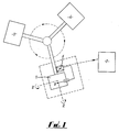
- the rotational moulding apparatus comprises a rotatable mould 1, means 2 for rotating the mould about two perpendicular axes, an oven 3 for heating the mould and an air or water spray 4 for cooling the mould down.
- a device 5 is disposed inside the mould 1 for measuring the temperature inside the mould and a procesor 6 is connected to that device 5 for processing the temperature monitored.
- This processor forms part of a feedback loop which enables the moulding process to be controlled in real time in dependence upon the temperature monitored by means of a control system 7.
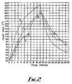
- lines X, Y and Z represent variations of temperature with time for the outside surface of mould 1, the inside surface of the mould 1 and the air within the mould 1 respectively. Temperatures for line Z are measured by device 5.Temperatures for lines X and Y are provided for comparison. Line Z exhibits a sharp kink (pt. A). This indicates the time at which the powder has all melted. At point B the optimum part properties have been achieved. Shorter or longer heating times will result in significantly reduced properties. Point C indicates the point at which the belt has solidified.
- Point A is independent of any of the variables mentioned in the introduction above and is purely a function of the heat transfer conditions. Optimum mechanical properties of the moulded article co-incide with a precise temperature of the air inside the mould represented by point B. These points are unique. Point A is determined because it is located at a discontinuity of line Z. Point B is determined by testing the moulded article against temperature for various materials and various temperatures above the fusion temperature of all the material represented by point A. Point C indicates the time which must elapse before de-moulding can take place.
- the processor 6 may emit a signal when either or both of the temperatures at points A and B are reached.
- the signal emitted is received by the control system 7 which controls the moulding process in dependence upon the signal received as indicated earlier.
- the signal may be transmitted at any appropriate frequency, for example, at a radio frequency or at an infra-red frequency.
- the moulding process may be manually controlled by an operative in dependence upon the temperature monitored.
- the temperature externally of the mould may also be measured and that measurement fed to the processor for conversion to a signal to be transmitted to the control system. This in turn may be used to monitor the heating efficiency of the mould.
- the processor may, in an alternative to the signal emission arrangement, be connected to the control system via slip rings.
Landscapes
- Engineering & Computer Science (AREA)
- Mechanical Engineering (AREA)
- Moulding By Coating Moulds (AREA)
- Moulds For Moulding Plastics Or The Like (AREA)
- Casting Or Compression Moulding Of Plastics Or The Like (AREA)
- Injection Moulding Of Plastics Or The Like (AREA)
Abstract
Description
- The present invention relates to apparatus for and a method of rotational moulding.
- Rotational moulding is a processing method for producing hollow articles made of synthetic plastics material. It consists of three basic stages. Initially, cold plastics powder (or granules) is placed in a sheet metal (or cast alloy) mould. The mould is closed and is rotated simultaneously about two perpendicular axes. Whilst rotating the mould moves into an oven and as the metal surface becomes hot, the plastic in the mould starts to melt and coat the inside surface of the mould. When all the plastics powder has melted and a uniform coating has formed on the mould, it is taken out of the oven and, still rotating, it is cooled by an air and/or water spray. When the plastics has solidified the mould is opened and the moulding is removed.
- The rotational moulding technique has been used commercially for about 30 years but there are a number of practical problems. Firstly, it is very difficult to know when the powder has melted. This is usually estabished by trial and error and results in a considerable amount of wasted material. This is because the heat transfer characteristics can vary depending on the type of oven used to heat the mould, the ambient conditions, the nature of the powder, the type of plastics, the wall thickness of the moulding, the material and thickness of the mould etc. Also, even when the powder has melted it is difficult to know how long the mould should be left in the oven to get optimum properties from the moulded article.
- An existing arrangement in which an attempt has been made to overcome these disadvantages is that described in FR-A-2121741 (document D1). In that specification elements are described for measuring the temperature of the mould and of the material being moulded in the mould, but this method of measuring does not overcome all the above mentioned disadvantages.
- According to one aspect of the present invention, there is provided a rotational moulding apparatus comprising a mould, means for rotating the mould and means for measuring the temperature of the medium inside the mould but outside the material being moulded in order to provide a means for controlling the moulding process.
- According to another aspect of the present invention, there is provided a method of rotational moulding comprising the steps of introducing moulding materials into the mould, heating and rotating the mould and monitoring the temperature of the medium inside the mould but outside the material being moulded and controlling the operation of the moulding machine in dependence upon the temperature monitored.
- In a preferred embodiment, variation of temperature with time is plotted and three unique points on that plot are determined respectively representing when all the plastics material is melted, when the moulded article has achieved its optimum properties and when demoulding can take place. The first point is located at and identified by means of a discontinuity in the heating up part of the temperature time characteristic. The second point is determined by testing the properties of moulded articles at temperatures above the fusion temperatures for different moulding materials. In this way, the second point on the characteristic at which these properties are achieved can be accurately predicted, and by monitoring the temperature, articles having these properties can be produced. The third point is located at and identified by means of a discontinuity in the cooling down part of the temperature - time characteristic.
- Temperature is monitored inside the mould by any appropriate temperature monitoring device. The device can be connected to a processor which can in turn be used to control the moulding process. If desired, the device may emit a continuous signal so that an instant temperature readout is obtained. Alternatively, a data logger for logging the temperature may be used in place of the monitoring device and processor, but this would not provide an instantaneous read out.
- In order that the invention may be more clearly understood, one embodiment thereof will now be described, by way of example, with reference to the accompanying drawings, in which:-
- Figure 1 shows a diagrammatic view of rotational moulding apparatus according to the invention, and
- Figure 2 is a graph of the variation of temperature with time inside the mould of the apparatus of Figure 1.
- Referring to Figure 1, the rotational moulding apparatus comprises a rotatable mould 1, means 2 for rotating the mould about two perpendicular axes, an
oven 3 for heating the mould and an air orwater spray 4 for cooling the mould down. Adevice 5 is disposed inside the mould 1 for measuring the temperature inside the mould and aprocesor 6 is connected to thatdevice 5 for processing the temperature monitored. This processor forms part of a feedback loop which enables the moulding process to be controlled in real time in dependence upon the temperature monitored by means of acontrol system 7. - Referring to Figure 2 lines X, Y and Z represent variations of temperature with time for the outside surface of mould 1, the inside surface of the mould 1 and the air within the mould 1 respectively. Temperatures for line Z are measured by device 5.Temperatures for lines X and Y are provided for comparison. Line Z exhibits a sharp kink (pt. A). This indicates the time at which the powder has all melted. At point B the optimum part properties have been achieved. Shorter or longer heating times will result in significantly reduced properties. Point C indicates the point at which the belt has solidified.
- Point A is independent of any of the variables mentioned in the introduction above and is purely a function of the heat transfer conditions. Optimum mechanical properties of the moulded article co-incide with a precise temperature of the air inside the mould represented by point B. These points are unique. Point A is determined because it is located at a discontinuity of line Z. Point B is determined by testing the moulded article against temperature for various materials and various temperatures above the fusion temperature of all the material represented by point A. Point C indicates the time which must elapse before de-moulding can take place.
- Thus measurement of the air inside the mould enables a moulder to (a) identify the point at which the powder (or granules) has all melted (b) identify the condition at which optimum part properties are achieved and (c) control the operation of the machine in order to optimise the properties of the mouldings. The
processor 6 may emit a signal when either or both of the temperatures at points A and B are reached. The signal emitted is received by thecontrol system 7 which controls the moulding process in dependence upon the signal received as indicated earlier. The signal may be transmitted at any appropriate frequency, for example, at a radio frequency or at an infra-red frequency. - It will be appreciated that the above embodiment has been described by way of example only and that many variations are possible without departing from the invention. For example, instead of automatic control by means of an automatic control system, the moulding process may be manually controlled by an operative in dependence upon the temperature monitored. The temperature externally of the mould may also be measured and that measurement fed to the processor for conversion to a signal to be transmitted to the control system. This in turn may be used to monitor the heating efficiency of the mould. Also the processor may, in an alternative to the signal emission arrangement, be connected to the control system via slip rings.
Claims (12)
- A rotational moulding apparatus comprising a mould, means for rotating the mould and means far measuring the temperature of the medium inside the mould but outside the material being moulded in order to provide a means for controlling the moulding process.
- A rotational moulding apparatus as claimed in claim 1, in which the means for measuring temperature comprises a temperature monitoring device connected to a processor.
- A rotational moulding apparatus as claimed in claim 2, in which the processor is disposed in a feedback loop to control the moulding process.
- A rotational moulding apparatus as claimed in claim 3, in which the processor is operative to emit a continuous signal so that an instant temperature readout may be obtained.
- A rotational moulding apparatus as claimed in claim 4, in which the continuous signal is received in real time by a control system disposed in the feedback loop.
- A rotational moulding apparatus as claimed in claim 4 or 5, in which the signal is an infra-red signal.
- A rotational moulding apparatus as claimed in claim 4 or 5 in which the signal is a radio signal.
- A rotational moulding apparatus as claimed in claim 1, in which the means for measuring temperature comprises a data logger for logging the temperature.
- A method of rotational moulding comprising the steps of introducing moulding materials into the mould, heating and rotating the mould and monitoring the temperature of the medium inside the mould but outside the material being moulded and controlling the operation of the moulding machine in dependence upon the temperature monitored.
- A method of rotational moulding as claimed in claim 9, in which a signal is produced from the monitored temperature and transmitted continuously to a control system which is operative to control the moulding process in dependence upon the signal received.
- A method of rotational moulding as claimed in claim 10, in which the signal is a radio signal.
- A method of rotational moulding as claimed in claim 10, in which the signal is an infra-red signal.
Applications Claiming Priority (3)
| Application Number | Priority Date | Filing Date | Title |
|---|---|---|---|
| GB898923207A GB8923207D0 (en) | 1989-10-14 | 1989-10-14 | Rotational moulding apparatus and process |
| GB8923207 | 1989-10-14 | ||
| PCT/GB1990/001569 WO1991005647A1 (en) | 1989-10-14 | 1990-10-11 | Rotational moulding apparatus and process |
Publications (2)
| Publication Number | Publication Date |
|---|---|
| EP0495829A1 EP0495829A1 (en) | 1992-07-29 |
| EP0495829B1 true EP0495829B1 (en) | 1996-03-20 |
Family
ID=10664610
Family Applications (1)
| Application Number | Title | Priority Date | Filing Date |
|---|---|---|---|
| EP90914945A Expired - Lifetime EP0495829B1 (en) | 1989-10-14 | 1990-10-11 | Rotational moulding apparatus and process |
Country Status (7)
| Country | Link |
|---|---|
| US (1) | US5322654A (en) |
| EP (1) | EP0495829B1 (en) |
| AU (1) | AU6526490A (en) |
| CA (1) | CA2067174C (en) |
| DE (1) | DE69026103T2 (en) |
| GB (1) | GB8923207D0 (en) |
| WO (1) | WO1991005647A1 (en) |
Families Citing this family (15)
| Publication number | Priority date | Publication date | Assignee | Title |
|---|---|---|---|---|
| DE69305996D1 (en) * | 1993-09-22 | 1996-12-19 | Lin Pac Mouldings | Plastic molding process |
| AUPM399094A0 (en) * | 1994-02-18 | 1994-03-17 | Automated Plastic Systems Pty Ltd | Automatic rotamoulding apparatus and method of control |
| GB9421596D0 (en) * | 1994-10-22 | 1994-12-14 | Univ Belfast | A method of and apparatus for rotational moulding |
| FR2736581B1 (en) * | 1995-07-13 | 1997-08-22 | Gallet Jean Yves | ROTOMOLDING PROCESS AND MACHINE FOR CARRYING OUT SAID METHOD |
| GB2311482A (en) * | 1996-03-28 | 1997-10-01 | Matrix Polymers Ltd | Measuring temperature in rotational moulding apparatus |
| US6036897A (en) * | 1997-03-21 | 2000-03-14 | Remcon Plastics, Inc. | Rotational molding apparatus and method using infrared thermometry |
| US6589470B2 (en) * | 1999-04-26 | 2003-07-08 | Robert P. Fried | Process for producing molded plastic articles |
| US6685458B2 (en) | 2001-10-11 | 2004-02-03 | Acushnet Company | Split metal die assembly with injection cycle monitor |
| WO2006090251A1 (en) * | 2005-02-24 | 2006-08-31 | Gary Lategan | Measuring conditions in a rotational moulding process |
| ITMI20051151A1 (en) * | 2005-06-20 | 2006-12-21 | Polivinil Rotomachinery S P A | "MOLD HOLDER ARM FOR ROTATIONAL MOLDING MACHINE WITH TEMPERATURE DETECTION SYSTEM" |
| BE1020382A5 (en) | 2012-04-30 | 2013-08-06 | Plastigi | DEVICE AND METHOD FOR ROTATION CASTING OF PLASTIC. |
| DE102012217763A1 (en) | 2012-09-28 | 2014-04-03 | Institut für Polymertechnologien e.V. | Measuring arrangement for rotary molding machine for manufacturing shaped body of material in rotating mold, is arranged for determination of rotational position of mold and for transmitting measurement signal to data processing device |
| CN103042645B (en) * | 2013-01-24 | 2014-12-10 | 重庆理工大学 | Temperature regulating device for rotational forming die |
| EP4246361B1 (en) * | 2018-11-22 | 2025-01-22 | AMS Belgium | System and method for controlling a rotational moulding process |
| BE1031051B1 (en) | 2022-11-21 | 2024-06-17 | Ams Belgium | System for forming products with an electrically heated mold, including measuring device for current measurement and method |
Family Cites Families (18)
| Publication number | Priority date | Publication date | Assignee | Title |
|---|---|---|---|---|
| DE2101675A1 (en) * | 1971-01-15 | 1972-07-20 | Vox A | Rotary casting machine for the production of plastic moldings |
| DE2261922A1 (en) * | 1972-12-18 | 1974-07-11 | Elkamet Werk | Temp. control of rotationally moulded hollow articles - using recycling line with programme controlled mixer servocontrolled to temp. in heating fluid line |
| US4217325A (en) * | 1977-04-21 | 1980-08-12 | Mccord Corporation | Method using modular slush molding machine |
| US4235577A (en) * | 1979-06-18 | 1980-11-25 | Control Process, Incorporated | Automatic curing cycle control system |
| JPS5816839A (en) * | 1981-07-24 | 1983-01-31 | Sumitomo Rubber Ind Ltd | Method of vulcanizing elastomer product |
| US4455268A (en) * | 1981-07-09 | 1984-06-19 | Applied Polymer Technology, Inc. | Control system for processing composite materials |
| EP0071988B1 (en) * | 1981-08-05 | 1988-05-11 | Sumitomo Rubber Industries Limited | Apparatus for automatically measuring and controlling chemical reaction amount |
| US4371483A (en) * | 1982-01-11 | 1983-02-01 | The B. F. Goodrich Company | Apparatus and process for vulcanizing, adjusted for variable location of point of least cure |
| GB2136114B (en) * | 1983-03-05 | 1986-05-14 | Emhart Ind | Controlling the temperature of a mould |
| US4933126A (en) * | 1984-08-03 | 1990-06-12 | Shuman Jack N | Method and apparatus of temperature control in heat forming of thermoplastic sheet material |
| DE3502006A1 (en) * | 1985-01-23 | 1986-07-24 | Hahn, Ortwin, Prof. Dr.-Ing., 4790 Paderborn | METHOD FOR FOAMING AND SINTERING PLASTICS |
| DE3541258C1 (en) * | 1985-11-22 | 1987-01-15 | Hahn Ortwin | Adaptive control process for foaming and sintering plastic |
| US4740337A (en) * | 1986-05-27 | 1988-04-26 | Sheller-Globe Corporation | Powder slush process for making plastic articles |
| JPS62288025A (en) * | 1986-06-06 | 1987-12-14 | Hitachi Cable Ltd | Control of extruding temprature in synthetic resin extrusion molder |
| US5055245A (en) * | 1986-07-07 | 1991-10-08 | Bridgestone Corporation | Method of measuring temperature within cured article and method of controlling tire vulcanization |
| US4810438A (en) * | 1987-04-30 | 1989-03-07 | The United States Of America As Represented By The United States National Aeronautics And Space Administration | Method of controlling a resin curing process |
| EP0355771B1 (en) * | 1988-08-22 | 1992-11-11 | Freund Industrial Co., Ltd. | Granulating and coating apparatus |
| EP0462062B1 (en) * | 1990-06-13 | 1994-11-09 | Ciba-Geigy Ag | Method of testing the gelling process following casting of a reactive resin in a production mould |
-
1989
- 1989-10-14 GB GB898923207A patent/GB8923207D0/en active Pending
-
1990
- 1990-10-11 DE DE69026103T patent/DE69026103T2/en not_active Expired - Fee Related
- 1990-10-11 WO PCT/GB1990/001569 patent/WO1991005647A1/en not_active Ceased
- 1990-10-11 CA CA002067174A patent/CA2067174C/en not_active Expired - Lifetime
- 1990-10-11 US US07/847,105 patent/US5322654A/en not_active Expired - Lifetime
- 1990-10-11 EP EP90914945A patent/EP0495829B1/en not_active Expired - Lifetime
- 1990-10-11 AU AU65264/90A patent/AU6526490A/en not_active Abandoned
Also Published As
| Publication number | Publication date |
|---|---|
| WO1991005647A1 (en) | 1991-05-02 |
| EP0495829A1 (en) | 1992-07-29 |
| CA2067174C (en) | 1998-06-30 |
| DE69026103D1 (en) | 1996-04-25 |
| DE69026103T2 (en) | 1996-10-31 |
| GB8923207D0 (en) | 1989-11-29 |
| US5322654A (en) | 1994-06-21 |
| CA2067174A1 (en) | 1991-04-15 |
| AU6526490A (en) | 1991-05-16 |
Similar Documents
| Publication | Publication Date | Title |
|---|---|---|
| US5322654A (en) | Rotational moulding apparatus and process | |
| US5868979A (en) | Automatic rotamoulding apparatus and method of control | |
| EP1019231B1 (en) | Rotational molding apparatus using infrared thermometry feedback | |
| JPS6149095B2 (en) | ||
| US4979888A (en) | Apparatus for molding an article from a fusible synthetic resin | |
| JP2007521986A (en) | Method and apparatus for measuring and controlling both the inner and outer surface temperatures of a thermoplastic preform during a stretch blow molding operation | |
| Crawford | Recent advances in the manufacture of plastic products by rotomoulding | |
| IL58549A (en) | Method and apparatus for producing molded plastic articles | |
| CA1227308A (en) | Process and apparatus for vulcanising / pneumatic tires / | |
| Spalding et al. | Coefficients of dynamic friction for low density polyethylene | |
| US4957671A (en) | Manufacture of plastic products | |
| US4877564A (en) | Method and apparatus for measuring and controlling blow-up of a foam sheet in a thermoformer oven | |
| JP2563224B2 (en) | Extrusion molding control method | |
| WO1998041377A1 (en) | Continuous mold temperature monitoring system and method for rotational mold | |
| GB2311482A (en) | Measuring temperature in rotational moulding apparatus | |
| JPS56162624A (en) | Method and device for plastic molding | |
| Liu et al. | Significance of processing parameters on the warpage of rotationally molded parts | |
| DiScipio et al. | Verification Mold for Flow, Cooling, Shrinkage and Warpage Analysis | |
| JP2589395Y2 (en) | Mold heating device of slush molding machine | |
| JPH05146844A (en) | Method for controlling temperature of shell molding machine | |
| JPS6149094B2 (en) | ||
| Dormeier | Programmable Digital Temperature Controller. Control Studies on a 50 mm Extruder | |
| Bigg | An investigation of the shrinkage behavior of oriented PVC in a hot air tunnel | |
| KR940002028A (en) | Molding apparatus for forming composite materials | |
| JPS59167242A (en) | Controlling method of temperature of resin in plastic molding machine |
Legal Events
| Date | Code | Title | Description |
|---|---|---|---|
| PUAI | Public reference made under article 153(3) epc to a published international application that has entered the european phase |
Free format text: ORIGINAL CODE: 0009012 |
|
| 17P | Request for examination filed |
Effective date: 19920501 |
|
| AK | Designated contracting states |
Kind code of ref document: A1 Designated state(s): DE DK ES FR GB IT NL SE |
|
| 17Q | First examination report despatched |
Effective date: 19940223 |
|
| GRAH | Despatch of communication of intention to grant a patent |
Free format text: ORIGINAL CODE: EPIDOS IGRA |
|
| GRAA | (expected) grant |
Free format text: ORIGINAL CODE: 0009210 |
|
| AK | Designated contracting states |
Kind code of ref document: B1 Designated state(s): DE DK ES FR GB IT NL SE |
|
| PG25 | Lapsed in a contracting state [announced via postgrant information from national office to epo] |
Ref country code: DK Effective date: 19960320 Ref country code: ES Free format text: THE PATENT HAS BEEN ANNULLED BY A DECISION OF A NATIONAL AUTHORITY Effective date: 19960320 Ref country code: NL Free format text: LAPSE BECAUSE OF FAILURE TO SUBMIT A TRANSLATION OF THE DESCRIPTION OR TO PAY THE FEE WITHIN THE PRESCRIBED TIME-LIMIT Effective date: 19960320 |
|
| REF | Corresponds to: |
Ref document number: 69026103 Country of ref document: DE Date of ref document: 19960425 |
|
| ITF | It: translation for a ep patent filed | ||
| PG25 | Lapsed in a contracting state [announced via postgrant information from national office to epo] |
Ref country code: SE Effective date: 19960620 |
|
| ET | Fr: translation filed | ||
| NLV1 | Nl: lapsed or annulled due to failure to fulfill the requirements of art. 29p and 29m of the patents act | ||
| PLBE | No opposition filed within time limit |
Free format text: ORIGINAL CODE: 0009261 |
|
| STAA | Information on the status of an ep patent application or granted ep patent |
Free format text: STATUS: NO OPPOSITION FILED WITHIN TIME LIMIT |
|
| 26N | No opposition filed | ||
| PGFP | Annual fee paid to national office [announced via postgrant information from national office to epo] |
Ref country code: FR Payment date: 20001031 Year of fee payment: 11 |
|
| PGFP | Annual fee paid to national office [announced via postgrant information from national office to epo] |
Ref country code: DE Payment date: 20001215 Year of fee payment: 11 |
|
| REG | Reference to a national code |
Ref country code: GB Ref legal event code: IF02 |
|
| PG25 | Lapsed in a contracting state [announced via postgrant information from national office to epo] |
Ref country code: FR Free format text: LAPSE BECAUSE OF NON-PAYMENT OF DUE FEES Effective date: 20020628 |
|
| PG25 | Lapsed in a contracting state [announced via postgrant information from national office to epo] |
Ref country code: DE Free format text: LAPSE BECAUSE OF NON-PAYMENT OF DUE FEES Effective date: 20020702 |
|
| REG | Reference to a national code |
Ref country code: FR Ref legal event code: ST |
|
| PG25 | Lapsed in a contracting state [announced via postgrant information from national office to epo] |
Ref country code: IT Free format text: LAPSE BECAUSE OF NON-PAYMENT OF DUE FEES;WARNING: LAPSES OF ITALIAN PATENTS WITH EFFECTIVE DATE BEFORE 2007 MAY HAVE OCCURRED AT ANY TIME BEFORE 2007. THE CORRECT EFFECTIVE DATE MAY BE DIFFERENT FROM THE ONE RECORDED. Effective date: 20051011 |
|
| PGFP | Annual fee paid to national office [announced via postgrant information from national office to epo] |
Ref country code: GB Payment date: 20090430 Year of fee payment: 19 |
|
| PG25 | Lapsed in a contracting state [announced via postgrant information from national office to epo] |
Ref country code: GB Free format text: LAPSE BECAUSE OF NON-PAYMENT OF DUE FEES Effective date: 20091011 |