EP0494700A2 - Bilderzeugendes LIDAR-System für flache und Küsten-Gewässer - Google Patents
Bilderzeugendes LIDAR-System für flache und Küsten-Gewässer Download PDFInfo
- Publication number
- EP0494700A2 EP0494700A2 EP92105505A EP92105505A EP0494700A2 EP 0494700 A2 EP0494700 A2 EP 0494700A2 EP 92105505 A EP92105505 A EP 92105505A EP 92105505 A EP92105505 A EP 92105505A EP 0494700 A2 EP0494700 A2 EP 0494700A2
- Authority
- EP
- European Patent Office
- Prior art keywords
- peaks
- likelihood function
- pulses
- light
- composite
- Prior art date
- Legal status (The legal status is an assumption and is not a legal conclusion. Google has not performed a legal analysis and makes no representation as to the accuracy of the status listed.)
- Granted
Links
- 238000003384 imaging method Methods 0.000 title claims abstract description 47
- 239000003653 coastal water Substances 0.000 title abstract description 4
- 230000006870 function Effects 0.000 claims description 103
- 239000002131 composite material Substances 0.000 claims description 46
- XLYOFNOQVPJJNP-UHFFFAOYSA-N water Substances O XLYOFNOQVPJJNP-UHFFFAOYSA-N 0.000 claims description 39
- 238000000034 method Methods 0.000 claims description 29
- 230000003287 optical effect Effects 0.000 claims description 12
- 238000012545 processing Methods 0.000 claims description 9
- 238000013138 pruning Methods 0.000 claims description 7
- 230000000717 retained effect Effects 0.000 claims description 6
- 230000004044 response Effects 0.000 claims description 5
- 238000012544 monitoring process Methods 0.000 claims description 3
- 238000004891 communication Methods 0.000 claims 4
- 230000001131 transforming effect Effects 0.000 claims 4
- 238000001514 detection method Methods 0.000 abstract description 35
- 230000004807 localization Effects 0.000 abstract description 6
- 238000011897 real-time detection Methods 0.000 abstract description 5
- 238000001816 cooling Methods 0.000 description 6
- 238000005286 illumination Methods 0.000 description 5
- 238000004364 calculation method Methods 0.000 description 4
- 238000010586 diagram Methods 0.000 description 4
- 230000000694 effects Effects 0.000 description 4
- 239000006260 foam Substances 0.000 description 4
- 230000010354 integration Effects 0.000 description 3
- 239000013535 sea water Substances 0.000 description 3
- 230000000007 visual effect Effects 0.000 description 3
- 238000004458 analytical method Methods 0.000 description 2
- 230000003466 anti-cipated effect Effects 0.000 description 2
- 230000005540 biological transmission Effects 0.000 description 2
- 238000010276 construction Methods 0.000 description 2
- 230000002596 correlated effect Effects 0.000 description 2
- 230000004927 fusion Effects 0.000 description 2
- 230000006872 improvement Effects 0.000 description 2
- 238000012986 modification Methods 0.000 description 2
- 230000004048 modification Effects 0.000 description 2
- 230000008569 process Effects 0.000 description 2
- 230000009467 reduction Effects 0.000 description 2
- 239000004576 sand Substances 0.000 description 2
- 239000007921 spray Substances 0.000 description 2
- 241000193901 Dreissena polymorpha Species 0.000 description 1
- 230000006978 adaptation Effects 0.000 description 1
- 230000003321 amplification Effects 0.000 description 1
- 238000013459 approach Methods 0.000 description 1
- 238000003491 array Methods 0.000 description 1
- 230000003750 conditioning effect Effects 0.000 description 1
- 238000012790 confirmation Methods 0.000 description 1
- 239000002826 coolant Substances 0.000 description 1
- 238000013479 data entry Methods 0.000 description 1
- 238000000354 decomposition reaction Methods 0.000 description 1
- 230000007423 decrease Effects 0.000 description 1
- 230000007812 deficiency Effects 0.000 description 1
- 230000001934 delay Effects 0.000 description 1
- 230000000881 depressing effect Effects 0.000 description 1
- 239000000428 dust Substances 0.000 description 1
- 238000002592 echocardiography Methods 0.000 description 1
- 238000005516 engineering process Methods 0.000 description 1
- 230000007613 environmental effect Effects 0.000 description 1
- 239000002360 explosive Substances 0.000 description 1
- 230000002349 favourable effect Effects 0.000 description 1
- 238000001914 filtration Methods 0.000 description 1
- 239000003897 fog Substances 0.000 description 1
- 238000010348 incorporation Methods 0.000 description 1
- 230000000116 mitigating effect Effects 0.000 description 1
- 239000000203 mixture Substances 0.000 description 1
- 230000004297 night vision Effects 0.000 description 1
- 238000010606 normalization Methods 0.000 description 1
- 238000003199 nucleic acid amplification method Methods 0.000 description 1
- 238000004806 packaging method and process Methods 0.000 description 1
- 230000035515 penetration Effects 0.000 description 1
- 239000013049 sediment Substances 0.000 description 1
- 238000011896 sensitive detection Methods 0.000 description 1
- 230000035945 sensitivity Effects 0.000 description 1
- 239000000779 smoke Substances 0.000 description 1
- 238000006467 substitution reaction Methods 0.000 description 1
- 230000001960 triggered effect Effects 0.000 description 1
- 239000003643 water by type Substances 0.000 description 1
Images


Classifications
-
- G—PHYSICS
- G01—MEASURING; TESTING
- G01S—RADIO DIRECTION-FINDING; RADIO NAVIGATION; DETERMINING DISTANCE OR VELOCITY BY USE OF RADIO WAVES; LOCATING OR PRESENCE-DETECTING BY USE OF THE REFLECTION OR RERADIATION OF RADIO WAVES; ANALOGOUS ARRANGEMENTS USING OTHER WAVES
- G01S7/00—Details of systems according to groups G01S13/00, G01S15/00, G01S17/00
- G01S7/48—Details of systems according to groups G01S13/00, G01S15/00, G01S17/00 of systems according to group G01S17/00
- G01S7/483—Details of pulse systems
- G01S7/486—Receivers
- G01S7/487—Extracting wanted echo signals, e.g. pulse detection
-
- G—PHYSICS
- G01—MEASURING; TESTING
- G01S—RADIO DIRECTION-FINDING; RADIO NAVIGATION; DETERMINING DISTANCE OR VELOCITY BY USE OF RADIO WAVES; LOCATING OR PRESENCE-DETECTING BY USE OF THE REFLECTION OR RERADIATION OF RADIO WAVES; ANALOGOUS ARRANGEMENTS USING OTHER WAVES
- G01S17/00—Systems using the reflection or reradiation of electromagnetic waves other than radio waves, e.g. lidar systems
- G01S17/02—Systems using the reflection of electromagnetic waves other than radio waves
- G01S17/06—Systems determining position data of a target
- G01S17/08—Systems determining position data of a target for measuring distance only
- G01S17/10—Systems determining position data of a target for measuring distance only using transmission of interrupted, pulse-modulated waves
- G01S17/18—Systems determining position data of a target for measuring distance only using transmission of interrupted, pulse-modulated waves wherein range gates are used
-
- G—PHYSICS
- G01—MEASURING; TESTING
- G01S—RADIO DIRECTION-FINDING; RADIO NAVIGATION; DETERMINING DISTANCE OR VELOCITY BY USE OF RADIO WAVES; LOCATING OR PRESENCE-DETECTING BY USE OF THE REFLECTION OR RERADIATION OF RADIO WAVES; ANALOGOUS ARRANGEMENTS USING OTHER WAVES
- G01S17/00—Systems using the reflection or reradiation of electromagnetic waves other than radio waves, e.g. lidar systems
- G01S17/66—Tracking systems using electromagnetic waves other than radio waves
-
- G—PHYSICS
- G01—MEASURING; TESTING
- G01S—RADIO DIRECTION-FINDING; RADIO NAVIGATION; DETERMINING DISTANCE OR VELOCITY BY USE OF RADIO WAVES; LOCATING OR PRESENCE-DETECTING BY USE OF THE REFLECTION OR RERADIATION OF RADIO WAVES; ANALOGOUS ARRANGEMENTS USING OTHER WAVES
- G01S17/00—Systems using the reflection or reradiation of electromagnetic waves other than radio waves, e.g. lidar systems
- G01S17/88—Lidar systems specially adapted for specific applications
- G01S17/89—Lidar systems specially adapted for specific applications for mapping or imaging
Definitions
- This invention relates generally to a sensor system for remote detection and imaging of objects in a backscattering medium such as water. More particularly, this invention relates to a method and apparatus for detecting, locating and/or imaging underwater objects in shallow water and in coastal regions from an airborne platform using a novel imaging lidar (light detection and ranging) system which improves imaging in such shallow water areas.
- a novel imaging lidar light detection and ranging
- wire line devices Presently, cumbersome and time consuming wire line devices must be used for detecting underwater targets from remote airborne locations. These devices are lowered into the water and are easily subject to damage and loss. Also, wire line devices make target searching relatively slow and can only detect targets without providing visual imaging.
- U.S. Patent 4,862,257 and U.S. Patent 5,013,917 both of which are assigned to the assignee hereof and incorporated herein by reference.
- the imaging lidar system of U.S. Patent 4,862,257 utilizes a laser to generate short pulses of light with pulse widths on the order of nanoseconds. The laser light is expanded by optics and projected down toward the surface of the water and to an object or target.
- U.S. Patent 5,013,917 relates to an imaging lidar system intended for night vision.
- Patent 4,964,721 relates to an imaging lidar system which controls camera gating based on input from the aircraft onboard altimeter and uses a computer to thereby adjust total time delay so as to automatically track changing platform altitude.
- Patent 4,967,270 relates to a lidar system employing a plurality of gated cameras which are individually triggered after preselected time delays to obtain multiple subimages laterally across a target image. These multiple subimages are then put together in a mosaic in a computer to provide a complete image of a target plane preferably using only a single light pulse.
- Patent Nos. 5,029,009 and 5,034,810 are disclosed in commonly assigned U.S. Patent Nos. 5,029,009 and 5,034,810, both of which are incorporated herein by reference.
- Patent No. 5,029,009 describes an imaging lidar system incorporating an imaging camera having a plurality of gating electrodes on a focal plane and means for producing variable time delay gating across an image viewed by the focal plane.
- Patent 5,034,810 relates to a two wavelength lidar imaging system for underwater application utilizing image subtraction to detect passage of internal waves or other anomalies under water.
- USSN 565,631 filed August 10, 1990 which is also assigned to the assignee hereof and fully incorporated herein by reference, relates to an airborne imaging lidar system which employs a plurality of pulsed laser transmitters, a plurality of gated and intensified array camera receivers, an optical scanner for increased field of regard, and a computer for system control, automatic target detection and display generation.
- USSN 565,631 provides a means for rapidly searching a large volume of the backscattering medium (e.g., water) for specified targets and improves upon prior art devices in performance as a result of having more energy in each laser pulse (due to simultaneous operation of multiple lasers) and a more sensitive detection system using multiple cameras.
- the backscattering medium e.g., water
- the several cameras may be utilized to image different range gates on a single laser pulse or several cameras can be gated on at the same time to provide independent pictures which can then be averaged to reduce the noise level and improve sensitivity. Both of these improvements result in higher signal-to-noise ratio and thus higher probability of detection or greater range of depth capability.
- Imaging lidar system of the type hereinabove discussed are often used in conjunction with computerized automatic target detection (ATD) systems for detecting, locating and identifying targets from a plurality of two dimensional images. Examples of such ATD systems are described in commonly assigned U.S. Application Serial Nos. 565,425 and 565,424, both of which were filed on August 10, 1990 and are incorporated herein by reference.
- ATD automatic target detection
- the present invention overcomes deficiencies in the prior art by providing an apparatus and method for detecting, classifying and localizing objects in the surf zone and in shallow water.
- This invention thus comprises an airborne imaging lidar system for detection and classification of objects in the surf zone of coastal waters.
- the lidar transmitter is a repetitively pulsed Nd:YAG laser illuminating a portion of the coastal marine area for imaging by a gated camera (e.g., CCD camera) with optimized gating time delay.
- the present invention includes high spatial resolution and target detection algorithms to classify objects and discriminate against clutter. As a result, the present invention is capable of rapid search of coastal areas, performs real time automatic target detection, noise rejection and classification, and is capable of both day and night operations under a wide range of sea state and water clarity.
- Important features of this invention include multiple imaging cameras to provide high spatial resolution, a bottom tracker to maintain camera gating at the optimum local bottom depth, a specialized beam projection system to minimize brightness variations across the field of view and which optimizes the spatial relationship of the transmitted light to the geometry of the receiver optics, and finally, target detection computers to provide real time detection and classification of surf zone obstacles.
- the imaging system of this invention is superior to alternative search systems due to its enhanced capability of high search rate, broad area instead of narrow area illumination, high spatial resolution and real time detection and classification.
- the present invention provides the capability for rapid and reliable search, detection, classification, and localization of objects in the surf zone, which may present hazards to navigation and utilization of coastal areas.
- This invention is capable of rapidly surveying large areas of coastline, providing real time detection and classification, and displaying the results to a human operator to allow for real time assessment of potential hazards in the surf zone.
- This invention is of great interest to both military and commercial application for identification of man-made and natural obstacles and hazards in coastal regions. It will be appreciated that while prior art imaging lidar systems such as described in aforementioned U.S. Patent 4,862,257 and USSN 565,631 are well suited for deeper water detection, the methods and apparatus for the airborne imaging LIDAR systems of this invention optimize the configuration for surf zone surveillance resulting in substantial improvement.
- the elaborate step by step spot illumination associated with certain prior art devices is not needed for following varying underwater contours. Instead, the wide area illumination used in this invention, with gating control based on the bottom echoes is more than adequate for illuminating such varying underwater contours.
- the instrument must have high spatial resolution to a adequately classify obstacles and discriminate against clutter, the sensor must be adaptable to rapidly varying bottom depths and sea surface elevations, and must contend with large variability in sea surface conditions (e.g., breaking waves and foam), and be robust with respect to variable conditions in ambient light and water clarity.
- active illumination e.g., laser
- a gateable camera for discrimination against ambient noise
- automatic gate timing to follow variations in bottom depth
- an imaging array to provide high spatial resolution and a high speed computer for automatic target detection, classification and display.
- FIGURE 1 The sensor block diagram of the present invention is illustrated in FIGURE 1.
- the present invention will be described with respect to a sensor configuration for integration into high speed, fixed wing aircraft.
- the present invention is intended to include numerous packaging variants to allow deployment on a wide variety of both fixed and rotary wing aircraft (both piloted and unmanned), while requiring minimal modification to the host platform.
- the sensor comprises three physical units; an externally mounted pod 10, an equipment rack 12, and a cooling system 22.
- Pod 10 contains the laser transmitter 16, the cameras 18, the scanner 20 and the cooling system 22 which provides the necessary cooling for the laser transmitter through coolant lines 24.
- the laser transmitter 16 characteristics include short pulses for range resolution and daylight noise rejection (less than 20nsec pulse width), wavelength chosen for optimal penetration into seawater (500 to 550nm for coastal water), and pulse energy and PRF chosen to meet detection depth and area coverage requirements, respectively.
- Current technology favors use of a flashlamp as described in U.S. Patent 4,862,257 or diode pumped doubled Neodymium-YAG lasers as described in U.S Patent Application S.N.
- the entire transmitter assembly consists of the laser 16, a beam projector 26 and scanner 20. Cooling is provided within the pod 10 through cooling lines 24 from the cooling system 22.
- the beam projector 26 modifies the spatial cross section of the laser beam 28 to provide the appropriate beam footprint 30 at the water surface 32.
- the scanner 20 steers the output of the beam projector to provide both an adequate swath width and to compensate for aircraft roll variations.
- the receiver assembly comprises the scanner 20, beam collection optics (co-aligned with the transmitter) 34, a narrow band optical filter 36, and camera 18.
- Camera 18 comprises a photocathode optimized for maximum response at the transmitted wavelength, a gateable microchannel plate (MCP) which provides both fast gating and low noise amplification, one or more intermediate gain sections, and a charge coupled device (CCD) to digitize the image outputs as in U.S. Patent 4,862,257.
- MCP gateable microchannel plate
- CCD charge coupled device
- Camera characteristics include the capability of short gating for ambient (sunlight) noise rejection and backscatter noise mitigation (water backscatter); high spatial resolution for target identification, classification, and clutter rejection.
- camera 18 also includes an adequate format to cover the transmitter footprint.
- CCD Complementary Metal-Oxide-Coupled Device
- pod 10 configuration is given only as an example to illustrate the configuration of the present embodiment.
- Other configurations are possible which involve pod placement internal to the aircraft fuselage.
- Receiver field of view is constrained by brightness variation due to slant range variation at non-normal look angles. To maintain adequate contrast resolution across the image and to keep the image levels within the intensity dynamic range of the CCD, the field of view is constrained to limit brightness variations to less than a factor of about four.
- the maximum field of view is constrained by: ⁇ (ncos2 ⁇ /Hsin ⁇ ) (1nB/2ka) where H is the altitude, ⁇ is the incidence angle from the normal, n is the index of refraction of seawater, k a is the attenuation coefficient for the water, and B is the maximum permissible brightness variation.
- this constraint provides an upper limit on the instantaneous field of view (IFOV) along the roll axis direction.
- IFOV instantaneous field of view
- the field of view is determined primarily by speed of advance of the aircraft platform.
- the along track footprint can become quite large, and the sensor field of view is divided between multiple cameras to maintain a modest aspect ratio for each individual camera.
- the equipment rack 12 provides system power, system control, and data acquisition/processing functions.
- System power is derived from primary aircraft power 40 through conditioning equipment 42 contained in the rack.
- An instrument control computer 44 provides command, control and timing functions for the overall system.
- Computer 44 also uses aircraft navigation and attitude information 46 to provide precise localization information for the detected obstacles. This can take the form of GPS inputs, loran or a target detection computer input based on navigational aids, or celestial fixes.
- a target detection computer 48 receives incoming raw sensor data (digital) through transmission line 50, and performs the appropriate normalization and filtering functions, identifies probable targets by comparison with a preset threshold, and alerts the operator at a visual display monitor 52 through line 54 with a highlighted video message and an enhanced display of the suspected target.
- a data recorder 56 is included to provide data archives for post-mission analysis.
- the video data from the camera(s) 18 are transmitted through line 50 to the target data computer 48 for analysis, but is subsequently transmitted through line 58 to the data recorder 56, as well as to the visual display monitor 52 for real time viewing.
- the present invention has the capability of recalling data from the data recorder 56 for replay. If required, the data can be transmitted for real time remote viewing by the data link 60 and its transmitter antenna 62 to another location on shore or off shore (for example, ship 64).
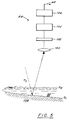
- bottom tracker 66 comprises input optics 100 (e.g., suitable lens), a narrow bandpass optical filter 102 matched to the laser wavelength, a photomultiplier tube or avalanche photodiode 104 and a preamplifier/discriminator 106 for detecting the bottom reflection. As shown in FIGURE 5, bottom tracker 66 determines the varying range between tracker 66 and the bottom 108.
- the scanner 20 comprises an elongated mirror which can scan the transmitted beam and receiver fields of view along a common axis as described in USSN 565,631. By scanning the optical axis in the roll direction, both a larger swath width and roll compensation are achieved.
- the sensor station 72 is the aircrew interface for system control and monitoring. It includes high level control of system operation, presents status information to the operator, and presents enhanced target images for operator confirmation.
- the operator controls the entire mission through the mission control panel 76. This part of the sensor station involves only the laser transmitter on-off and standby switches.
- the data entry device 78 is used to set the various operating parameters to be used during the operation and are provided as input to the instrument control computer 44 through the transmission line 74.
- FIGURE 2 an example of a novel scan pattern for a high resolution, high speed surveillance system is shown.
- six cameras 18 are utilized to cover the highly elongated footprint of the transmitter.
- a larger or smaller number of cameras can be used, limited only by cost or practical considerations.
- the six camera configuration is chosen only as an example.
- this novel division of the sensor field of view among multiple cameras avoids difficulties associated with viewing large aspect ratio areas with a single camera.
- the aspect ratio for an individual camera is 2:1, which is readily accommodated with commercially available CCD hardware.
- the high degree of overlap between cameras, laser shots, and scan lines provides for precise image to image intercalibration and registration, and allows for large scale scene reconstruction.
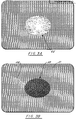
- FIGURE 3A shows a buoyant opaque object 45 suspended in a Scripps Ocean Tank. It is in 30 feet of sea water, suspended 15 feet from the tank bottom. It is spherical in shape, as can be seen from the intensity pattern which peaks in the object's center and decreases to the outer boundary of the image.
- the camera is gated to eliminate surface glint and reflections from the bottom.
- FIGURE 3B shows the bottom of the Scripps Ocean Tank.
- the gate was chosen to illuminate the water below the suspended opaque object, and the tank bottom.
- the object is now seen in obscuration, or a shadow 50 cast by the object in the field of upward-welling illuminating light.
- the bottom is intensely illuminated over the region 51, and a small tether cord 52 can actually be seen on the bottom, again illustrating the ability of this embodiment to identify underwater objects in coastal or lattoral regions.
- FIGURE 4 automatic detection, localization, and classification will be performed on a separate target detection computer 10 previously shown in FIGURE 1.
- the amount of data in an imaging LIDAR system depends upon the selected search volume and for large volumes, the amount of data is immense. Accordingly, processing the data presents a daunting problem, both in terms of memory capacity and processor speed since real time detections are required.
- Single frame processing limits the memory requirement to one frame of data, but at the loss of signal-to-noise ratio that could be achieved through interframe correlation.
- the target detection algorithm presented herein addresses that problem by performing a novel data reduction step to minimize the load on both the memory and the processor.
- the algorithm achieves this reduction by retaining only information about each frame which is important for target detections. Sufficient statistical information is retained to perform a Bayesian update when part of the search area is revisited during the search. By fusing the available information from scan to scan, signal-to-noise ratio, and, therefore, the potential for target detection, is increased.
- the data is obtained over time as a sequence of two dimensional arrays of numbers.
- the data is assumed to follow a multivariate Gaussian distribution with known covariance structure.
- the target signature is also assumed known, and will depend upon the position of the frame with respect to the target.
- the likelihood calculations are best done in transform coordinates.
- the data, the target signature, and the covariance structure of the noise field are transformed using a discrete Fourier transform.
- the logarithm of the multiple frame likelihood function splits into two terms, one, called the matched filter (MF), which depends on the data, and another, called the signal-to-noise ratio (SNR), which depends upon the target signature relative to the noise model and the number of scans that we have on the particular area.
- MF matched filter
- SNR signal-to-noise ratio
- each of these single-frame likelihood functions is of a particular form. Away from the areas of signal energy, the likelihood is nearly zero, and in the proximity of a target-like object, the likelihood function will be peaked.
- we apply the following procedure We select a fixed number of peaks in the likelihood function, and then store their location, their height above the surrounding flat area (e.g., base level), and some information about their spread.
- each peak we represent each peak as a two-dimensional Gaussian function, and the base level by a slowly varying function in a convenient parametric form (see FIGURE 4).
- Each single-frame likelihood function is represented in such a form.
- the kth composite multiple frame likelihood function is a fusion of the first k single frame likelihood function, and represents a summary of all of the data in the first k frames.
- Each of the composite multiple frame likelihood functions is in the same form as the single frame likelihood functions, namely a base level plus a number of Gaussian peaks.
- the k + 1 composite multiple frame likelihood function can be computed from the kth composite multiple frame likelihood function and k + 1 single frame likelihood function by a elegantly simple process due to the novel representation of all the likelihood functions (e.g., FIGURE 4). This is an important and significant feature of the present invention.
- each is represented in terms of a sum of base level and a number of Gaussian peaks
- the fusion of these two likelihoods is again the sum of a base level and a number of Gaussian peaks.
- the new peaks of the new composite multiple frame likelihood function are of three types (e.g., Updated, New and Continued, see Tables 1 and 2).
- the parameters - location, height, spread - of the new peaks are computable in terms of the parameters of the single-frame peaks. This calculation is described in detail hereinafter.
- the number of new peaks will be (N+1)(M+1)-1 if the number of peaks in the single-frame likelihood function and the composite multiple frame likelihood function being fused are N and M, respectively.
- N and M the number of peaks in the single-frame likelihood function and the composite multiple frame likelihood function being fused.
- the peaks are chosen depending upon the height parameter of the new peak.
- the number M can be chosen to be appropriate to the processing power and capacity of the computer being used. Tables 1 and 2 provide a clear picture of the necessary computations for fusing and pruning.
- This fusing and pruning procedure is repeated until all of the data frames have been processed and the multiple frame likelihood function has been determined. Detections are called after a fixed sub volume of the search volume has has been prosecuted and no further data from the sub volume is obtained. If the multiple frame likelihood function at any location in the sub volume exceeds a threshold, a target detection is made. This process is especially well suited for long search missions where areas are not revisited during the mission.
- H t (a,b,d) incorporates the SNR term as well as smoothly varying unmodeled effects.
- this product may be written in the form: n(x
- u1, ⁇ 1 + ⁇ 2), where 1. ⁇ * [ ⁇ 1-1 + ⁇ 2-1]-1, and
- Table 1 provides a graphic method for calculating expression (3).
- Table 2 provides the method for recursive computation of the (k+1) st likelihood function from the k th .
Landscapes
- Physics & Mathematics (AREA)
- Engineering & Computer Science (AREA)
- Electromagnetism (AREA)
- Computer Networks & Wireless Communication (AREA)
- General Physics & Mathematics (AREA)
- Radar, Positioning & Navigation (AREA)
- Remote Sensing (AREA)
- Optical Radar Systems And Details Thereof (AREA)
- Radar Systems Or Details Thereof (AREA)
Applications Claiming Priority (2)
| Application Number | Priority Date | Filing Date | Title |
|---|---|---|---|
| US07/774,663 US5457639A (en) | 1991-10-11 | 1991-10-11 | Imaging lidar system for shallow and coastal water |
| US774663 | 1991-10-11 |
Publications (3)
| Publication Number | Publication Date |
|---|---|
| EP0494700A2 true EP0494700A2 (de) | 1992-07-15 |
| EP0494700A3 EP0494700A3 (en) | 1993-03-03 |
| EP0494700B1 EP0494700B1 (de) | 1997-03-05 |
Family
ID=25101880
Family Applications (1)
| Application Number | Title | Priority Date | Filing Date |
|---|---|---|---|
| EP92105505A Expired - Lifetime EP0494700B1 (de) | 1991-10-11 | 1992-03-31 | Bilderzeugendes LIDAR-System für flache und Küsten-Gewässer |
Country Status (4)
| Country | Link |
|---|---|
| US (1) | US5457639A (de) |
| EP (1) | EP0494700B1 (de) |
| AT (1) | ATE149693T1 (de) |
| DE (1) | DE69217678D1 (de) |
Cited By (8)
| Publication number | Priority date | Publication date | Assignee | Title |
|---|---|---|---|---|
| EP0631154A1 (de) * | 1993-06-21 | 1994-12-28 | DORNIER GmbH | Intelligente Entfernungsbildkamera zur Objektvermessung |
| EP0698550A1 (de) * | 1994-08-23 | 1996-02-28 | Hughes Aircraft Company | Zerstörung von Unterwasser-Gegenständen |
| US8896695B2 (en) | 2002-08-28 | 2014-11-25 | Visual Intelligence Lp | Retinal concave array compound camera system |
| US8994822B2 (en) | 2002-08-28 | 2015-03-31 | Visual Intelligence Lp | Infrastructure mapping system and method |
| US9389298B2 (en) | 2002-09-20 | 2016-07-12 | Visual Intelligence Lp | Self-calibrated, remote imaging and data processing system |
| EP3385752A1 (de) * | 2017-04-06 | 2018-10-10 | Valeo Schalter und Sensoren GmbH | Verbesserte auflösung für ein lidar-sensorsystem für ein kraftfahrzeug |
| CN110673112A (zh) * | 2019-12-05 | 2020-01-10 | 湖南国天电子科技有限公司 | 一种条纹管激光雷达距离选通门控制方法及装置 |
| USRE49105E1 (en) | 2002-09-20 | 2022-06-14 | Vi Technologies, Llc | Self-calibrated, remote imaging and data processing system |
Families Citing this family (29)
| Publication number | Priority date | Publication date | Assignee | Title |
|---|---|---|---|---|
| US6963354B1 (en) * | 1997-08-07 | 2005-11-08 | The United States Of America As Represented By The Secretary Of The Navy | High resolution imaging lidar for detecting submerged objects |
| JP3723721B2 (ja) * | 2000-05-09 | 2005-12-07 | ペンタックス株式会社 | 光波測距儀及びaf機能を有する光波測距儀 |
| US6690017B2 (en) | 2002-02-21 | 2004-02-10 | Ford Global Technologies, Llc | GPS-based anti-blinding system for active night vision |
| AU2003304436A1 (en) * | 2002-12-13 | 2005-03-07 | Utah State University Research Foundation | A vehicle mounted system and method for capturing and processing physical data |
| AU2006345002B2 (en) * | 2005-07-27 | 2012-02-02 | L-3 Communications Cyterra Corporation | Energetic material detector |
| US8292496B1 (en) | 2005-07-27 | 2012-10-23 | L-3 Communications Cyterra Corporation | Energetic material detector |
| US20110151575A1 (en) * | 2005-07-27 | 2011-06-23 | L-3 Communications Cyterra Corporation | Energetic Material Detector |
| US7916933B2 (en) * | 2007-01-18 | 2011-03-29 | Northrop Grumman Systems Corporation | Automatic target recognition system for detection and classification of objects in water |
| US8184276B2 (en) | 2008-12-08 | 2012-05-22 | Carl Embry | Continuous index of refraction compensation method for measurements in a medium |
| US11313678B2 (en) | 2011-06-30 | 2022-04-26 | The Regents Of The University Of Colorado | Remote measurement of shallow depths in semi-transparent media |
| US11933899B2 (en) | 2011-06-30 | 2024-03-19 | The Regents Of The University Of Colorado | Remote measurement of shallow depths in semi-transparent media |
| US11231502B2 (en) | 2011-06-30 | 2022-01-25 | The Regents Of The University Of Colorado | Remote measurement of shallow depths in semi-transparent media |
| US10684362B2 (en) | 2011-06-30 | 2020-06-16 | The Regents Of The University Of Colorado | Remote measurement of shallow depths in semi-transparent media |
| KR101690704B1 (ko) * | 2014-10-16 | 2016-12-28 | 한국해양과학기술원 | 해안 및 연안 타깃 탐지 방법 및 시스템 |
| US10126459B2 (en) | 2015-03-12 | 2018-11-13 | Raytheon Company | System and method for depth profiling by temporal and spatial range gating based on penetrating electromagnetic radiation |
| US10701913B2 (en) * | 2016-01-12 | 2020-07-07 | Planck Aerosystems Inc. | Methods and apparatus for unmanned aircraft-based object detection |
| US12399279B1 (en) | 2016-02-15 | 2025-08-26 | Red Creamery Llc | Enhanced hybrid LIDAR with high-speed scanning |
| US12399278B1 (en) | 2016-02-15 | 2025-08-26 | Red Creamery Llc | Hybrid LIDAR with optically enhanced scanned laser |
| US12123950B2 (en) | 2016-02-15 | 2024-10-22 | Red Creamery, LLC | Hybrid LADAR with co-planar scanning and imaging field-of-view |
| US11556000B1 (en) | 2019-08-22 | 2023-01-17 | Red Creamery Llc | Distally-actuated scanning mirror |
| US9909927B1 (en) * | 2016-06-22 | 2018-03-06 | The United States Of America As Represented By The Secretary Of The Navy | Optical attenuation coefficient meter |
| WO2018236903A1 (en) | 2017-06-20 | 2018-12-27 | Planck Aerosystems Inc. | SYSTEMS AND METHODS FOR RECHARGING A PILOT-FREE AIR VEHICLE ON A MOBILE PLATFORM |
| EP3784569B1 (de) | 2018-05-23 | 2025-02-26 | AeroVironment, Inc. | System und verfahren zum anbinden von drohnen |
| US12228407B2 (en) | 2019-01-15 | 2025-02-18 | Aerovironment, Inc. | Systems and methods for delivery using unmanned aerial vehicles |
| JP7335982B2 (ja) * | 2019-05-30 | 2023-08-30 | ウールパート インコーポレイテッド | 空中地形測深LiDARシステム及びその方法 |
| CN111077536B (zh) * | 2019-12-18 | 2023-08-18 | 华中科技大学鄂州工业技术研究院 | 一种海洋激光雷达测探回波分类方法及装置 |
| CN111077537B (zh) * | 2019-12-18 | 2023-08-22 | 华中科技大学鄂州工业技术研究院 | 一种测探回波优化分类方法及装置 |
| CN113109834A (zh) * | 2021-04-16 | 2021-07-13 | 中国人民解放军国防科技大学 | 高能量、高精度水下三维成像的激光雷达系统和方法 |
| CN117331055A (zh) * | 2022-06-23 | 2024-01-02 | 中国人民解放军战略支援部队信息工程大学 | 机载激光测深近水面渗透误差修正的半经验波形分解方法 |
Family Cites Families (5)
| Publication number | Priority date | Publication date | Assignee | Title |
|---|---|---|---|---|
| US3858206A (en) * | 1973-02-05 | 1974-12-31 | Hughes Aircraft Co | Method and means for operating an airborne switched array radar system |
| CA1256535A (en) * | 1984-11-09 | 1989-06-27 | Brian Billard | Airborne measurement of optical scattering coefficient |
| US4757200A (en) * | 1986-07-28 | 1988-07-12 | Visidyne, Inc. | Pulsed radiation detection system |
| US4964721A (en) * | 1989-10-12 | 1990-10-23 | Kaman Aerospace Corporation | Imaging lidar system |
| US5243541A (en) * | 1991-10-11 | 1993-09-07 | Kaman Aerospace Corporation | Imaging lidar system for shallow and coastal water |
-
1991
- 1991-10-11 US US07/774,663 patent/US5457639A/en not_active Expired - Lifetime
-
1992
- 1992-03-31 EP EP92105505A patent/EP0494700B1/de not_active Expired - Lifetime
- 1992-03-31 DE DE69217678T patent/DE69217678D1/de not_active Expired - Lifetime
- 1992-03-31 AT AT92105505T patent/ATE149693T1/de not_active IP Right Cessation
Cited By (9)
| Publication number | Priority date | Publication date | Assignee | Title |
|---|---|---|---|---|
| EP0631154A1 (de) * | 1993-06-21 | 1994-12-28 | DORNIER GmbH | Intelligente Entfernungsbildkamera zur Objektvermessung |
| EP0698550A1 (de) * | 1994-08-23 | 1996-02-28 | Hughes Aircraft Company | Zerstörung von Unterwasser-Gegenständen |
| US8896695B2 (en) | 2002-08-28 | 2014-11-25 | Visual Intelligence Lp | Retinal concave array compound camera system |
| US8994822B2 (en) | 2002-08-28 | 2015-03-31 | Visual Intelligence Lp | Infrastructure mapping system and method |
| US9389298B2 (en) | 2002-09-20 | 2016-07-12 | Visual Intelligence Lp | Self-calibrated, remote imaging and data processing system |
| US9797980B2 (en) | 2002-09-20 | 2017-10-24 | Visual Intelligence Lp | Self-calibrated, remote imaging and data processing system |
| USRE49105E1 (en) | 2002-09-20 | 2022-06-14 | Vi Technologies, Llc | Self-calibrated, remote imaging and data processing system |
| EP3385752A1 (de) * | 2017-04-06 | 2018-10-10 | Valeo Schalter und Sensoren GmbH | Verbesserte auflösung für ein lidar-sensorsystem für ein kraftfahrzeug |
| CN110673112A (zh) * | 2019-12-05 | 2020-01-10 | 湖南国天电子科技有限公司 | 一种条纹管激光雷达距离选通门控制方法及装置 |
Also Published As
| Publication number | Publication date |
|---|---|
| US5457639A (en) | 1995-10-10 |
| ATE149693T1 (de) | 1997-03-15 |
| EP0494700A3 (en) | 1993-03-03 |
| DE69217678D1 (de) | 1997-04-10 |
| EP0494700B1 (de) | 1997-03-05 |
Similar Documents
| Publication | Publication Date | Title |
|---|---|---|
| EP0494700B1 (de) | Bilderzeugendes LIDAR-System für flache und Küsten-Gewässer | |
| US5243541A (en) | Imaging lidar system for shallow and coastal water | |
| US11467269B2 (en) | Laser detection and ranging device for detecting an object under a water surface | |
| US6380871B1 (en) | System for and method of searching for targets in a marine environment | |
| US6678395B2 (en) | Video search and rescue device | |
| US10247818B2 (en) | Detection system for detecting an object on a water surface | |
| US7688348B2 (en) | Lidar with streak-tube imaging, including hazard detection in marine applications; related optics | |
| US20160266246A1 (en) | A system for monitoring a maritime environment | |
| EP2542913B1 (de) | Bildgesteuerte kamera zur erkennung von objekten in einer meeresumwelt | |
| US5231401A (en) | Imaging lidar system | |
| US5343284A (en) | Imaging lidar system employing bistatic operation | |
| US20080175434A1 (en) | Automatic target recognition system for detection and classification of objects in water | |
| US5231480A (en) | Airborne imaging lidar system employing towed receiver or transmitter | |
| EP0465784A2 (de) | Verfahren zur automatischen Zielerkennung und -lokalisierung von mehreren zweidimensionalen Bildern | |
| CN118243960A (zh) | 基于圆环激光探测浅水小目标速度矢量的系统及方法 | |
| Hassan et al. | Advancement of Underwater Surveying and Scanning Techniques: A | |
| Ray et al. | Three-dimensional laser radar for perimeter security | |
| AU2022338269A1 (en) | Device and method for detecting and locating underwater objects | |
| Adair | Electro-optic role in mine countermeasures | |
| Steele et al. | Lidar as a complementary sensor technology for harbor security | |
| Holmes et al. | Lidar signatures of very shallow water (VSW) and surf zone (SZ) mines |
Legal Events
| Date | Code | Title | Description |
|---|---|---|---|
| PUAI | Public reference made under article 153(3) epc to a published international application that has entered the european phase |
Free format text: ORIGINAL CODE: 0009012 |
|
| AK | Designated contracting states |
Kind code of ref document: A2 Designated state(s): AT BE CH DE DK ES FR GB GR IT LI LU MC NL PT SE |
|
| PUAL | Search report despatched |
Free format text: ORIGINAL CODE: 0009013 |
|
| AK | Designated contracting states |
Kind code of ref document: A3 Designated state(s): AT BE CH DE DK ES FR GB GR IT LI LU MC NL PT SE |
|
| 17P | Request for examination filed |
Effective date: 19930710 |
|
| 17Q | First examination report despatched |
Effective date: 19950713 |
|
| GRAG | Despatch of communication of intention to grant |
Free format text: ORIGINAL CODE: EPIDOS AGRA |
|
| GRAH | Despatch of communication of intention to grant a patent |
Free format text: ORIGINAL CODE: EPIDOS IGRA |
|
| GRAH | Despatch of communication of intention to grant a patent |
Free format text: ORIGINAL CODE: EPIDOS IGRA |
|
| GRAA | (expected) grant |
Free format text: ORIGINAL CODE: 0009210 |
|
| AK | Designated contracting states |
Kind code of ref document: B1 Designated state(s): AT BE CH DE DK ES FR GB GR IT LI LU MC NL PT SE |
|
| PG25 | Lapsed in a contracting state [announced via postgrant information from national office to epo] |
Ref country code: IT Free format text: LAPSE BECAUSE OF FAILURE TO SUBMIT A TRANSLATION OF THE DESCRIPTION OR TO PAY THE FEE WITHIN THE PRESCRIBED TIME-LIMIT;WARNING: LAPSES OF ITALIAN PATENTS WITH EFFECTIVE DATE BEFORE 2007 MAY HAVE OCCURRED AT ANY TIME BEFORE 2007. THE CORRECT EFFECTIVE DATE MAY BE DIFFERENT FROM THE ONE RECORDED. Effective date: 19970305 Ref country code: ES Free format text: THE PATENT HAS BEEN ANNULLED BY A DECISION OF A NATIONAL AUTHORITY Effective date: 19970305 Ref country code: GR Free format text: LAPSE BECAUSE OF FAILURE TO SUBMIT A TRANSLATION OF THE DESCRIPTION OR TO PAY THE FEE WITHIN THE PRESCRIBED TIME-LIMIT Effective date: 19970305 Ref country code: AT Effective date: 19970305 Ref country code: BE Effective date: 19970305 Ref country code: DK Effective date: 19970305 Ref country code: CH Free format text: LAPSE BECAUSE OF FAILURE TO SUBMIT A TRANSLATION OF THE DESCRIPTION OR TO PAY THE FEE WITHIN THE PRESCRIBED TIME-LIMIT Effective date: 19970305 Ref country code: LI Free format text: LAPSE BECAUSE OF FAILURE TO SUBMIT A TRANSLATION OF THE DESCRIPTION OR TO PAY THE FEE WITHIN THE PRESCRIBED TIME-LIMIT Effective date: 19970305 Ref country code: NL Free format text: LAPSE BECAUSE OF FAILURE TO SUBMIT A TRANSLATION OF THE DESCRIPTION OR TO PAY THE FEE WITHIN THE PRESCRIBED TIME-LIMIT Effective date: 19970305 |
|
| REF | Corresponds to: |
Ref document number: 149693 Country of ref document: AT Date of ref document: 19970315 Kind code of ref document: T |
|
| REG | Reference to a national code |
Ref country code: CH Ref legal event code: EP |
|
| PG25 | Lapsed in a contracting state [announced via postgrant information from national office to epo] |
Ref country code: LU Free format text: LAPSE BECAUSE OF NON-PAYMENT OF DUE FEES Effective date: 19970331 |
|
| REF | Corresponds to: |
Ref document number: 69217678 Country of ref document: DE Date of ref document: 19970410 |
|
| ET | Fr: translation filed | ||
| PG25 | Lapsed in a contracting state [announced via postgrant information from national office to epo] |
Ref country code: PT Effective date: 19970605 |
|
| PG25 | Lapsed in a contracting state [announced via postgrant information from national office to epo] |
Ref country code: DE Effective date: 19970606 |
|
| NLV1 | Nl: lapsed or annulled due to failure to fulfill the requirements of art. 29p and 29m of the patents act | ||
| REG | Reference to a national code |
Ref country code: CH Ref legal event code: PL |
|
| PG25 | Lapsed in a contracting state [announced via postgrant information from national office to epo] |
Ref country code: MC Effective date: 19970930 |
|
| PLBE | No opposition filed within time limit |
Free format text: ORIGINAL CODE: 0009261 |
|
| STAA | Information on the status of an ep patent application or granted ep patent |
Free format text: STATUS: NO OPPOSITION FILED WITHIN TIME LIMIT |
|
| 26N | No opposition filed | ||
| PGFP | Annual fee paid to national office [announced via postgrant information from national office to epo] |
Ref country code: FR Payment date: 20010302 Year of fee payment: 10 |
|
| PGFP | Annual fee paid to national office [announced via postgrant information from national office to epo] |
Ref country code: SE Payment date: 20010306 Year of fee payment: 10 Ref country code: GB Payment date: 20010306 Year of fee payment: 10 |
|
| REG | Reference to a national code |
Ref country code: GB Ref legal event code: IF02 |
|
| PG25 | Lapsed in a contracting state [announced via postgrant information from national office to epo] |
Ref country code: GB Free format text: LAPSE BECAUSE OF NON-PAYMENT OF DUE FEES Effective date: 20020331 |
|
| PG25 | Lapsed in a contracting state [announced via postgrant information from national office to epo] |
Ref country code: SE Free format text: LAPSE BECAUSE OF NON-PAYMENT OF DUE FEES Effective date: 20020401 |
|
| EUG | Se: european patent has lapsed |
Ref document number: 92105505.9 |
|
| GBPC | Gb: european patent ceased through non-payment of renewal fee |
Effective date: 20020331 |
|
| PG25 | Lapsed in a contracting state [announced via postgrant information from national office to epo] |
Ref country code: FR Free format text: LAPSE BECAUSE OF NON-PAYMENT OF DUE FEES Effective date: 20021129 |
|
| REG | Reference to a national code |
Ref country code: FR Ref legal event code: ST |