EP0494130B1 - Method and apparatus for electromagnetically detecting the locations of underground conductive bodies - Google Patents
Method and apparatus for electromagnetically detecting the locations of underground conductive bodies Download PDFInfo
- Publication number
- EP0494130B1 EP0494130B1 EP92850002A EP92850002A EP0494130B1 EP 0494130 B1 EP0494130 B1 EP 0494130B1 EP 92850002 A EP92850002 A EP 92850002A EP 92850002 A EP92850002 A EP 92850002A EP 0494130 B1 EP0494130 B1 EP 0494130B1
- Authority
- EP
- European Patent Office
- Prior art keywords
- field
- receiver
- coil
- primary
- reference coil
- Prior art date
- Legal status (The legal status is an assumption and is not a legal conclusion. Google has not performed a legal analysis and makes no representation as to the accuracy of the status listed.)
- Expired - Lifetime
Links
Images
Classifications
-
- G—PHYSICS
- G01—MEASURING; TESTING
- G01V—GEOPHYSICS; GRAVITATIONAL MEASUREMENTS; DETECTING MASSES OR OBJECTS; TAGS
- G01V3/00—Electric or magnetic prospecting or detecting; Measuring magnetic field characteristics of the earth, e.g. declination, deviation
- G01V3/08—Electric or magnetic prospecting or detecting; Measuring magnetic field characteristics of the earth, e.g. declination, deviation operating with magnetic or electric fields produced or modified by objects or geological structures or by detecting devices
- G01V3/10—Electric or magnetic prospecting or detecting; Measuring magnetic field characteristics of the earth, e.g. declination, deviation operating with magnetic or electric fields produced or modified by objects or geological structures or by detecting devices using induction coils
- G01V3/104—Electric or magnetic prospecting or detecting; Measuring magnetic field characteristics of the earth, e.g. declination, deviation operating with magnetic or electric fields produced or modified by objects or geological structures or by detecting devices using induction coils using several coupled or uncoupled coils
- G01V3/105—Electric or magnetic prospecting or detecting; Measuring magnetic field characteristics of the earth, e.g. declination, deviation operating with magnetic or electric fields produced or modified by objects or geological structures or by detecting devices using induction coils using several coupled or uncoupled coils forming directly coupled primary and secondary coils or loops
- G01V3/107—Electric or magnetic prospecting or detecting; Measuring magnetic field characteristics of the earth, e.g. declination, deviation operating with magnetic or electric fields produced or modified by objects or geological structures or by detecting devices using induction coils using several coupled or uncoupled coils forming directly coupled primary and secondary coils or loops using compensating coil or loop arrangements
Definitions
- the present invention relates to a method for detecting the locations of underground electrically conductive bodies in accordance with the preamble of Claim 1, said method being particularly useful for prospecting deeply located parts of old mining districts.
- the invention also relates to apparatus for carrying out the method.
- the method which involves the use of electromagnetic borehole probes has found increasing interest.
- This technique is based on the general principle of passing an alternating current through a loop placed on the ground surface, normally a square loop having a side-size of from 100 x 100 m up to 1000 x 1000 m or larger, such as to generate a primary electromagnetic field which propagates underground.
- the electromagnetic field thus generated induces currents in each conductive body that is located within the propagation area of the primary field. These induced currents in turn generate a secondary electromagnetic field.
- Methods have been proposed for determining the time decay of an induced secondary field, subsequent to having discontinued the supply of direct current through the ground loop.
- time-domain methods of which SIROTEM (trademark) originating in Australia is one such method.
- SIROTEM trademark
- a so-called horizontal-field induction coil has also been proposed, these coils being used two-and-two in each probe.
- One drawback with this methodology is that it is necessary to establish a ground loop which is located symmetrically around the borehole where the locations of valuable deposits are to be determined.
- US-A-2 919 397 (L.W.Morley) teaches an inductive prospecting arrangement which includes a transmitter coil for generating a primary field, a receiver having three coils, an independent quadrating unit for each receiver coil, and a pickup-coil which is physically and electrically isolated from and located at a distance from the receiver coils. A primary field concerned with barren ground or a vacuums is subtracted by the pickup-coil which supplies information concerning the strength of the transmitter signals.
- GB-B-2148012 R.W. Cobcroft, AU
- GB-B-2148012 R.W. Cobcroft, AU
- GB-A 1 467 943 (Bureau deInstituts) teaches a borehole prospecting method based on the use of low-frequency radio waves. This method is based on the decrease in the amplitude of the magnetic field vector as the radio waves propagate down into the ground.
- the method employs a single-component probe which is directed along the borehole and which registers that component of the sum of the primary and secondary fields which is parallel with the coil, i.e which is parallel with the borehole axis and an identical probe as a reference pick-up located on the surface, so that the ratio of the magnetic field vector amplitude between the surface and the actual depth can be determined.
- the method assumes that the ground is homogenous and isotropic, i.e. has the same resistivity overall and the same properties in all directions. There is no description relating to the calculation of the primary and secondary fields, although the amplitude and phase position of the receiver probe signal are determined, the values obtained being later used to establish the resistivity of the surroundings.
- Boliden developed a borehole measuring method based on a similar technique, referred to as BHEM (borehole-EM), and a surface survey method (EM3).
- BHEM borehole-EM
- EM3 surface survey method
- the BHEM-technique is described in more detail in the report entitled “Borehole Geophysics for Mining and Geotechnical Applications” published in Geological Survey of Canada Paper 85-27 (Toronto, 1983).
- Boliden's method also enables the position of the underground conductive bodies indicated by the method to be determined, at least in the case of valuable deposits located at reasonable depths beneath the ground surface.
- the Boliden BHEM-technique is primarily based on the principle of placing a large cable loop on the surface of the ground and subsequently sending through the cable a sinusoidal alternating current having a frequency within the range of same few Hz to several Khz. As indicated in the aforegoing, this current regenerates a primary electromagnetic field which interacts with conductive bodies, particularly the magnetic component of the field which induces currents in the conductive bodies. These secondary currents generate a secondary magnetic field which is superimposed on the primary field.
- Receiver coils of a three-component system are placed and accurately orientated at several different positions on or above the ground surface (EM3) or are mounted inside a borehole probe and positioned in a borehole, beneath the surface of the ground.
- the magnetic component of the electromagnetic field comprising both the primary and the secondary electromagnetic fields, this combined field being referred to as the total electromagnetic field, is determined at each location in which a receiver coil system has been placed.
- Several frequencies can be transmitted, received and recorded simultaneously, or in close sequence.
- the amplitude and the phase of the received field is measured and recorded in a receiver unit, to which the receiver coils are connected.
- the borehole probe measures the EM-field parallel with the borehole and measures the horizontal field at right angles to the hole, and also measures a third component which is perpendicular to the other two components.
- the probe fitted with said three coils is provided with a cradle which is journalled at two points and which ensures that the two coils which do not measure the field component that lyes parallel with the borehole will always be positioned correctly, because of the gravitational forces acting thereon.
- the three components form a right-orientated coordinate system.
- Data measured in this way is recorded and processed, by first calculating the primary field at each selected measuring location.
- a model based on a simplified theoretical basis, wherein both amplitude and phase are determined for each of the three components (X, Y, Z) corresponded by the three coils, has been developed for calculating the configuration or appearance of the primary field at different depths beneath the surface of the ground. This theoretical basis is determined for the known bedrock or base rock at the sampling site in the absence of conducting bodies in the vicinity.
- the primary field data is then calculated and recorded, whereafter this data can be subtracted from corresponding data for the total field, such as to obtain the secondary field data.
- This calculation is preferably effected by dividing each space (three-dimensional) component (X, Y, Z), the amplitude and phase of which are known, into two phase components, the real component, which is in phase with the vectors of the local primary field, and the imaginary component, which is 90 degrees out of phase with the vectors of the local primary field.
- the vectorial calculation involves subtracting the primary field from the measured field for each of the six components, there being obtained a residual field in six components, namely real and imaginary components for each of the X, Y and Z directions. This is equivalent to knowing the direction, amplitude and phase of the secondary field.
- the BHEM-method In addition to assuming mathematical models for calculating the magnetic field at any selected location in the homogenous bedrock or ground, the BHEM-method also assumes that it is possible to measure, determine and record instantaneously the phase of such a field as it exists in the proximity of the probe measuring process in progress. Since the function of the phase reference is particularly important for distinguishing the secondary field from the primary field, and also for defining the real and imaginary components of the secondary field, it is necessary to use a correctly indicating and stable phase reference.
- the phase reference which according to the aforegoing is transmitted from the transmitter to the receiver in the form of radio waves, actually involves recording the precise time of the zero crossing of the frequency used.
- the BHEM-method can only be used when the transmission of signals from transmitter to receiver is not disturbed by intermediate rock formations, both in the horizontal and the vertical directions. If the transmitter/receiver are located underneath a conductive earth-covering, it is also possible that the desired anticipatability will be lost, which may also occur when an electrically conductive rock formation lies over the crystalline rock formation to be investigated.
- prospecting in a borehole down a mine it is often difficult to draw a cable from a surface-located radio receiver down through the borehole. The provision of such a cable is necessary, however, because the frequencies of radio waves are so high that the radio waves only penetrate a short distance down into the ground.
- the primary magnetic field is measured continuously with the aid of a reference coil which is placed outside the borehole probe, either on or beneath the surface of the ground, within the propagation area of the primary field, and preferably outside the secondary field.
- the coil is oriented so as to receive at least one component of the primary magnetic field, wherein the signals obtained from the reference coil, or the results obtained when processing said signals, are transmitted on each receiver line for registration.
- both receiver and reference coil underground
- This application of the invention is particularly advantageous when the depth investigations are carried out from existing underground cavities, such as mines, for instance. Hitherto, it has not been possible to carry out low-frequency EM-investigations with both space components and phase components with the aid of earlier known geophysical methods. Although it is possible, of course, to position either the receiver or reference coil underground when carrying out underground investigations, the least possible disturbances occur in practice during those measuring procedures that are carried out with the reference coil placed as close as possible to the receiver, although still outside any secondary field that might occur.
- the reference coil and receiver may, alternatively, both be placed above ground level, for instance when borehole measuring processes are effected from ground surface and when the region in which prospecting is carried out is pronouncedly undulating or mountainous. In cases such as these, the radio transmission of reference signals is liable to be disturbed or highly restricted, for instance in the case of intervening rock formations or when the measuring process is carried out in deep dales or troughs.
- Fiberoptic cables may be used advantageously to achieve the least possible disturbances in the transmission of signals to the receiver.
- the reference coil is preferably oriented to a position in which it will take-up the largest possible amount of the primary field.
- the frequency of the reference coil is preferably tuned to the loop transmission frequency. It is important to avoid disturbances from other sources which give rise to magnetic fields, such as power networks of 50 and 60 Hz.
- the coil must be arranged so that it is stable both physically and electrically, such as to obtain the same amplitude reference and phase reference irrespective of fluctuations in ambient temperature, humidity and in the voltage of the electronics power supply source. It is also essential that the coil is arranged such as to prevent the occurrence of vibrations with frequencies in the vicinity of the transmitter loop frequency.
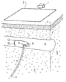
- a transmitter 1 which delivers an alternating current of 4 amperes to a loop 2.
- the transmitter 1 will normally have a maximum power output of 1000 W and preferably operates at two different frequencies, for instance a frequency of 200 Hz and a frequency of 2000 Hz.
- the geometric size of the loop 2 is from 100 x 100 m to 1000 x 1000 m.
- Located beneath the ground surface 3 is an earth layer 4 and beneath that a rock formation 5 which includes a rock cavity 6, for instance a drift or gallery.
- a borehole 7 extends vertically downwards in the rock formation 5, from the rock cavity 6.
- a probe 8 Positioned in the borehole 7 is a probe 8 equipped with three measuring coils, which are connected by a cable 9 to a receiver 10 and which can be raised and lowered in the borehole 7 by winding and unwinding the cable 9 onto and from a reel 11. Signals are sent from the probe 8 through the cable 9 to the receiver 10, which also receives signals from a reference coil 12 placed in the vicinity of the receiver 10 in the rock cavity 6 on a vibration-damping frame 13. Information relating to the phase of the primary field is continuously received by the receiver 10 from the reference coil 12.
- borehole assays can be made in old underground mines, e.g. deep prospecting with the intention of ascertaining whether or not mineral deposits are to be found beneath the mine.
- borehole assays can be made in old underground mines, e.g. deep prospecting with the intention of ascertaining whether or not mineral deposits are to be found beneath the mine. Since the primary field is measured continuously by a reference coil arranged in accordance with the invention, e.g. beneath the surface of the ground in existing mine passageways, the problem of needing to draw cables from the surface down into the mine is avoided. On the other hand, it is often a simple matter to draw a cable along the same level in a mine.
- a further advantage afforded by the invention is that measurements can be taken with the probe in several different boreholes which depart from one and the same level, while maintaining the reference measurement.
- Signals from the reference coil of the inventive arrangement are used to enable the relative phase of the received signal components to be determined at each point along the borehole and also to enable an absolute determination to be made of the phase position, by placing the reference coil in a position where the coil will not be disturbed by the conductor, such absolute determination of said phase position being otherwise particularly complicated. This provides a good basis on which to calculate the primary field and the subsequent calculation of the secondary field and conductor edges.
Applications Claiming Priority (2)
| Application Number | Priority Date | Filing Date | Title |
|---|---|---|---|
| SE9100018 | 1991-01-04 | ||
| SE9100018A SE9100018L (sv) | 1991-01-04 | 1991-01-04 | Saett foer elektromagnetisk bestaemning av ledande kroppars laege under markytan |
Publications (2)
| Publication Number | Publication Date |
|---|---|
| EP0494130A1 EP0494130A1 (en) | 1992-07-08 |
| EP0494130B1 true EP0494130B1 (en) | 1995-05-24 |
Family
ID=20381532
Family Applications (1)
| Application Number | Title | Priority Date | Filing Date |
|---|---|---|---|
| EP92850002A Expired - Lifetime EP0494130B1 (en) | 1991-01-04 | 1992-01-03 | Method and apparatus for electromagnetically detecting the locations of underground conductive bodies |
Country Status (6)
| Country | Link |
|---|---|
| US (1) | US5208539A ( ) |
| EP (1) | EP0494130B1 ( ) |
| AU (1) | AU640543B2 ( ) |
| CA (1) | CA2057326C ( ) |
| ES (1) | ES2072743T3 ( ) |
| SE (1) | SE9100018L ( ) |
Families Citing this family (9)
| Publication number | Priority date | Publication date | Assignee | Title |
|---|---|---|---|---|
| US5652519A (en) * | 1994-01-13 | 1997-07-29 | Jesse G. Robison | Method and apparatus for measuring pollutants contaminating earth formation |
| US5892362A (en) * | 1994-01-13 | 1999-04-06 | Jesse G. Robison | Method and apparatus for spacially continuous two-dimensional imaging of subsurface conditions through surface induction techniques |
| DE19547956A1 (de) * | 1995-12-21 | 1997-06-26 | Klaus Ebinger | Elektromagnetisches Suchverfahren und Sondenanordnung zur Ortung von unter der Oberfläche liegenden Objekten |
| SE9703429L (sv) * | 1997-09-23 | 1998-11-02 | Boliden Ab | Förfarande för elektromagnetisk sondering av borrhål jämte en sändar- och en mottagaranordning för förfarandets förverkligande |
| US6853194B2 (en) * | 2000-03-22 | 2005-02-08 | The Johns Hopkins University | Electromagnetic target discriminator sensor system and method for detecting and identifying metal targets |
| US6725161B1 (en) * | 2001-04-26 | 2004-04-20 | Applied Minds, Inc. | Method for locating and identifying underground structures with horizontal borehole to surface tomography |
| US6837105B1 (en) * | 2003-09-18 | 2005-01-04 | Baker Hughes Incorporated | Atomic clock for downhole applications |
| AU2015207977B2 (en) | 2014-08-06 | 2021-01-21 | Xcalibur Mph Switzerland Sa | Systems and methods for active cancellation of transient signals and dynamic loop configuration |
| CN107884834A (zh) * | 2017-10-19 | 2018-04-06 | 中煤科工集团西安研究院有限公司 | 同源多场瞬变电磁探测方法 |
Family Cites Families (6)
| Publication number | Priority date | Publication date | Assignee | Title |
|---|---|---|---|---|
| US2919397A (en) * | 1956-04-30 | 1959-12-29 | Lawrence W Morley | Method and apparatus for inductive prospecting |
| FR2283451A1 (fr) * | 1974-06-14 | 1976-03-26 | Rech Geolog Miniere | Methode et appareil de reconnaissance geophysique dans les forages par ondes tres basses frequences |
| AR207374A1 (es) * | 1974-09-13 | 1976-09-30 | Ciba Geigy Ag | Procedimiento para la obtencion de granulados de pigmentos dispersables que no producen polvillo |
| US4314251A (en) * | 1979-07-30 | 1982-02-02 | The Austin Company | Remote object position and orientation locater |
| GB2148012B (en) * | 1983-10-05 | 1987-04-01 | Robert Wesley Cobcroft | Induced magnetic field borehole surveying method and probe |
| AU577546B2 (en) * | 1983-10-05 | 1988-09-29 | Commonwealth Of Australia, The | Induced magnetic field borehole surveying method |
-
1991
- 1991-01-04 SE SE9100018A patent/SE9100018L/ not_active Application Discontinuation
- 1991-12-06 AU AU88870/91A patent/AU640543B2/en not_active Expired
- 1991-12-10 CA CA002057326A patent/CA2057326C/en not_active Expired - Lifetime
- 1991-12-30 US US07/815,809 patent/US5208539A/en not_active Expired - Lifetime
-
1992
- 1992-01-03 EP EP92850002A patent/EP0494130B1/en not_active Expired - Lifetime
- 1992-01-03 ES ES92850002T patent/ES2072743T3/es not_active Expired - Lifetime
Non-Patent Citations (1)
| Title |
|---|
| "Directional EM Measurements in Boreholes", R. Pantze, L. Malmqvist and G. Kristensson, from the Report "Borehole Geophysics for Mining and Geotechnical Applications", published in Geological Survey of Canada paper 85-27, Toronto, 1986, pages 79-88 * |
Also Published As
| Publication number | Publication date |
|---|---|
| SE9100018L (sv) | 1992-07-05 |
| CA2057326C (en) | 1995-11-07 |
| CA2057326A1 (en) | 1992-07-05 |
| US5208539A (en) | 1993-05-04 |
| AU640543B2 (en) | 1993-08-26 |
| SE9100018D0 (sv) | 1991-01-04 |
| ES2072743T3 (es) | 1995-07-16 |
| EP0494130A1 (en) | 1992-07-08 |
| AU8887091A (en) | 1992-07-09 |
Similar Documents
| Publication | Publication Date | Title |
|---|---|---|
| US6703838B2 (en) | Method and apparatus for measuring characteristics of geological formations | |
| CA2468193C (en) | Determination of borehole geometry inside cased wells with crosswell electromagnetics | |
| CA2642700C (en) | Method and apparatus for reducing induction noise in measurements made with a towed electromagnetic survey system | |
| GB2155182A (en) | Surveying and characterizing a region of an earth formation beneath a body of water | |
| GB2433604A (en) | Multi-component field sources for subsea exploration | |
| MX2011009449A (es) | Topografia electromagnetica usando campos electromagneticos que se presentan de manera natural como una fuente. | |
| EP1242963B1 (en) | Interferometric processing method to identify bed boundaries | |
| EP0494130B1 (en) | Method and apparatus for electromagnetically detecting the locations of underground conductive bodies | |
| US3391334A (en) | Resistivity logging based upon electromagnetic field measurements carried out with three vertically spaced detectors | |
| US4393350A (en) | Method for rapidly detecting subterranean tunnels by detecting a non-null value of a resultant horizontal magnetic field component | |
| Mahrer et al. | Radio frequency electromagnetic tunnel detection and delineation at the Otay Mesa site | |
| US4629990A (en) | Method and apparatus for correcting the relative motion of a transmitter and a receiver in airborne electromagnetic prospecting | |
| Bagrianski et al. | AFMAG evolution–expanding limits | |
| Jämtlid et al. | Electrical borehole measurements for the mapping of fracture zones in crystalline rock | |
| CA1174276A (en) | Method of determining the location of a deep-well casing by magnetic field sensing | |
| Balch et al. | Geophysics in mineral exploration: Fundamentals and case histories Ni-Cu sulphide deposits with examples from Voisey’s Bay | |
| Bozzo et al. | VLF prospecting: abservations about field experiments | |
| Parasnis | Large-layout harmonic field systems | |
| Harthill | Time-domain electromagnetic sounding | |
| Johnson et al. | A novel ground electromagnetic system | |
| Thiel | VLF surface impedance measurements at Zeehan, Tasmania | |
| Raab et al. | Electromagnetic System for Subsurface position Measurement | |
| ANDERSON et al. | Kristóf KAKAS*. Frank C. FRISCHKNECHT**, József ÚJSZÁSZI | |
| Cress et al. | Sensing of gradient electromagnetic fields from subsurface conducting targets | |
| Yakovlev et al. | New possibilities of audiomagnetotellurics in mineral exploration |
Legal Events
| Date | Code | Title | Description |
|---|---|---|---|
| PUAI | Public reference made under article 153(3) epc to a published international application that has entered the european phase |
Free format text: ORIGINAL CODE: 0009012 |
|
| AK | Designated contracting states |
Kind code of ref document: A1 Designated state(s): ES GB GR IT PT SE |
|
| 17P | Request for examination filed |
Effective date: 19921229 |
|
| 17Q | First examination report despatched |
Effective date: 19940128 |
|
| GRAA | (expected) grant |
Free format text: ORIGINAL CODE: 0009210 |
|
| AK | Designated contracting states |
Kind code of ref document: B1 Designated state(s): ES GB GR IT PT SE |
|
| REG | Reference to a national code |
Ref country code: ES Ref legal event code: FG2A Ref document number: 2072743 Country of ref document: ES Kind code of ref document: T3 |
|
| REG | Reference to a national code |
Ref country code: GR Ref legal event code: FG4A Free format text: 3016284 |
|
| ITF | It: translation for a ep patent filed |
Owner name: UFFICIO BREVETTI RICCARDI & C. |
|
| SC4A | Pt: translation is available |
Free format text: 950524 AVAILABILITY OF NATIONAL TRANSLATION |
|
| PLBE | No opposition filed within time limit |
Free format text: ORIGINAL CODE: 0009261 |
|
| STAA | Information on the status of an ep patent application or granted ep patent |
Free format text: STATUS: NO OPPOSITION FILED WITHIN TIME LIMIT |
|
| 26N | No opposition filed | ||
| REG | Reference to a national code |
Ref country code: GB Ref legal event code: IF02 |
|
| PG25 | Lapsed in a contracting state [announced via postgrant information from national office to epo] |
Ref country code: IT Free format text: LAPSE BECAUSE OF NON-PAYMENT OF DUE FEES;WARNING: LAPSES OF ITALIAN PATENTS WITH EFFECTIVE DATE BEFORE 2007 MAY HAVE OCCURRED AT ANY TIME BEFORE 2007. THE CORRECT EFFECTIVE DATE MAY BE DIFFERENT FROM THE ONE RECORDED. Effective date: 20050103 |
|
| PGRI | Patent reinstated in contracting state [announced from national office to epo] |
Ref country code: IT Effective date: 20080301 |
|
| PGFP | Annual fee paid to national office [announced via postgrant information from national office to epo] |
Ref country code: PT Payment date: 20101220 Year of fee payment: 20 |
|
| PGFP | Annual fee paid to national office [announced via postgrant information from national office to epo] |
Ref country code: GR Payment date: 20101221 Year of fee payment: 20 Ref country code: GB Payment date: 20101229 Year of fee payment: 20 |
|
| PGFP | Annual fee paid to national office [announced via postgrant information from national office to epo] |
Ref country code: IT Payment date: 20110115 Year of fee payment: 20 Ref country code: SE Payment date: 20110111 Year of fee payment: 20 |
|
| PGFP | Annual fee paid to national office [announced via postgrant information from national office to epo] |
Ref country code: ES Payment date: 20110216 Year of fee payment: 20 |
|
| REG | Reference to a national code |
Ref country code: PT Ref legal event code: MM4A Free format text: MAXIMUM VALIDITY LIMIT REACHED Effective date: 20120103 |
|
| REG | Reference to a national code |
Ref country code: GB Ref legal event code: PE20 Expiry date: 20120102 |
|
| PG25 | Lapsed in a contracting state [announced via postgrant information from national office to epo] |
Ref country code: GB Free format text: LAPSE BECAUSE OF EXPIRATION OF PROTECTION Effective date: 20120102 |
|
| REG | Reference to a national code |
Ref country code: SE Ref legal event code: EUG |
|
| REG | Reference to a national code |
Ref country code: GR Ref legal event code: MA Ref document number: 950401394 Country of ref document: GR Effective date: 20120104 |
|
| REG | Reference to a national code |
Ref country code: ES Ref legal event code: FD2A Effective date: 20120424 |
|
| PG25 | Lapsed in a contracting state [announced via postgrant information from national office to epo] |
Ref country code: PT Free format text: LAPSE BECAUSE OF EXPIRATION OF PROTECTION Effective date: 20120111 |
|
| PG25 | Lapsed in a contracting state [announced via postgrant information from national office to epo] |
Ref country code: ES Free format text: LAPSE BECAUSE OF EXPIRATION OF PROTECTION Effective date: 20120104 |