EP0493872B1 - Method and apparatus for image rotation - Google Patents
Method and apparatus for image rotation Download PDFInfo
- Publication number
- EP0493872B1 EP0493872B1 EP91307262A EP91307262A EP0493872B1 EP 0493872 B1 EP0493872 B1 EP 0493872B1 EP 91307262 A EP91307262 A EP 91307262A EP 91307262 A EP91307262 A EP 91307262A EP 0493872 B1 EP0493872 B1 EP 0493872B1
- Authority
- EP
- European Patent Office
- Prior art keywords
- value
- memory
- image
- coordinates
- incremented
- Prior art date
- Legal status (The legal status is an assumption and is not a legal conclusion. Google has not performed a legal analysis and makes no representation as to the accuracy of the status listed.)
- Expired - Lifetime
Links
- 238000000034 method Methods 0.000 title claims description 41
- 230000015654 memory Effects 0.000 claims description 59
- 230000009466 transformation Effects 0.000 description 12
- 230000008569 process Effects 0.000 description 9
- 239000011159 matrix material Substances 0.000 description 4
- 230000004044 response Effects 0.000 description 4
- 238000010586 diagram Methods 0.000 description 3
- 238000011426 transformation method Methods 0.000 description 3
- 230000003247 decreasing effect Effects 0.000 description 2
- 238000006073 displacement reaction Methods 0.000 description 2
- 230000006870 function Effects 0.000 description 2
- 230000009467 reduction Effects 0.000 description 2
- 238000000844 transformation Methods 0.000 description 2
- 238000007796 conventional method Methods 0.000 description 1
- 238000009795 derivation Methods 0.000 description 1
- 230000007246 mechanism Effects 0.000 description 1
- 238000003672 processing method Methods 0.000 description 1
Images


Classifications
-
- G—PHYSICS
- G06—COMPUTING; CALCULATING OR COUNTING
- G06T—IMAGE DATA PROCESSING OR GENERATION, IN GENERAL
- G06T3/00—Geometric image transformations in the plane of the image
- G06T3/60—Rotation of whole images or parts thereof
- G06T3/606—Rotation of whole images or parts thereof by memory addressing or mapping
-
- G—PHYSICS
- G06—COMPUTING; CALCULATING OR COUNTING
- G06T—IMAGE DATA PROCESSING OR GENERATION, IN GENERAL
- G06T3/00—Geometric image transformations in the plane of the image
- G06T3/60—Rotation of whole images or parts thereof
-
- G—PHYSICS
- G06—COMPUTING; CALCULATING OR COUNTING
- G06T—IMAGE DATA PROCESSING OR GENERATION, IN GENERAL
- G06T1/00—General purpose image data processing
- G06T1/20—Processor architectures; Processor configuration, e.g. pipelining
Definitions
- the present invention relates to an image processing method and apparatus, and more particularly to an image rotation method and an image rotation processing apparatus which can do high-speed real-time processing.
- image processing system using a computer carries out image processing functions such as reduction or enlargement of an image, rotation, etc. Since the image processing needs to process a great deal information at a high speed, a high-priced, special operation processing circuit is provided pertaining to each field. Accordingly, in a general personal computer which is not provided with the special operation processing circuit, image processing such as reduction, enlargement, rotation, etc. depends on software, so that the processing speed is slow and the real-time processing is difficult.
- the coordinates (x',y') of the new position can be obtained by four multiplication operations, based on the relations.
- a method of image rotation is described in an article "Hardware for image rotation by twice skew transformations" in the IEEE Transactions on Acoustics, Speech, and Signal Processing, Vol. ASSP-35, No. 4, April 1987, at pages 527 to 531.
- This describes a method of image rotation through an angle ⁇ in which the matrix relations described above are used to calculate the rotated x and y coordinates corresponding to a base pixel in the image before rotation and the rotated x and y coordinates of the pixels in the same row of the image before rotation as the base pixel are calculated by adding cos ⁇ and sin ⁇ to the rotated x and y coordinates of the base pixel respectively.
- the rotated x and y coordinates of a base pixel must be separately calculated for each row of the image before rotation.
- an image rotation processing apparatus which rotates an image of the magnitude M X N recorded in a first memory according to the given rotation angle ⁇ and the image magnitude M X N, by generating the coordinates x',y' of said second memory corresponding to the coordinates x,y of said first memory in order to record the image in the second memory, said apparatus comprising:
- the x,y notation and the principle of rows and columns of the array are purely arbitrary and in each case may be transposed.
- any reference to incrementing from 1 to M and/or 1 to N may equally be regarded as decreasing from M to 1 and/or N to 1. In such case(s) the relevant accumulator function by sequential subtraction rather than by incrementing.
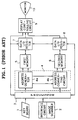
- the image processing system comprises a keyboard 1, an image input device 2, a processor 3, an address circuit 4, a first memory 5, a second memory 6, data I/O registers 7 and 8, a display controlling circuit 9, and a monitor 10.
- the keyboard 1 supplies data such as the image processing mode designation, the rotation angle ⁇ in an image rotation mode, the image magnitude M ⁇ N, etc., to the processor 3.
- the image input device 2 which receives the original image comprises an image scanner 2a and an interface circuit 2b.
- the processor 3 controls the system and processes the image data according to the given image processing program.
- the address circuit 4 comprises an address generator 4a and an address converting circuit 4b.
- the first memory 5 records an original image received from the image input device 2, and the second memory 6 records an image processed from the original image in the first memory 5.
- the data I/O registers 7 and 8 latch the data when the data, which is recorded or read in the first and second memories 5 and 6, is input or output.
- the display controlling circuit 9 receives the image data supplied from the processor 3, the first and second memories 5 and 6 and control the display on the monitor 10.
- An image is composed of M image element rows and N image element columns, thus forming an entire image of M ⁇ N image elements.
- the x value is initialized at zero and incremented by one, and when x becomes greater than the above number of horizontal image element rows M, the above rotational transformation ends. Conversely, until the above x value is not greater, the procedure proceeds to the next step 104.
- the y value is cleared to zero and incremented by one, and when y becomes greater than the above number of vertical image element columns N, the procedure loops back to the above step 102 where the x value is incremented by one. Conversely, until the above y value is not greater, the procedure proceeds to the next step 107.
- step 107 the image element coordinates x' and y' of the new position are computed based on the above relations (3), and in step 108, the pre-rotational image element coordinates (x,y) are stored in post-rotational image element coordinates (x',y'). Subsequently, the procedure loops back to the above step 105 where the y value is incremented by one.
- the pre-rotational image element coordinates (x,y) are transformed into post-rotational image element coordinates (x',y') through a specified angle ⁇ .
- the arithmetic process in the above step 107 requires four multiplication operations as shown in the above relations (3) for every increment of the x and y values.
- the system is designed so as to only rotate through certain angles such as 90° or 180° , so there exists the disadvantage of having to alter the hardware itself in order to rotate images through specific angles desired by the user.
- the image rotation method of the present invention to improve the conventional image rotation method is described with reference to FIG.3.
- the coordinates (x,y) of the first memory 5 are rotated through the relation angle ⁇ , the coordinates are rotated to the coordinates (X,Y).
- the x-axis coordinate values, (1,0), (2,0), (3,0) and (4,0) correspond to (cos ⁇ ,sin ⁇ ), (2cos ⁇ ,2sin ⁇ ), (3cos ⁇ , 3sin ⁇ ) and (4cos ⁇ ,4sin ⁇ ) of the X-axis.
- the y-axis coordinate values, (0,1), (0,2), (0,3), and (0,4) correspond to (-sin ⁇ , cos ⁇ ), (-2sin ⁇ , 2cos ⁇ ), (-3sin ⁇ , 3cos ⁇ ), (-4sin ⁇ ,4cos ⁇ ) of the Y-axis.
- relations (2) and (3) are derived from the relation (1) where the values of x and y are incremented from 1 through M and from 1 through N, respectively, and if, from relations (3), nx is said to equal ax and mx is said to equal bx, when x is at its initial value "1", then the following is true.
- step 203 the value of x and the rotation variables a and b are cleared to zero, and the value of x is incremented by one, and in the comparison of this incremented value of x with the number of horizontal image element rows M, if the value of x is larger, the image transformation ends. Conversely, if the value of x is not greater than M, the procedure proceeds to step 204 which performs the arithmetic operations of the above relations (4).
- step 205 the value of y is cleared to zero and the rotation variables a and b computed in the above step 204 are stored in x' and y' of the rotated coordinates (x', y'), respectively.
- step 206 the y value is incremented by one, and in step 207, the above incremented y value is compared with the number of vertical image element column N, and if the value of y is larger, the procedure loops back to the above step 202 where the value of x is incremented by one. Conversely, if the value of y is not greater than N, the procedure proceeds to the next step 208, thus ending the second procedure.
- step 208 the values x' and y' of the rotated coordinates (x', y') are computed by carrying out the addition operations corresponding to the above relations (5), and in step 209, the values of the coordinates (x, y) are stored in the coordinates (x', y') after being rotationally transformed, and the procedure loops back to the above step 206, thus ending the third procedure.
- an image composed of M ⁇ N image elements is rotationally transformed through a specified angle ⁇ .
- an image rotation according to this invention requires only one second, compared to 250 seconds for conventional image rotations, and because the speed of image rotation is increased dramatically, the process can be executed on widely used processors.
- FIG.5 is a block diagram showing an embodiment of the image rotation processing apparatus according to the present invention.
- This image rotation processing apparatus corresponds to the address converting circuit 4b of the address circuit shown in FIG.1 and comprises first to fourth accumulators A1 to A4 .
- the fourth accumulator circuit A4 receives the output value of the second accumulator circuit A2 and determines the y' coordinate value of the second memory 6 by the identical operation of the third accumulator circuit A3.
- Each of first and second accumulator circuits A1 and A2 respectively comprises adders 40 and 41 for summing the cosine value n or the sine value m and the accumulated value, registers 42 and 43 for recording the added results of the adders 40 and 41 and looping back the accumulated result to the adders 40 and 41 in response to control signals S1 and S2, whenever the value x is incremented by one, and transmitting gates 44 and 45 for transmitting the added results of the adders 40 and 41 to the output value in response to control signals S3 and S4, whenever the value x is incremented by one.
- Each of third and fourth accumulator circuits A3 and A4 respectively comprises adders 46 and 47 for adding the negative sine value (-m) or the sine value (n) into the accumulated value, registers 48 and 49 for being initialized to the output value supplied from the first or second accumulator circuit A1 or A2 whenever the value y is incremented by one, looping back the accumulated value to the adders 46 and 47 in response to control signals S5 and S6, whenever the value y is incremented by one, and recording the added results of the adders 46 and 47, and transmitting gates 50 and 51 for transmitting the added results of the adders 46 and 47 to the x' or y' coordinate value of the second memory in response to control signals S7 and S8, whenever the value y is incremented by one.
- this image rotation processing apparatus can be made using only adders. Accordingly, the constitution of the circuit is simplified and the cost reduced.
Landscapes
- Physics & Mathematics (AREA)
- General Physics & Mathematics (AREA)
- Engineering & Computer Science (AREA)
- Theoretical Computer Science (AREA)
- Image Processing (AREA)
- Digital Computer Display Output (AREA)
- Studio Circuits (AREA)
- Controls And Circuits For Display Device (AREA)
Description
- The present invention relates to an image processing method and apparatus, and more particularly to an image rotation method and an image rotation processing apparatus which can do high-speed real-time processing.
- Recently, introduced image processing system using a computer carries out image processing functions such as reduction or enlargement of an image, rotation, etc. Since the image processing needs to process a great deal information at a high speed, a high-priced, special operation processing circuit is provided pertaining to each field. Accordingly, in a general personal computer which is not provided with the special operation processing circuit, image processing such as reduction, enlargement, rotation, etc. depends on software, so that the processing speed is slow and the real-time processing is difficult.
- For example, when the image rotation method displays an image on an X-Y plane, and the coordinates of the present position of the image element are denoted (x,y), the coordinates of the resulting position of the image element after rotation through a specified angle are denoted (x',y'). These post-rotational image element coordinates (x',y') are easily obtained according to image transformation relations including the following matrix relations.
- The matrix relations are as follows.

- From the above matrix relations (1), the coordinate of the X-axis (hereon denoted x') and the coordinate of the Y-axis (hereon denoted y') of the image element coordinates (x', y') after rotational transformation are obtained. easily.

- Here, if the sine value (sin ) and the cosine value (cos ) of the rotational displacement resulting from rotation through the stated specified angle are denoted as first and second rotational displacement data (m, n) respectively, the relations (2) may be changed to the following relations (3).

- Therefore, if the X-axis point (hereon x) and the Y-axis point (hereon y) of the coordinates of the image element (x,y) before rotation are known, the coordinates (x',y') of the new position can be obtained by four multiplication operations, based on the relations.
- Thus, since the conventional method requires the four multiplication operations when the image rotates, a floating point multiplier is needed for the image rotation processing hardware. The image processing system of a general personal computer without such hardware processes the multiplication through software, but requires such a long time to do the four multiplication operations of the rotation, that real-time processing is difficult.
- A method of image rotation is described in an article "Hardware for image rotation by twice skew transformations" in the IEEE Transactions on Acoustics, Speech, and Signal Processing, Vol. ASSP-35, No. 4, April 1987, at pages 527 to 531. This describes a method of image rotation through an angle in which the matrix relations described above are used to calculate the rotated x and y coordinates corresponding to a base pixel in the image before rotation and the rotated x and y coordinates of the pixels in the same row of the image before rotation as the base pixel are calculated by adding cos and sin to the rotated x and y coordinates of the base pixel respectively. The rotated x and y coordinates of a base pixel must be separately calculated for each row of the image before rotation.
- It is an object of the present invention to provide an image rotation method which can do a high-speed, real-time processing, to solve the conventional problem.
- It is another object of the present invention to provide an image rotation processing apparatus which simplifies circuit constitution and reduces cost.
- According to a first aspect of the present invention, there is provided an image rotation method for rotating an image, which determines coordinates x',y' for a second memory for recording a rotated image from coordinates x,y of an M X N image in a first memory and transmits the data of the image elements related to the determined coordinates from said first memory to said second memory, to obtain the image rotated from the M X N image stored in the first memory by a specified angle using the reference point x=0, y=0 as a rotational axis, said method being characterised by comprising the steps of:
- (a) setting the value x=0 of said first memory , setting nominal values a=0 and b=0 and setting the cosine value of cos = n, the sine value sin =m and the negative sine value -sin =-m;
- (b) incrementing the value of x of said first memory by one; adding the initial values n,m to accumulated sums a,b respectively; setting the value y=0 of said first memory; and storing the values a,b as coordinates x',y' respectively, related to coordinates x,y of said first memory, in said second memory;
- (c) incrementing the value of y of said first memory; adding the values -m, n to the previously stored coordinates x',y' respectively; and storing data of the image elements related to coordinates x,y of said first memory, in said second memory at the new coordinates x', y';
- (d) repeating said step c a further N-1 times; and
- (e) repeating said steps b, c and d a further M-1 times.
-
- According to a second aspect of the present invention, there is provided an image rotation processing apparatus which rotates an image of the magnitude M X N recorded in a first memory according to the given rotation angle and the image magnitude M X N, by generating the coordinates x',y' of said second memory corresponding to the coordinates x,y of said first memory in order to record the image in the second memory, said apparatus comprising:
- an address generator for generating the coordinates x,y of said first memory corresponding to said given image magnitude M X N by the linear sequential scanning method wherein said address generator scans each line of said given image such that each line has a single x coordinate and a sequentially increasing y coordinate and such that each subsequently scanned line has a sequentially increasing x coordinate; and
- an address converting circuit, for generating the coordinates x',y' of the second
memory corresponding to the coordinates x,y of the first memory, characterised in that
said address converting circuit comprises:
- means for setting first, second, third and fourth accumulator means to zero;
- a first accumulator means, for cumulatively adding the cosine value cos=n, each time that said value x has been incremented by one, for determining a first sum a and for transmitting the value of said first sum a each time that said value x has been incremented by one,
- a second accumulator means, for cumulatively adding the sine value sin=m, each time that said x value has been incremented by one, for determining a second sum b and for transmitting the value of said second sum b each time that said value x has been incremented by one,
- a third accumulator means, operable to be initialised to the value of said first sum a from said first accumulator means whenever it is transmitted, for cumulatively adding the negative sine value -sin=-m, each time that said value y has been incremented by one, to said received value of said first sum a for determining the value of the coordinate x' and
- a fourth accumulator means, operable to be initialised to the value of said second sum b from said second accumulator means whenever it is transmitted, for cumulatively adding the cosine value cos=n, each time that said value y has been incremented by one, to said received value of said second sum b for determining the value of the coordinate y', and
- means for transmitting the image data stored in said first memory at coordinates x, y to coordinates x', y', generated by said third and fourth accumulator means, of said second memory each time that said value y has been incremented.
-
- In the context of the present invention, the x,y notation and the principle of rows and columns of the array are purely arbitrary and in each case may be transposed. Similarly, any reference to incrementing from 1 to M and/or 1 to N may equally be regarded as decreasing from M to 1 and/or N to 1. In such case(s) the relevant accumulator function by sequential subtraction rather than by incrementing.
- The above objects and other advantages of the present invention will become more apparent by describing the preferred embodiment of the present invention with reference to the attached drawings, in which:
- FIG. 1 is a block diagram schematically showing the constitution of the image processing system using a computer;
- FIG.2 is a flowchart showing the conventional rotation method;
- FIG.3 is a view for visualizing the image rotation method according to the present invention;
- FIG.4 is a flowchart showing a preferred embodiment of the image rotation method according to the present invention; and
- FIG.5 is a block diagram of a preferred embodiment of the image rotation processing apparatus according to the present invention.
-
- The present invention will be described in more detail with reference to the accompanying drawings.
- Referring to FIG.1, the image processing system comprises a keyboard 1, an image input device 2, a processor 3, an address circuit 4, a first memory 5, a second memory 6, data I/O registers 7 and 8, a display controlling circuit 9, and a monitor 10. The keyboard 1 supplies data such as the image processing mode designation, the rotation angle in an image rotation mode, the image magnitude M× N, etc., to the processor 3. The image input device 2 which receives the original image comprises an image scanner 2a and an interface circuit 2b. The processor 3 controls the system and processes the image data according to the given image processing program. The address circuit 4 comprises an address generator 4a and an address converting circuit 4b. The first memory 5 records an original image received from the image input device 2, and the second memory 6 records an image processed from the original image in the first memory 5. The data I/O registers 7 and 8 latch the data when the data, which is recorded or read in the first and second memories 5 and 6, is input or output. The display controlling circuit 9 receives the image data supplied from the processor 3, the first and second memories 5 and 6 and control the display on the monitor 10.
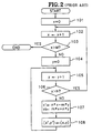
- In such an image processing system, the conventional image rotation method is described with reference to FIG.2 as follows.
- An image is composed of M image element rows and N image element columns, thus forming an entire image of M× N image elements.
- In the first portion of the procedure steps 101 to 103, the x value is initialized at zero and incremented by one, and when x becomes greater than the above number of horizontal image element rows M, the above rotational transformation ends. Conversely, until the above x value is not greater, the procedure proceeds to the next step 104.
- In the second portion of the following steps 104 to 106, the y value is cleared to zero and incremented by one, and when y becomes greater than the above number of vertical image element columns N, the procedure loops back to the above step 102 where the x value is incremented by one. Conversely, until the above y value is not greater, the procedure proceeds to the next step 107.
- Next, in step 107, the image element coordinates x' and y' of the new position are computed based on the above relations (3), and in step 108, the pre-rotational image element coordinates (x,y) are stored in post-rotational image element coordinates (x',y'). Subsequently, the procedure loops back to the above step 105 where the y value is incremented by one.
- Therefore, the pre-rotational image element coordinates (x,y) are transformed into post-rotational image element coordinates (x',y') through a specified angle . Here, the arithmetic process in the above step 107 requires four multiplication operations as shown in the above relations (3) for every increment of the x and y values.
- Accordingly, the above computer graphic system requires 4× M× N multiplication operations to rotate an image composed of M× N image elements, so that if M=2500 and N=2500, 25 million multiplication operations are carried out. If, for example, 10µs are required for one multiplication process in the above computer graphic system, approximately 250 seconds are required to rotate the image composed of M× N image elements, creating the disadvantage of a greatly decreased processing speed for the rotational transformation of images.
- Also, in a computer graphic system in which the geometric transformation mechanism which includes a rotational transformation means is realized through hardware, the system is designed so as to only rotate through certain angles such as 90° or 180° , so there exists the disadvantage of having to alter the hardware itself in order to rotate images through specific angles desired by the user.
- Furthermore, in the above computer graphic system for realizing rotational transformation method, special processors suited to such graphic processing are required, and there is the disadvantage that geometric transformations cannot be executed on widely used PCs (personal computers).
- The image rotation method of the present invention to improve the conventional image rotation method is described with reference to FIG.3. Referring to FIG.3, if the coordinates (x,y) of the first memory 5 are rotated through the relation angle , the coordinates are rotated to the coordinates (X,Y). The x-axis coordinate values, (1,0), (2,0), (3,0) and (4,0), correspond to (cos ,sin ), (2cos ,2sin ), (3cos , 3sin ) and (4cos ,4sin ) of the X-axis.
- Similarly, the y-axis coordinate values, (0,1), (0,2), (0,3), and (0,4) correspond to (-sin , cos ), (-2sin , 2cos ), (-3sin , 3cos ), (-4sin ,4cos ) of the Y-axis. That is, if sin is m and cos is n, the coordinate values on the X-axis (n,m), (n+n,m+m), (n+2n,m+2m) and (n+3n,m+3m) and the coordinate values on the Y-axis are denoted as (-m,n), (-m-m,n+n), (-m-2m,n+2n), (-m-3m,n+3n). Accordingly, if X sequentially varies from 1 to M, all of the X-Y coordinates can be obtained by accumulating the initial value to the initial value (n,m) and if Y sequentially varies from 1 to N, all of points on the X-Y plane can be obtained by accumulating the initial value to the initial value (-m,n). With this principle, the M× N image is sequentially scanned, and the increments of X and Y corresponding to the rotation angle are sequentially summed, so that the coordinates (x',y') of the rotated image can be obtained using only addition operations and without any multiplication.
- Accordingly, in an image transformation method and the apparatus thereof according to this invention, new relations which incorporate addition and not multiplication operations, and which form the rotational transformation relations on which the process for computing the new rotationally transformed coordinates (x',y') is based, are obtained as follows.
- The aforesaid relations (2) and (3) are derived from the relation (1) where the values of x and y are incremented from 1 through M and from 1 through N, respectively, and if, from relations (3), nx is said to equal ax and mx is said to equal bx, when x is at its initial value "1", then the following is true.
- Therefore, considering the case where the value of x is incremented by ones, the following relation (4) may be obtained from the above derivations.

- Also, considering the case where the value of y is incremented while the value of x remains constant, if the values of coordinates (x',y') of a rotational transformation through a specified angle of an image element in an arbitrary position with coordinates (x,y) prior to the rotation have been computed, the rotated coordinates (x',y') of the original coordinates (x,y) with an incremented value of y which is adjacent to the above pre-rotational coordinates (x,y) may be obtained from the following relations (5).Therefore, rotation variables a and b are computed when x is incremented by one, and the values of x' and y' of the rotated coordinates (x',y') are obtained through addition operations as y is incremented by one.

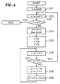
- A flowchart of a preferred embodiment of an image rotation method according to this invention including a process of addition operations based on the above relations (4) and (5) is described in detail with reference to FIG.4.
- In the first procedure from step 201 to step 203, the value of x and the rotation variables a and b are cleared to zero, and the value of x is incremented by one, and in the comparison of this incremented value of x with the number of horizontal image element rows M, if the value of x is larger, the image transformation ends. Conversely, if the value of x is not greater than M, the procedure proceeds to step 204 which performs the arithmetic operations of the above relations (4). In step 205, the value of y is cleared to zero and the rotation variables a and b computed in the above step 204 are stored in x' and y' of the rotated coordinates (x', y'), respectively. In step 206, the y value is incremented by one, and in step 207, the above incremented y value is compared with the number of vertical image element column N, and if the value of y is larger, the procedure loops back to the above step 202 where the value of x is incremented by one. Conversely, if the value of y is not greater than N, the procedure proceeds to the next step 208, thus ending the second procedure. In step 208, the values x' and y' of the rotated coordinates (x', y') are computed by carrying out the addition operations corresponding to the above relations (5), and in step 209, the values of the coordinates (x, y) are stored in the coordinates (x', y') after being rotationally transformed, and the procedure loops back to the above step 206, thus ending the third procedure. By carrying out the above procedures, an image composed of M× N image elements is rotationally transformed through a specified angle .
- An image transformation method and the apparatus thereof according to this invention employs a process including addition operations instead of conventional multiplication operations, and thus 2× M× N addition operations are required in rotating an image composed of M× N image elements through a specified angle , and for example, if M=2500 and N=2500, approximately 12,500,000 addition operations are required.
- Therefore, since a computer system's addition operations require less time relative to multiplication operations, and supposing 50ns are required for one addition operation, rotating the entire image by a specified angle would require approximately 1 second.
- Thus, an image rotation according to this invention requires only one second, compared to 250 seconds for conventional image rotations, and because the speed of image rotation is increased dramatically, the process can be executed on widely used processors.
- The above is a description of an image rotational transformation realized through software and may be applied to an image processing system having the constitution such as the one shown in FIG.1.
- FIG.5 is a block diagram showing an embodiment of the image rotation processing apparatus according to the present invention.
- This image rotation processing apparatus corresponds to the address converting circuit 4b of the address circuit shown in FIG.1 and comprises first to fourth accumulators A1 to A4 . The first accumulator circuit A1 accumulates the cosine value (cos =n) corresponding to the rotation angle of the unit value (1,0) of the value x of the first memory 5 whenever the value x is incremented by one. The second accumulator circuit A2 accumulates the sine value (sin =m) corresponding to the rotation angle of the unit value (1,0) of the value x of the first memory 5 whenever the value x is incremented by one. The third accumulator circuit A3 adds the negative sine value (-sin =-m) corresponding to the rotation angle of the unit value (0,1) of the value y of the first memory 5 into the output value of the first accumulator circuit A1, and accumulates the negative sine value (-m) into the added value whenever the value y is incremented by one, thus determining the accumulated value as the x' coordinate value of the second memory 6. The fourth accumulator circuit A4 receives the output value of the second accumulator circuit A2 and determines the y' coordinate value of the second memory 6 by the identical operation of the third accumulator circuit A3.
- Each of first and second accumulator circuits A1 and A2 respectively comprises adders 40 and 41 for summing the cosine value n or the sine value m and the accumulated value, registers 42 and 43 for recording the added results of the adders 40 and 41 and looping back the accumulated result to the adders 40 and 41 in response to control signals S1 and S2, whenever the value x is incremented by one, and transmitting gates 44 and 45 for transmitting the added results of the adders 40 and 41 to the output value in response to control signals S3 and S4, whenever the value x is incremented by one.
- Each of third and fourth accumulator circuits A3 and A4 respectively comprises adders 46 and 47 for adding the negative sine value (-m) or the sine value (n) into the accumulated value, registers 48 and 49 for being initialized to the output value supplied from the first or second accumulator circuit A1 or A2 whenever the value y is incremented by one, looping back the accumulated value to the adders 46 and 47 in response to control signals S5 and S6, whenever the value y is incremented by one, and recording the added results of the adders 46 and 47, and transmitting gates 50 and 51 for transmitting the added results of the adders 46 and 47 to the x' or y' coordinate value of the second memory in response to control signals S7 and S8, whenever the value y is incremented by one.
- Thus, without a floating point multiplier, this image rotation processing apparatus can be made using only adders. Accordingly, the constitution of the circuit is simplified and the cost reduced.
Claims (4)
- An image rotation method for rotating an image, which determines coordinates x',y' for a second memory (6) for recording a rotated image from coordinates x,y of an M X N image in a first memory (5) and transmits the data of the image elements related to the determined coordinates from said first memory (5) to said second memory (6), to obtain the image rotated from the M X N image stored in the first memory (5) by a specified angle using the reference point x=0, y=0 as a rotational axis, said method being characterised by comprising the steps of:(a) setting the value x=0 of said first memory (5), setting nominal values a=0 and b=0 and setting the cosine value of cos = n, the sine value sin =m and the negative sine value -sin =-m;(b) incrementing the value of x of said first memory (5) by one; adding the initial values n,m to accumulated sums a,b respectively; setting the value y=0 of said first memory (5); and storing the values a,b as coordinates x',y' respectively, related to coordinates x,y of said first memory (5), in said second memory (6);(c) incrementing the value of y of said first memory (5); adding the values -m, n to the previously stored coordinates x',y' respectively; and storing data of the image elements related to coordinates x,y of said first memory (5), in said second memory (6) at the new coordinates x', y';(d) repeating said step (c) a further N-1 times; and(e) repeating said steps (b), (c) and (d) a further M-1 times.
- An image rotation processing apparatus which rotates an image of the magnitude M X N recorded in a first memory (5) according to the given rotation angle and the image magnitude M X N, by generating the coordinates x',y' of said second memory (6) corresponding to the coordinates x,y of said first memory (5) in order to record the image in the second memory (6), said apparatus comprising:an address generator (4a) for generating the coordinates x,y of said first memory (5) corresponding to said given image magnitude M X N by the linear sequential scanning method wherein said address generator scans each line of said given image such that each line has a single x coordinate and a sequentially increasing y coordinate and such that each subsequently scanned line has a sequentially increasing x coordinate; andan address converting circuit (4b), for generating the coordinates x',y' of the second memory corresponding to the coordinates x,y of the first memory, characterised in that said address converting circuit comprises:means for setting first, second, third and fourth accumulator means to zero;a first accumulator means (A1), for cumulatively adding the cosine value cos=n, each time that said value x has been incremented by one, for determining a first sum a and for transmitting the value of said first sum a each time that said value x has been incremented by one,a second accumulator means (A2), for cumulatively adding the sine value sin =m, each time that said x value has been incremented by one, for determining a second sum b and for transmitting the value of said second sum b each time that said value x has been incremented by one,a third accumulator means (A3), operable to be initialised to the value of said first sum a from said first accumulator means (A1) whenever it is transmitted, for cumulatively adding the negative sine value -sin=-m, each time that said value y has been incremented by one, to said received value of said first sum a for determining the value of the coordinate x', anda fourth accumulator means (A4), operable to be initialised to the value of said second sum b from said second accumulator means (A2) whenever it is transmitted, for cumulatively adding the cosine value cos=n, each time that said value y has been incremented by one, to said received value of said second sum b for determining the value of the coordinate y', andmeans for transmitting the image data stored in said first memory at coordinates x, y to coordinates x', y', generated by said third and fourth accumulator means, of said second memory each time that said value y has been incremented.
- An image rotation processing apparatus as claimed in claim 2, wherein each of said first and second accumulator means (A1, A2) comprises:an adder (40 or 41) for adding said cosine value n or said sine value m into the accumulated result value;a register (42 or 43) for recording the added result of said adder (40 or 41) and looping back the accumulated result value of said adder (40 or 41) whenever the value of x is incremented by one; anda transmitting gate (44 or 45) for transmitting the added result of said adder (40 or 41) to the output value thereof whenever the value of x is incremented by one.
- An image rotation processing apparatus as claimed in claim 2, wherein each of said third and fourth accumulator means (A3, A4) comprises:an adder (46 or 47) for adding said negative sine value -m or cosine value n into the accumulated result value;a register (48 or 49) for being initialized to the output value supplied from said first or second accumulator means (A3 or A4) whenever the value x is incremented by one, recording the added result of said adder whenever the value y is incremented by one, and looping back the accumulated result value into said adder; anda transmitting gate (50 or 51) for transmitting the added result of said adder to the value of the coordinate x' or y' of the second memory (6) whenever the value y is incremented by one.
Applications Claiming Priority (2)
| Application Number | Priority Date | Filing Date | Title |
|---|---|---|---|
| KR2275790 | 1990-12-31 | ||
| KR1019900022757A KR930007023B1 (en) | 1990-12-31 | 1990-12-31 | Method and apparatus for transforming image |
Publications (3)
| Publication Number | Publication Date |
|---|---|
| EP0493872A2 EP0493872A2 (en) | 1992-07-08 |
| EP0493872A3 EP0493872A3 (en) | 1994-03-16 |
| EP0493872B1 true EP0493872B1 (en) | 2002-03-06 |
Family
ID=19309181
Family Applications (1)
| Application Number | Title | Priority Date | Filing Date |
|---|---|---|---|
| EP91307262A Expired - Lifetime EP0493872B1 (en) | 1990-12-31 | 1991-08-07 | Method and apparatus for image rotation |
Country Status (6)
| Country | Link |
|---|---|
| US (1) | US5295237A (en) |
| EP (1) | EP0493872B1 (en) |
| JP (1) | JP2873112B2 (en) |
| KR (1) | KR930007023B1 (en) |
| CA (1) | CA2047984C (en) |
| DE (1) | DE69132947T2 (en) |
Families Citing this family (18)
| Publication number | Priority date | Publication date | Assignee | Title |
|---|---|---|---|---|
| US5475803A (en) * | 1992-07-10 | 1995-12-12 | Lsi Logic Corporation | Method for 2-D affine transformation of images |
| US5715385A (en) * | 1992-07-10 | 1998-02-03 | Lsi Logic Corporation | Apparatus for 2-D affine transformation of images |
| JPH07282270A (en) * | 1994-04-08 | 1995-10-27 | Sony Corp | Method and device for image generation |
| US5751293A (en) * | 1994-08-24 | 1998-05-12 | Nippon Telegraph And Telephone Corp. | Pattern generation method and apparatus for automatic generation of continuous tile patterns along any arbitrary side |
| JPH08249422A (en) * | 1995-03-08 | 1996-09-27 | Canon Inc | Device and method for character processing |
| US5870581A (en) * | 1996-12-20 | 1999-02-09 | Oak Technology, Inc. | Method and apparatus for performing concurrent write operations to a single-write-input register file and an accumulator register |
| US5946222A (en) * | 1996-12-20 | 1999-08-31 | Oak Technology, Inc. | Method and apparatus for performing a masked byte addition operation |
| KR100444899B1 (en) * | 1997-05-07 | 2004-12-08 | 삼성전자주식회사 | Rotation transformation method for images to reduce operation quantity |
| US6223181B1 (en) | 1997-07-31 | 2001-04-24 | Oak Technology, Inc. | Memory conserving and compression technique-compatible image rotation system |
| US5956043A (en) * | 1997-09-18 | 1999-09-21 | Novell, Inc. | Textured tile rotation system and method |
| US6184896B1 (en) * | 1999-01-08 | 2001-02-06 | Sun Microsystems, Inc. | System and method for improved rendering of graphical rotations |
| AU730778B2 (en) * | 1999-03-19 | 2001-03-15 | Canon Kabushiki Kaisha | Method and apparatus for rotating digital images |
| IL136373A0 (en) * | 2000-05-25 | 2001-06-14 | Itpen Ltd Partnership Israel | Representation of three-dimensional bodies on computer screens and games involving such representations |
| US6816625B2 (en) | 2000-08-16 | 2004-11-09 | Lewis Jr Clarence A | Distortion free image capture system and method |
| GB2387519B (en) * | 2002-04-08 | 2005-06-22 | Canon Europa Nv | Viewing controller for three-dimensional computer graphics |
| US7068856B2 (en) | 2002-09-17 | 2006-06-27 | Lockheed Martin Corporation | Method and system for determining and correcting image orientation angle |
| US9561008B2 (en) | 2010-12-28 | 2017-02-07 | General Electric Company | Method of displaying image |
| US20190295222A1 (en) * | 2018-03-22 | 2019-09-26 | Seiko Epson Corporation | Image processing device, image processing method, and display device |
Family Cites Families (8)
| Publication number | Priority date | Publication date | Assignee | Title |
|---|---|---|---|---|
| JPS61201375A (en) * | 1985-03-04 | 1986-09-06 | Ricoh Co Ltd | Image rotation system |
| JPS62244095A (en) * | 1986-04-16 | 1987-10-24 | セイコーインスツルメンツ株式会社 | Display unit |
| JPH0661103B2 (en) * | 1986-07-22 | 1994-08-10 | 日本電気株式会社 | Rotational figure generator |
| US4929085A (en) * | 1986-09-30 | 1990-05-29 | Kabushiki Kaisha Toshiba | Image data rotation processing method and apparatus therefor |
| JP2636225B2 (en) * | 1987-02-03 | 1997-07-30 | 松下電器産業株式会社 | Image rotation device |
| US4985849A (en) * | 1987-06-12 | 1991-01-15 | Canon Kabushiki Kaisha | Image processing system for forming a slantwise-mapped or rotated modified image of an original image |
| US5081700A (en) * | 1989-02-15 | 1992-01-14 | Unisys Corporation | Apparatus for high speed image rotation |
| US5067167A (en) * | 1990-10-10 | 1991-11-19 | Cornell Research Foundation, Inc. | Apparatus and method for rotating of three-dimensional images |
-
1990
- 1990-12-31 KR KR1019900022757A patent/KR930007023B1/en not_active IP Right Cessation
-
1991
- 1991-07-26 CA CA002047984A patent/CA2047984C/en not_active Expired - Fee Related
- 1991-08-05 US US07/740,137 patent/US5295237A/en not_active Expired - Lifetime
- 1991-08-07 EP EP91307262A patent/EP0493872B1/en not_active Expired - Lifetime
- 1991-08-07 DE DE69132947T patent/DE69132947T2/en not_active Expired - Fee Related
- 1991-08-08 JP JP3199054A patent/JP2873112B2/en not_active Expired - Fee Related
Also Published As
| Publication number | Publication date |
|---|---|
| DE69132947T2 (en) | 2002-06-27 |
| EP0493872A2 (en) | 1992-07-08 |
| KR930007023B1 (en) | 1993-07-26 |
| JPH04276870A (en) | 1992-10-01 |
| US5295237A (en) | 1994-03-15 |
| KR920013182A (en) | 1992-07-28 |
| EP0493872A3 (en) | 1994-03-16 |
| JP2873112B2 (en) | 1999-03-24 |
| DE69132947D1 (en) | 2002-04-11 |
| CA2047984A1 (en) | 1992-07-01 |
| CA2047984C (en) | 1996-12-17 |
Similar Documents
| Publication | Publication Date | Title |
|---|---|---|
| EP0493872B1 (en) | Method and apparatus for image rotation | |
| EP0396311B1 (en) | Image processing apparatus and method | |
| Danielsson et al. | High-accuracy rotation of images | |
| US5008752A (en) | Digital image interpolator with multiple interpolation algorithms | |
| US4667236A (en) | Television perspective effects system | |
| TWI315056B (en) | Block-based rotation of arbitrary-shaped images | |
| JPS6039271A (en) | Method and apparatus for realizing expansive and invasive conversion in digital image processing | |
| JPH0212570A (en) | Picture processor | |
| US5241626A (en) | Image processing apparatus having improved two-dimensional address generator | |
| JPS6217236B2 (en) | ||
| JP3055024B2 (en) | Image data transfer device | |
| JP4832462B2 (en) | Image processing apparatus, image processing program, and image processing method | |
| JP2973819B2 (en) | Image processing device | |
| JP2967228B2 (en) | Image data transfer device | |
| JP3397838B2 (en) | Image processing apparatus and discrete cosine transform method | |
| JP2874221B2 (en) | Arithmetic control circuit | |
| Xu et al. | A Fast Implementation of Image Rotation with Bresenham’s Line-Scanning Algorithm | |
| JPH0462105B2 (en) | ||
| JP2512252B2 (en) | Image scaling device | |
| JPH0863595A (en) | Method and device for rotation processing of image | |
| JPH0480428B2 (en) | ||
| JPH011072A (en) | Image processing device | |
| JPH04284580A (en) | Address generating circuit | |
| JPH10327429A (en) | Image processing method and image processor | |
| JPH07182505A (en) | Image rotating device for printing |
Legal Events
| Date | Code | Title | Description |
|---|---|---|---|
| PUAI | Public reference made under article 153(3) epc to a published international application that has entered the european phase |
Free format text: ORIGINAL CODE: 0009012 |
|
| AK | Designated contracting states |
Kind code of ref document: A2 Designated state(s): DE FR GB IT NL |
|
| PUAL | Search report despatched |
Free format text: ORIGINAL CODE: 0009013 |
|
| AK | Designated contracting states |
Kind code of ref document: A3 Designated state(s): DE FR GB IT NL |
|
| 17P | Request for examination filed |
Effective date: 19940712 |
|
| 17Q | First examination report despatched |
Effective date: 19961106 |
|
| GRAG | Despatch of communication of intention to grant |
Free format text: ORIGINAL CODE: EPIDOS AGRA |
|
| GRAG | Despatch of communication of intention to grant |
Free format text: ORIGINAL CODE: EPIDOS AGRA |
|
| GRAH | Despatch of communication of intention to grant a patent |
Free format text: ORIGINAL CODE: EPIDOS IGRA |
|
| GRAH | Despatch of communication of intention to grant a patent |
Free format text: ORIGINAL CODE: EPIDOS IGRA |
|
| REG | Reference to a national code |
Ref country code: GB Ref legal event code: IF02 |
|
| GRAA | (expected) grant |
Free format text: ORIGINAL CODE: 0009210 |
|
| RIN1 | Information on inventor provided before grant (corrected) |
Inventor name: PARK, YOU-KEUN |
|
| AK | Designated contracting states |
Kind code of ref document: B1 Designated state(s): DE FR GB IT NL |
|
| RIC1 | Information provided on ipc code assigned before grant |
Free format text: 7G 06T 3/60 A |
|
| REF | Corresponds to: |
Ref document number: 69132947 Country of ref document: DE Date of ref document: 20020411 |
|
| ET | Fr: translation filed | ||
| PLBE | No opposition filed within time limit |
Free format text: ORIGINAL CODE: 0009261 |
|
| STAA | Information on the status of an ep patent application or granted ep patent |
Free format text: STATUS: NO OPPOSITION FILED WITHIN TIME LIMIT |
|
| 26N | No opposition filed |
Effective date: 20021209 |
|
| PGFP | Annual fee paid to national office [announced via postgrant information from national office to epo] |
Ref country code: DE Payment date: 20070802 Year of fee payment: 17 |
|
| PGFP | Annual fee paid to national office [announced via postgrant information from national office to epo] |
Ref country code: GB Payment date: 20070801 Year of fee payment: 17 |
|
| PGFP | Annual fee paid to national office [announced via postgrant information from national office to epo] |
Ref country code: NL Payment date: 20070805 Year of fee payment: 17 Ref country code: IT Payment date: 20070828 Year of fee payment: 17 |
|
| PGFP | Annual fee paid to national office [announced via postgrant information from national office to epo] |
Ref country code: FR Payment date: 20070808 Year of fee payment: 17 |
|
| GBPC | Gb: european patent ceased through non-payment of renewal fee |
Effective date: 20080807 |
|
| NLV4 | Nl: lapsed or anulled due to non-payment of the annual fee |
Effective date: 20090301 |
|
| PG25 | Lapsed in a contracting state [announced via postgrant information from national office to epo] |
Ref country code: NL Free format text: LAPSE BECAUSE OF NON-PAYMENT OF DUE FEES Effective date: 20090301 |
|
| REG | Reference to a national code |
Ref country code: FR Ref legal event code: ST Effective date: 20090430 |
|
| PG25 | Lapsed in a contracting state [announced via postgrant information from national office to epo] |
Ref country code: IT Free format text: LAPSE BECAUSE OF NON-PAYMENT OF DUE FEES Effective date: 20080807 Ref country code: FR Free format text: LAPSE BECAUSE OF NON-PAYMENT OF DUE FEES Effective date: 20080901 Ref country code: DE Free format text: LAPSE BECAUSE OF NON-PAYMENT OF DUE FEES Effective date: 20090303 |
|
| PG25 | Lapsed in a contracting state [announced via postgrant information from national office to epo] |
Ref country code: GB Free format text: LAPSE BECAUSE OF NON-PAYMENT OF DUE FEES Effective date: 20080807 |