EP0493397B2 - Pressure transmitter with flame isolating plug - Google Patents
Pressure transmitter with flame isolating plug Download PDFInfo
- Publication number
- EP0493397B2 EP0493397B2 EP90912186A EP90912186A EP0493397B2 EP 0493397 B2 EP0493397 B2 EP 0493397B2 EP 90912186 A EP90912186 A EP 90912186A EP 90912186 A EP90912186 A EP 90912186A EP 0493397 B2 EP0493397 B2 EP 0493397B2
- Authority
- EP
- European Patent Office
- Prior art keywords
- sensor
- passageway
- flame
- transmitter
- block
- Prior art date
- Legal status (The legal status is an assumption and is not a legal conclusion. Google has not performed a legal analysis and makes no representation as to the accuracy of the status listed.)
- Expired - Lifetime
Links
Images
Classifications
-
- G—PHYSICS
- G01—MEASURING; TESTING
- G01L—MEASURING FORCE, STRESS, TORQUE, WORK, MECHANICAL POWER, MECHANICAL EFFICIENCY, OR FLUID PRESSURE
- G01L19/00—Details of, or accessories for, apparatus for measuring steady or quasi-steady pressure of a fluent medium insofar as such details or accessories are not special to particular types of pressure gauges
- G01L19/0007—Fluidic connecting means
- G01L19/0038—Fluidic connecting means being part of the housing
-
- G—PHYSICS
- G01—MEASURING; TESTING
- G01L—MEASURING FORCE, STRESS, TORQUE, WORK, MECHANICAL POWER, MECHANICAL EFFICIENCY, OR FLUID PRESSURE
- G01L7/00—Measuring the steady or quasi-steady pressure of a fluid or a fluent solid material by mechanical or fluid pressure-sensitive elements
- G01L7/02—Measuring the steady or quasi-steady pressure of a fluid or a fluent solid material by mechanical or fluid pressure-sensitive elements in the form of elastically-deformable gauges
- G01L7/08—Measuring the steady or quasi-steady pressure of a fluid or a fluent solid material by mechanical or fluid pressure-sensitive elements in the form of elastically-deformable gauges of the flexible-diaphragm type
-
- G—PHYSICS
- G01—MEASURING; TESTING
- G01L—MEASURING FORCE, STRESS, TORQUE, WORK, MECHANICAL POWER, MECHANICAL EFFICIENCY, OR FLUID PRESSURE
- G01L19/00—Details of, or accessories for, apparatus for measuring steady or quasi-steady pressure of a fluent medium insofar as such details or accessories are not special to particular types of pressure gauges
- G01L19/0061—Electrical connection means
- G01L19/0084—Electrical connection means to the outside of the housing
-
- G—PHYSICS
- G01—MEASURING; TESTING
- G01L—MEASURING FORCE, STRESS, TORQUE, WORK, MECHANICAL POWER, MECHANICAL EFFICIENCY, OR FLUID PRESSURE
- G01L19/00—Details of, or accessories for, apparatus for measuring steady or quasi-steady pressure of a fluent medium insofar as such details or accessories are not special to particular types of pressure gauges
- G01L19/06—Means for preventing overload or deleterious influence of the measured medium on the measuring device or vice versa
- G01L19/0627—Protection against aggressive medium in general
- G01L19/0645—Protection against aggressive medium in general using isolation membranes, specially adapted for protection
-
- G—PHYSICS
- G01—MEASURING; TESTING
- G01L—MEASURING FORCE, STRESS, TORQUE, WORK, MECHANICAL POWER, MECHANICAL EFFICIENCY, OR FLUID PRESSURE
- G01L19/00—Details of, or accessories for, apparatus for measuring steady or quasi-steady pressure of a fluent medium insofar as such details or accessories are not special to particular types of pressure gauges
- G01L19/06—Means for preventing overload or deleterious influence of the measured medium on the measuring device or vice versa
- G01L19/0663—Flame protection; Flame barriers
-
- G—PHYSICS
- G01—MEASURING; TESTING
- G01L—MEASURING FORCE, STRESS, TORQUE, WORK, MECHANICAL POWER, MECHANICAL EFFICIENCY, OR FLUID PRESSURE
- G01L19/00—Details of, or accessories for, apparatus for measuring steady or quasi-steady pressure of a fluent medium insofar as such details or accessories are not special to particular types of pressure gauges
- G01L19/14—Housings
- G01L19/142—Multiple part housings
- G01L19/143—Two part housings
Definitions
- the present invention relates to flame arresting or quenching plugs for use with transmitter housings.
- Flammable mixtures many times are present in an atmosphere outside a pressure transmitter or in a process fluid which is being sensed by a pressure sensor in the transmitter.
- Various types of protection reduce the likelihood that an ignition of flammable gas inside the transmitter will ignite a flammable mixture outside the transmitter.
- Transmitter openings and covers for the openings are now made so as to cool ignited gas Inside the transmitter housing as it is venting to a temperature below that needed to ignite a flammable mixture outside the transmitter.
- the ignited gasses in the transmitter are cooled as they travel along narrow passageways such as flanges or threads between a housing and a cover of the transmitter. As the hot gases move along the passageway, heat is transferred from the flame to the wails forming the passageway.
- the passageway is narrow enough, more heat is transferred from the flame to the housing and cover than is produced by the flame, and the flame front cools. If the passageway is also long enough, the flame front can be cooled to a temperature low enough to quench the flame, thereby preventing ignited gases from moving further down the passageway and igniting a flammable mixture outside the transmitter.
- a flame quenching path effectively contain ignition of a flammable mixture inside the housing even after resilient seals such as O-rings and thin foil barriers such as isolator diaphragms have been damaged or removed, or after isolator liquids have leaked out, or welds have failed.
- Flame quenching between the sensor, which includes electrical circuitry capable of generating a spark under fault conditions, and the outside of the transmitter is a problem because there is a need to expose the sensor to the process fluid pressure, and, in the case of a gauge pressure transmitter, there is also a need to expose the sensor to atmospheric pressure outside the transmitter, as well. Flame quenching paths between sensors in a transmitter housing and the outside of the transmitter have been provided, but prior art arrangements such as class I threads are difficult to make in applications for holding a sensor in place and expensive to manufacture.
- the present invention is as set out in claim 1.
- peripheral surface of the plug and the adjacent wall form an interspace shaped to resist the passage of flame thus flame-isolating any ignited gases from the atmosphere.
- the plug has a second passageway coupling the sensor to the atmosphere.
- the second passageway is formed in a shape that resists travel of a flame, and thus flame-isolating the sensor from the atmosphere.
- the second passageway couples to the atmosphere via the interspace.
- Atypical transmitter housing illustrated generally at 10 includes a body 11 having a first circuit compartment 12, and a terminal block compartment 13.
- the terminal block compartment has a threaded cover 14 thereon for access to terminal screws 15 mounted on the terminal block 16.
- a circuit is represented at 20 in the circuit compartment
- the circuit can be conventional, as now used with two-wire transmitters that are well known in the art.
- the transmitter housing has a hole or opening 22 defined in a wall thereof leading to the circuit compartment, and hole 22 leads to the interior of a sleeve 23.
- the interior surface of sleeve 23 is threaded as at 24 for receiving a plug assembly 25, which includes a sleeve-like fitting 26 that has a threaded neck 27 mating with interior rouge 1 threads 24 on the interior of the sleeve 23.
- the threads 24 of sleeve 23 and the threaded neck 27 of plug 26 are class 1 threads to provide for a close fit to insure that there is a flame arresting path defined along this juncture. These threads are expensive to make, so the number of places they are used should be minimized.
- a roll pin 30 is positioned through a radial opening in the sleeve 23 to extend into a groove 31 in the sleeve-like fitting 26 to provide for an anti-rotation stop for the plug assembly 25.
- the sleeve-like fitting 26 has a smaller diameter inner end that fits within the opening 22, and has an internal passageway indicated generally at 32 which includes a passageway portion 33 above a capture ring 34 defined about midway along the length of the sleeve-like fitting 26.
- the interior passageway portion 33 is of size to receive an isolator block 35, which has an O-ring seal 36 around the periphery thereof that seals on the interior of passageway portion 33.
- the interior surface of fitting 26 which forms passageway 33 is very precisely machined, and the outer surface of the isolator block 35 Is also precisely machined to leave a maximum space of .004 inches between the surface of plug 26 which forms the passageway 33 and the outer surface of the isolator block 35. This spacing also provides a flame quenching path of a shape that is of sufficient length and appropriate clearance to arrest or quench a flame which may be venting from the circuit compartment 12 to the exterior.
- the isolator block 35 forms part of a sensor assembly 40.
- the isolator block 35 is fixed to a sensor support block 41 with a suitable peripheral weld indicated at 42.
- the sensor support block 41 is cylindrical and fits into the opening 22 in the housing wall, and has an O-ring seal 43 around the periphery at approximately its midsection to seal the opening 22 with respect to the circuit compartment 12.
- the support block 41 is formed with a suitable recess indicated at 44 on an end thereof facing the isolator block 35.
- Recess 44 has a support surface that supports a silicon chip diaphragm type pressure sensor 45.
- Suitable mounting material 46 can be used for mounting a sensor base to the surface of sensor support block 41.
- the sensor base has a diaphragm section 47 supported thereon to provide for the sensing of pressure present in the recess or chamber 44.
- a recess 50 is provided behind the base of the silicon chip 45 and is open to a small diameter hole 51 that is a maximum of 0.381 mm (.015 inches) in diameter, and which extends radially outward to an interspace indicated at 52 between the outer periphery of the sensor support block 41 and the surface of hole 22.
- the interspace 52 is open to the threads 24 retaining the fitting 26.
- the sensor support block 41 has a pair of holes 53 that are used for mounting a lead 57 and an oil fill tube 55 which acts as a lead.
- the isolator block 35 has a flexible isolator diaphragm 35A welded at its periphery to cover the end surface that is facing capture ring 34, and the inner side of the isolator diaphragm 35A opens to a small diameter (0.381mm, .015 inches) isolator fluid passageway 35B that leads, in turn, to the cavity or chamber 44.
- Chamber 44, passageway 35B and the underside of the diaphragm 35A are filled with a suitable silicone oil through a metallic tube 55, which fits into one of the holes 53 and is held in the hole with a suitable material indicated at 56.
- the tube 55 is metal, and has a hollow interior through which oil can be filled for filling the isolation passageway 35B, the underside of the diaphragm 35A and the chamber 44 with silicone oil, after which the end of the tube is sealed or closed to hold the oil in place.
- Tube 55 is connected with a suitable lead to one side of the sensing diaphragm 47 and also used to carry electrical signals to the circuit 20.
- the other hole 53 has a suitable electrical lead 57 therein and which is held in place with a material 58, such as some type of insulating material.
- the lead 57 is also connected to the circuit 20 and to the sensor.
- the opening or hole 51 actually bypasses the openings 53, because it does not open to chamber 44 although in figure 2 it is shown in section along with the adjacent opening 53 for convenience.
- Small diameter openings 35B and 51 are made by suitable E.D.M. (electron discharge machining) so that the hole sizes can be maintained very small and precise.
- the sensor assembly 40 is suitably welded to the isolator block 35 as at 42, as explained, and is also welded to the sleeve-like fitting 26 with a weld 41A, to form the plug assembly 25 that can be mounted in place when the sleeve-like fitting 26 is threaded into the interior of the housing sleeve 23.
- the block 41 has a shoulder surface 41B that seats on the end surface of the fitting 26.
- the shoulder 41B forms a short neck 41C that fits into the bore portion 33.
- the weld 42 is around the periphery of the neck 41C.
- the lower portion 60 of the sleeve-like fitting 26 has a standard pipe tap thread on the interior to receive a pressure fitting from a process pressure line or source.
- the outer surface on the portion of the sleeve-like fitting 26 that extends out of sleeve 23 can be shaped into a hexagon so that it can be removed and installed with a wrench.
- a transmitter may be used in atmospheres that have flammable mixtures, and has areas that are hard to protect adequately, such as the sensor mounting chamber, adequate flame quenching has been a problem.
- the isolator block 35 and isolator diaphragm 35A have to be exposed to the process fluid pressure for sensing and an adequate flame quenching path has to be provided even if the isolator diaphragm 35A, for example, has been damaged or ruptured, or the welds 42 and 41A have failed.
- Such protection is provided in the present device in a low cost manner.
- the spacing of 0.1016mm (.004 inch) between the isolator plug or block 35 and the bore 33, along the plug length of about 1/2 inches provides a path of a shape to cool the combusted gases and quench a flame travelling from the interior of the transmitter housing to the exterior down the venting passageway before the flame reaches the atmosphere.
- the passageway 35B provides a flame quenching path because of its small diameter and an adequate length (as shown in the range of 13.2mm (.52 inches) so that if the diaphragm 35A ruptures, and the isolator fluid Is lost and a spark ignites a flame in the sensor chamber 44, the flame would be cooled and quenched before it reached the exterior end of the passageway 35B.
- Passageway 51 is also of suitable size to provide for venting of the chamber 50 on the back side of the pressure sensor 45, through the interspace 52 and then through the threads 24, which are class 1 flame quenching threads, to the atmosphere. Threads are especially desirable as flame quenching paths because they provide a large cross sectional area for venting and resist plugging with contaminants.
- the isolator block 35 conceivably could be blown out of the central opening or passageway 32 of the sleeve-like fitting 26 upon ignition of a flame in chamber 44, but the capture ring 34 is provided for insuring that the 0.1016mm (.004 inch) clearance between the block 35 and the bore portion opening 33 will not be lost even if the weld 42 falls.
- the capture ring 34 will hold the isolator block in safety position, even upon failure of a weld.
- the bore portion 60 comprises a threaded connector that can be coupled to a pressure line along the central axis of the bore or opening 22, and the bore on the interior of the sleeve 23, which are coaxial.
- the pressure from the line connected to the sleeve-like fitting 26 provides pressure to the Isolator diaphragm 35A so that process line pressure is coupled to the sensor 45 due to the filling of noncompressible fluid in the passageway 35B formed in the isolator block 35.
- Sensor mounting block 41 forms a part of the plug assembly 25, and has a peripheral surface that forms the interspace 52 with a shape that cools flames and isolates the sensor cavity 50 and the circuit chamber 12 from the atmosphere in combination with the class 1 threads 24.
- the small diameter passageway 51 further provides for flame isolation between the atmospheric pressure cavity 50 and the atmosphere through the interspace 52 and threads 24.
- FIG 3 a modified form of the invention is illustrated, having the same capabilities of flame arresting as in the first form of the invention.
- the transmitter of course, would have the circuit in the circuit compartment 12 as previously explained.
- a plug assembly 80 includes a sleeve-like fitting 81 that also is provided with a threaded exterior end indicated at 82, that mates with the threads 24 on the interior of the sleeve 23 so that the plug assembly 80 can be threaded into the sleeve 23 or removed as desired.
- a roll pin 30 is also provided for fitting into a slot 83 to prevent the sleeve-like fitting 81 from unthreading.
- An interior passageway 84 of the fitting 81 has a precisely formed bore portion 85 into which an Isolator block 86 is placed.
- the spacing between the outer surface of the isolator block 86 and the interior surface of the bore portion 85 is kept in the range of 0.1016mm (.004 inches)(diameter differences), and having a path length of in the range of 12.7mm (1/2 inch).
- a capture ring 87 is provided to the lower edge of the bore portion 85, and it has a smaller internal diameter than the diameter of the isolator block 86.
- the isolator block 86 has an thin flexible Isolation diaphragm 86A at the end thereof adjacent the ring 87, which encloses a passageway 86B that is filled with isolator fluid as well as being a flame arresting passageway as will be explained.
- the isolator block 86 has an O-ring 88 thereon for sealing it relative to the surface of the bore portion 85.
- a process pressure sensor assembly 89 includes a pressure sensor support block 90 which has a recess 91 at an end thereof facing the isolator block 86.
- the sensor support block 90 which is part of sensor assembly 89, is welded as at 91A to the isolator block 86 to form an assembly and seal the recess 91 around the periphery.
- the recess 91 is a sensor mounting recess, and a suitable pressure sensor 92 is mounted therein on an inner surface.
- the recess 91 forms a chamber that is open to the passageway 86B.
- the underside of the diaphragm 86A, the recess 91 and passageway 86B are filled with a silicone oil or other suitable noncompressible fluid.
- An oil fill passageway indicated at 94 is provided and opens to the recess 91.
- a ball closure valve 95 held in place with a suitable plug 96 closes the passageway 94 after filling fluid into the sensor isolator chambers and passageways
- An atmospheric pressure chamber 98 is provided on the opposite side of the sensor diaphragm portion 110 from the isolator block 86. Chamber 98 is connected with a small diameter flame arresting passageway 100 to an interspace 101 between the inner surface defining hole 22 and the outer periphery of the sensor mounting block 90.
- This interspace 101 is precisely sized with about 0.1016mm (.004 inches) total diameter difference, for forming a flame quenching path to atmosphere through threads 24.
- the hole 100 is formed of suitable size and length to also form a flame quenching path leading to the interspace.
- the sensor support block 90 is welded to the sleeve-like fitting 81 with a suitable weld 102.
- a lead 103 is attached to the sensor 92 and passes outwardly through a suitable passageway 104 in this form of the invention.
- the sensor 92 is supported on its edges on the inner end of recess 91 and the diaphragm 110 will deflect under differences in pressure acting through the isolator diaphragm 86A with respect to atmosphere pressure in chamber 98.
- a suitable pressure line connector or fitting 105 is threaded into the interior of a threaded portion 106 of the sleeve-like fitting 81, using conventional threads to provide process fluid pressure to the diaphragm 86A, and thus through passageway 86B and the noncompressible fluid in the chamber 91 to the diaphragm portion 110 of the pressure sensor 92.
- An O-ring 112 seals the outer surface of the sensor block 90 with respect to the surface of the bore or opening 22.
- the sensor recess or cavity 91 where ignition of combustible gases can occur is connected through flame arresting paths in all outlet paths leading toward the ambient atmosphere, which may be combustible.
- This passageway would be open to atmosphere if the weld 91A failed, and flame from chamber 91 was present and was travelling toward the atmosphere.
- the capture ring 87 will hold the isolator block 86 within bore portion 85 so that the flame arresting path is maintained regardless of failure of such weld.
- the passageway 86B that is the isolator fluid passageway leading to recess 91, has a small diameter (0.381mm, .015 in.) and a sufficient length so that it will quench flames that tend to travel to atmosphere through such opening 86B if there is a failure of the diaphragm 86A and discharge and loss of the isolating fluid.
- the atmospheric chamber 98 is connected to atmosphere through a flame quenching passageway 100 which has a shape (0.381mm, .015 in. diameter) sufficient for causing flame quenching, as does the interspace 101 between the periphery of the sensor plug 90 and the bore 22.
- the transmitter is made to be intrinsically safe.
- the conventional threads on the cap shown at 14 for the transmitter housing also provide flame quenching paths. Flame quenching shapes also can be made by filling wider passageways with sintered or porous material.
- the assembly shown provides for a low cost, safe sensor mounting plug without having a large number of high cost thread interfaces, the flame quenching paths are maintained in case of a failure of a weld or an isolator diaphragm with the present configuration to make the assembly intrinsically safe.
Landscapes
- Physics & Mathematics (AREA)
- General Physics & Mathematics (AREA)
- Measuring Fluid Pressure (AREA)
- Fire Alarms (AREA)
- Liquid Crystal (AREA)
- Shaping By String And By Release Of Stress In Plastics And The Like (AREA)
- Compositions Of Macromolecular Compounds (AREA)
- Polarising Elements (AREA)
- Photometry And Measurement Of Optical Pulse Characteristics (AREA)
Abstract
Description
- The present invention relates to flame arresting or quenching plugs for use with transmitter housings.
- Flammable mixtures many times are present in an atmosphere outside a pressure transmitter or in a process fluid which is being sensed by a pressure sensor in the transmitter. Various types of protection reduce the likelihood that an ignition of flammable gas inside the transmitter will ignite a flammable mixture outside the transmitter. Transmitter openings and covers for the openings are now made so as to cool ignited gas Inside the transmitter housing as it is venting to a temperature below that needed to ignite a flammable mixture outside the transmitter. The ignited gasses in the transmitter are cooled as they travel along narrow passageways such as flanges or threads between a housing and a cover of the transmitter. As the hot gases move along the passageway, heat is transferred from the flame to the wails forming the passageway. If the passageway is narrow enough, more heat is transferred from the flame to the housing and cover than is produced by the flame, and the flame front cools. If the passageway is also long enough, the flame front can be cooled to a temperature low enough to quench the flame, thereby preventing ignited gases from moving further down the passageway and igniting a flammable mixture outside the transmitter.
- Multiple protection can be provided in a single transmitter so that, even if one protection is damaged or fails, another protection arrangement still reduces the likellhood of igniting the flammable mixture outside the transmitter. It is desired in some applications that a flame quenching path effectively contain ignition of a flammable mixture inside the housing even after resilient seals such as O-rings and thin foil barriers such as isolator diaphragms have been damaged or removed, or after isolator liquids have leaked out, or welds have failed.
- Flame quenching between the sensor, which includes electrical circuitry capable of generating a spark under fault conditions, and the outside of the transmitter is a problem because there is a need to expose the sensor to the process fluid pressure, and, in the case of a gauge pressure transmitter, there is also a need to expose the sensor to atmospheric pressure outside the transmitter, as well. Flame quenching paths between sensors in a transmitter housing and the outside of the transmitter have been provided, but prior art arrangements such as class I threads are difficult to make in applications for holding a sensor in place and expensive to manufacture.
- There is thus a need to provide an easily produced, low cost mounting for a sensor which exposes the sensor to the sensed pressure, while at the same time providing a simple, economical arrangement for containing gases ignited in the sensor cavity.
- The present invention is as set out in claim 1.
- In a preferred embodiment the peripheral surface of the plug and the adjacent wall form an interspace shaped to resist the passage of flame thus flame-isolating any ignited gases from the atmosphere.
- In a further preferred embodiment, the plug has a second passageway coupling the sensor to the atmosphere. The second passageway is formed in a shape that resists travel of a flame, and thus flame-isolating the sensor from the atmosphere. The second passageway couples to the atmosphere via the interspace.
-
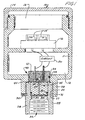
- Figure 1 is a sectional view through a typical transmitter housing having a plug and sensor arrangement made according to the present invention;
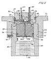
- Figure 2 is an enlarged vertical sectional view of the plug and sensor used in the transmitter housing of Figure 1; and
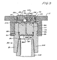
- Figure 3 is a sectional view of a modified plug made according to the present invention.
-
- Atypical transmitter housing illustrated generally at 10 includes a body 11 having a
first circuit compartment 12, and aterminal block compartment 13. The terminal block compartment has a threadedcover 14 thereon for access toterminal screws 15 mounted on the terminal block 16. - A circuit is represented at 20 in the circuit compartment The circuit can be conventional, as now used with two-wire transmitters that are well known in the art.
- The transmitter housing has a hole or opening 22 defined in a wall thereof leading to the circuit compartment, and
hole 22 leads to the interior of asleeve 23. The interior surface ofsleeve 23 is threaded as at 24 for receiving aplug assembly 25, which includes a sleeve-like fitting 26 that has a threadedneck 27 mating with interior dass 1threads 24 on the interior of thesleeve 23. Thethreads 24 ofsleeve 23 and the threadedneck 27 ofplug 26 are class 1 threads to provide for a close fit to insure that there is a flame arresting path defined along this juncture. These threads are expensive to make, so the number of places they are used should be minimized. Aroll pin 30 is positioned through a radial opening in thesleeve 23 to extend into agroove 31 in the sleeve-like fitting 26 to provide for an anti-rotation stop for theplug assembly 25. - The sleeve-
like fitting 26 has a smaller diameter inner end that fits within the opening 22, and has an internal passageway indicated generally at 32 which includes apassageway portion 33 above acapture ring 34 defined about midway along the length of the sleeve-like fitting 26. Theinterior passageway portion 33 is of size to receive anisolator block 35, which has an O-ring seal 36 around the periphery thereof that seals on the interior ofpassageway portion 33. The interior surface offitting 26 which formspassageway 33 is very precisely machined, and the outer surface of theisolator block 35 Is also precisely machined to leave a maximum space of .004 inches between the surface ofplug 26 which forms thepassageway 33 and the outer surface of theisolator block 35. This spacing also provides a flame quenching path of a shape that is of sufficient length and appropriate clearance to arrest or quench a flame which may be venting from thecircuit compartment 12 to the exterior. - As can be seen in figure 1 the
isolator block 35 forms part of asensor assembly 40. Theisolator block 35 is fixed to asensor support block 41 with a suitable peripheral weld indicated at 42. Thesensor support block 41 is cylindrical and fits into the opening 22 in the housing wall, and has an O-ring seal 43 around the periphery at approximately its midsection to seal the opening 22 with respect to thecircuit compartment 12. Thesupport block 41 is formed with a suitable recess indicated at 44 on an end thereof facing theisolator block 35. Recess 44 has a support surface that supports a silicon chip diaphragmtype pressure sensor 45.Suitable mounting material 46 can be used for mounting a sensor base to the surface ofsensor support block 41. The sensor base has a diaphragm section 47 supported thereon to provide for the sensing of pressure present in the recess orchamber 44. - A
recess 50 is provided behind the base of thesilicon chip 45 and is open to asmall diameter hole 51 that is a maximum of 0.381 mm (.015 inches) in diameter, and which extends radially outward to an interspace indicated at 52 between the outer periphery of thesensor support block 41 and the surface ofhole 22. Theinterspace 52 is open to thethreads 24 retaining thefitting 26. - The
sensor support block 41 has a pair ofholes 53 that are used for mounting a lead 57 and anoil fill tube 55 which acts as a lead. Theisolator block 35 has aflexible isolator diaphragm 35A welded at its periphery to cover the end surface that is facingcapture ring 34, and the inner side of theisolator diaphragm 35A opens to a small diameter (0.381mm, .015 inches)isolator fluid passageway 35B that leads, in turn, to the cavity orchamber 44. -
Chamber 44,passageway 35B and the underside of thediaphragm 35A are filled with a suitable silicone oil through ametallic tube 55, which fits into one of theholes 53 and is held in the hole with a suitable material indicated at 56. Thetube 55 is metal, and has a hollow interior through which oil can be filled for filling theisolation passageway 35B, the underside of thediaphragm 35A and thechamber 44 with silicone oil, after which the end of the tube is sealed or closed to hold the oil in place. Tube 55 is connected with a suitable lead to one side of the sensing diaphragm 47 and also used to carry electrical signals to the circuit 20. Theother hole 53 has a suitable electrical lead 57 therein and which is held in place with amaterial 58, such as some type of insulating material. The lead 57 is also connected to the circuit 20 and to the sensor. The opening orhole 51 actually bypasses theopenings 53, because it does not open tochamber 44 although in figure 2 it is shown in section along with theadjacent opening 53 for convenience. -
Small diameter openings - The
sensor assembly 40 is suitably welded to theisolator block 35 as at 42, as explained, and is also welded to the sleeve-like fitting 26 with a weld 41A, to form theplug assembly 25 that can be mounted in place when the sleeve-like fitting 26 is threaded into the interior of thehousing sleeve 23. Theblock 41 has a shoulder surface 41B that seats on the end surface of thefitting 26. The shoulder 41B forms a short neck 41C that fits into thebore portion 33. The weld 42 is around the periphery of the neck 41C. - The
lower portion 60 of the sleeve-like fitting 26 has a standard pipe tap thread on the interior to receive a pressure fitting from a process pressure line or source. The outer surface on the portion of the sleeve-like fitting 26 that extends out ofsleeve 23 can be shaped into a hexagon so that it can be removed and installed with a wrench. - Since a transmitter may be used in atmospheres that have flammable mixtures, and has areas that are hard to protect adequately, such as the sensor mounting chamber, adequate flame quenching has been a problem. The
isolator block 35 andisolator diaphragm 35A have to be exposed to the process fluid pressure for sensing and an adequate flame quenching path has to be provided even if theisolator diaphragm 35A, for example, has been damaged or ruptured, or the welds 42 and 41A have failed. Such protection is provided in the present device in a low cost manner. - The spacing of 0.1016mm (.004 inch) between the isolator plug or block 35 and the
bore 33, along the plug length of about 1/2 inches provides a path of a shape to cool the combusted gases and quench a flame travelling from the interior of the transmitter housing to the exterior down the venting passageway before the flame reaches the atmosphere. Additionally, thepassageway 35B provides a flame quenching path because of its small diameter and an adequate length (as shown in the range of 13.2mm (.52 inches) so that if thediaphragm 35A ruptures, and the isolator fluid Is lost and a spark ignites a flame in thesensor chamber 44, the flame would be cooled and quenched before it reached the exterior end of thepassageway 35B. -
Passageway 51 is also of suitable size to provide for venting of thechamber 50 on the back side of thepressure sensor 45, through theinterspace 52 and then through thethreads 24, which are class 1 flame quenching threads, to the atmosphere. Threads are especially desirable as flame quenching paths because they provide a large cross sectional area for venting and resist plugging with contaminants. - If the weld 42 should fail, the
isolator block 35 conceivably could be blown out of the central opening orpassageway 32 of the sleeve-like fitting 26 upon ignition of a flame inchamber 44, but thecapture ring 34 is provided for insuring that the 0.1016mm (.004 inch) clearance between theblock 35 and the bore portion opening 33 will not be lost even if the weld 42 falls. Thecapture ring 34 will hold the isolator block in safety position, even upon failure of a weld. - The
bore portion 60 comprises a threaded connector that can be coupled to a pressure line along the central axis of the bore oropening 22, and the bore on the interior of thesleeve 23, which are coaxial. The pressure from the line connected to the sleeve-like fitting 26 provides pressure to theIsolator diaphragm 35A so that process line pressure is coupled to thesensor 45 due to the filling of noncompressible fluid in thepassageway 35B formed in theisolator block 35. -
Sensor mounting block 41 forms a part of theplug assembly 25, and has a peripheral surface that forms theinterspace 52 with a shape that cools flames and isolates thesensor cavity 50 and thecircuit chamber 12 from the atmosphere in combination with the class 1threads 24. Thesmall diameter passageway 51 further provides for flame isolation between theatmospheric pressure cavity 50 and the atmosphere through theinterspace 52 andthreads 24. - In Figure 3, a modified form of the invention is illustrated, having the same capabilities of flame arresting as in the first form of the invention. A portion of the transmitter housing indicated at 11 Is again shown, and in this form of the invention, the
opening 22 is provided, along withsleeve 23 having theInterlor threads 24. The transmitter, of course, would have the circuit in thecircuit compartment 12 as previously explained. - A
plug assembly 80 includes a sleeve-like fitting 81 that also is provided with a threaded exterior end indicated at 82, that mates with thethreads 24 on the interior of thesleeve 23 so that theplug assembly 80 can be threaded into thesleeve 23 or removed as desired. Aroll pin 30 is also provided for fitting into aslot 83 to prevent the sleeve-like fitting 81 from unthreading. - An
interior passageway 84 of the fitting 81 has a precisely formed bore portion 85 into which anIsolator block 86 is placed. The spacing between the outer surface of theisolator block 86 and the interior surface of the bore portion 85 is kept in the range of 0.1016mm (.004 inches)(diameter differences), and having a path length of in the range of 12.7mm (1/2 inch). - A
capture ring 87 is provided to the lower edge of the bore portion 85, and it has a smaller internal diameter than the diameter of theisolator block 86. - The
isolator block 86 has an thinflexible Isolation diaphragm 86A at the end thereof adjacent thering 87, which encloses a passageway 86B that is filled with isolator fluid as well as being a flame arresting passageway as will be explained. Theisolator block 86 has an O-ring 88 thereon for sealing it relative to the surface of the bore portion 85. - A process
pressure sensor assembly 89 includes a pressuresensor support block 90 which has a recess 91 at an end thereof facing theisolator block 86. Thesensor support block 90, which is part ofsensor assembly 89, is welded as at 91A to theisolator block 86 to form an assembly and seal the recess 91 around the periphery. The recess 91 is a sensor mounting recess, and a suitable pressure sensor 92 is mounted therein on an inner surface. The recess 91 forms a chamber that is open to the passageway 86B. The underside of thediaphragm 86A, the recess 91 and passageway 86B are filled with a silicone oil or other suitable noncompressible fluid. An oil fill passageway indicated at 94 is provided and opens to the recess 91. A ball closure valve 95 held in place with asuitable plug 96 closes the passageway 94 after filling fluid into the sensor isolator chambers and passageways. - An atmospheric pressure chamber 98 is provided on the opposite side of the sensor diaphragm portion 110 from the
isolator block 86. Chamber 98 is connected with a small diameterflame arresting passageway 100 to aninterspace 101 between the innersurface defining hole 22 and the outer periphery of thesensor mounting block 90. Thisinterspace 101 is precisely sized with about 0.1016mm (.004 inches) total diameter difference, for forming a flame quenching path to atmosphere throughthreads 24. Thehole 100 is formed of suitable size and length to also form a flame quenching path leading to the interspace. It should also be noted that thesensor support block 90 is welded to the sleeve-like fitting 81 with asuitable weld 102. - A lead 103 is attached to the sensor 92 and passes outwardly through a suitable passageway 104 in this form of the invention. The sensor 92 is supported on its edges on the inner end of recess 91 and the diaphragm 110 will deflect under differences in pressure acting through the
isolator diaphragm 86A with respect to atmosphere pressure in chamber 98. - A suitable pressure line connector or fitting 105 is threaded into the interior of a threaded
portion 106 of the sleeve-like fitting 81, using conventional threads to provide process fluid pressure to thediaphragm 86A, and thus through passageway 86B and the noncompressible fluid in the chamber 91 to the diaphragm portion 110 of the pressure sensor 92. An O-ring 112 seals the outer surface of thesensor block 90 with respect to the surface of the bore oropening 22. - In each instance, again, the sensor recess or cavity 91, where ignition of combustible gases can occur is connected through flame arresting paths in all outlet paths leading toward the ambient atmosphere, which may be combustible. This includes the conventional class 1
threads 24 which have a long path length and low clearance, the annular space between the exterior surface of theisolator block 86 and the surface of bore portion 85, which has a clearance of about 0.1016mm (.004 inches) and a path length of about 12.7mm (1/2 inch). This passageway would be open to atmosphere if the weld 91A failed, and flame from chamber 91 was present and was travelling toward the atmosphere. Thecapture ring 87 will hold theisolator block 86 within bore portion 85 so that the flame arresting path is maintained regardless of failure of such weld. - The passageway 86B, that is the isolator fluid passageway leading to recess 91, has a small diameter (0.381mm, .015 in.) and a sufficient length so that it will quench flames that tend to travel to atmosphere through such opening 86B if there is a failure of the
diaphragm 86A and discharge and loss of the isolating fluid. - The atmospheric chamber 98 is connected to atmosphere through a
flame quenching passageway 100 which has a shape (0.381mm, .015 in. diameter) sufficient for causing flame quenching, as does theinterspace 101 between the periphery of thesensor plug 90 and thebore 22. - Thus by selecting the paths through the
isolator 86 for presenting process fluid pressure to the sensor to have a configuration that provides flame quenching characteristics, and also selecting the paths that provide atmospheric pressure to such sensor to have flame quenching configurations or shapes, the transmitter is made to be intrinsically safe. The conventional threads on the cap shown at 14 for the transmitter housing also provide flame quenching paths. Flame quenching shapes also can be made by filling wider passageways with sintered or porous material. - The assembly shown provides for a low cost, safe sensor mounting plug without having a large number of high cost thread interfaces, the flame quenching paths are maintained in case of a failure of a weld or an isolator diaphragm with the present configuration to make the assembly intrinsically safe.
- Although the present invention has been described with reference to preferred embodiments, workers skilled in the art will recognize that changes may be made in form and detail without departing from the terms of the claims.
Claims (5)
- A transmitter (10) providing an output indicating a pressure difference between a line and an atmosphere outside the transmitter, comprising:a housing (11) forming a wall around an axis of a hole (22) extending into a cavity (12) formed in the housing;a circuit (20) in the cavity (12) controlling the output;a sensor (45, 92) coupled to the circuit (20) for sensing the pressure difference; anda plug (40, 89) in the hole (22) having a sensor cavity (44, 91) holding the sensor (45, 92), a fitting (26, 81) couplable to the line along the axis at a distal end of the plug (40, 89), and a diaphragm (35A, 86A) therein coupling line pressure to the sensor (45, 92) via a liquid in a first passageway (35B, 86B) formed in the plug, the first passageway (35B, 86B) having a shape which flame-isolates the sensor (45, 92) from the line and said fitting being a sleeve-like fitting having a bore (33, 85), a first block (35, 86) mounted in said bore (33, 85) forming part of said plug (40, 89) the first block (35, 86) closing the sensor cavity in a second block (41, 90) and having the diaphragm (35A, 86A) mounted thereon and the first passageway (35B, 36B), therein the space between the first block (35, 86) and the bore (33, 85) having a shape which flame-isolates from the line, the bore (33, 85) further including a capture ring (34, 87) between the first block (35, 86) and the process fluid to ensure that the first block (35, 86) remains in the bore (33, 85) if the first block (35, 86) is separated from the second block (41, 90) and no longer closes the sensor cavity (12).
- The transmitter of claim 1 wherein the plug (40, 89) has a peripheral surface in the hole (22) adjacent the wall forming an interspace (52) having a shape which flame-isolates the circuit (20) from the atmosphere.
- The transmitter of claim 2 wherein the plug (40, 89) has a second passageway (51, 100) coupling the sensor (45, 92) to the atmosphere, the second passageway (51, 100) being formed in a shape which flame-isolates the sensor from the atmosphere.
- The transmitter of claim 3 wherein the second passageway (51, 100) couples to the atmosphere via the interspace (52).
- The transmitter of claim 1 wherein the fitting has an end surface and the second block (41, 90) has a shoulder (41B) defined thereon forming a neck which fits into the bore (33, 86), and the shoulder fitting on the end surface.
Applications Claiming Priority (4)
| Application Number | Priority Date | Filing Date | Title |
|---|---|---|---|
| US07/409,927 US4970898A (en) | 1989-09-20 | 1989-09-20 | Pressure transmitter with flame isolating plug |
| US409927 | 1989-09-20 | ||
| PCT/US1990/004280 WO1991004475A1 (en) | 1989-09-20 | 1990-07-31 | Pressure transmitter with flame isolating plug |
| SG1995900281A SG28195G (en) | 1989-09-20 | 1995-02-17 | Pressure transmitter with flame isolating plug |
Publications (4)
| Publication Number | Publication Date |
|---|---|
| EP0493397A1 EP0493397A1 (en) | 1992-07-08 |
| EP0493397A4 EP0493397A4 (en) | 1992-09-16 |
| EP0493397B1 EP0493397B1 (en) | 1994-12-21 |
| EP0493397B2 true EP0493397B2 (en) | 2004-06-16 |
Family
ID=73002443
Family Applications (1)
| Application Number | Title | Priority Date | Filing Date |
|---|---|---|---|
| EP90912186A Expired - Lifetime EP0493397B2 (en) | 1989-09-20 | 1990-07-31 | Pressure transmitter with flame isolating plug |
Country Status (20)
| Country | Link |
|---|---|
| US (1) | US4970898A (en) |
| EP (1) | EP0493397B2 (en) |
| JP (1) | JP2804173B2 (en) |
| KR (1) | KR0165561B1 (en) |
| CN (1) | CN1021847C (en) |
| AT (1) | ATE116059T1 (en) |
| AU (1) | AU652721B2 (en) |
| BR (1) | BR9007667A (en) |
| CA (1) | CA2059644A1 (en) |
| DD (1) | DD295501A5 (en) |
| DE (1) | DE69015367T3 (en) |
| DK (1) | DK0493397T3 (en) |
| ES (1) | ES2066214T3 (en) |
| HK (1) | HK86295A (en) |
| HU (2) | HU9200949D0 (en) |
| MX (1) | MX172199B (en) |
| PL (1) | PL162336B1 (en) |
| RU (1) | RU2054166C1 (en) |
| SG (1) | SG28195G (en) |
| WO (1) | WO1991004475A1 (en) |
Families Citing this family (86)
| Publication number | Priority date | Publication date | Assignee | Title |
|---|---|---|---|---|
| JP3133311B2 (en) * | 1990-04-24 | 2001-02-05 | ヤマハ発動機株式会社 | Fuel injection two-stroke engine |
| US5402683A (en) * | 1991-10-30 | 1995-04-04 | Toyota Jidosha Kabushiki Kaisha | Built-in amplifier-type combustion pressure sensor and manufacturing method thereof |
| US5287746A (en) * | 1992-04-14 | 1994-02-22 | Rosemount Inc. | Modular transmitter with flame arresting header |
| IL106790A (en) * | 1992-09-01 | 1996-08-04 | Rosemount Inc | Pedestal mount capacitive pressure sensor and a process of manufacturing same |
| US5439021A (en) * | 1992-09-09 | 1995-08-08 | Fisher Controls International, Inc. | Electro-pneumatic converter |
| DE4244460C1 (en) * | 1992-12-23 | 1994-04-14 | Siemens Ag | Pressure transmitter |
| DE4244459C1 (en) * | 1992-12-23 | 1994-05-11 | Siemens Ag | Pressure transmitter |
| EP0658754B1 (en) * | 1993-12-14 | 1997-07-30 | ENVEC Mess- und Regeltechnik GmbH + Co. | Pressure measuring arrangement |
| US5583294A (en) * | 1994-08-22 | 1996-12-10 | The Foxboro Company | Differential pressure transmitter having an integral flame arresting body and overrange diaphragm |
| US5637802A (en) * | 1995-02-28 | 1997-06-10 | Rosemount Inc. | Capacitive pressure sensor for a pressure transmitted where electric field emanates substantially from back sides of plates |
| WO1996034265A1 (en) * | 1995-04-28 | 1996-10-31 | Rosemount Inc. | Mounting assembly for a pressure transmitter |
| DE69629024T2 (en) * | 1995-04-28 | 2004-04-22 | Rosemount Inc., Eden Prairie | PRESSURE CONVERTER WITH MOUNTING ARRANGEMENT WITH HIGH PRESSURE INSULATOR |
| US5824909A (en) * | 1995-08-04 | 1998-10-20 | Ifm Electronic Gmbh | Pressure measuring sensor and apparatus having a seal between a housing and a pressure measuring cell |
| US5744726A (en) * | 1997-02-25 | 1998-04-28 | Honeywell Inc. | Pressure sensor with reduced dead space achieved through an insert member with a surface groove |
| US5808205A (en) * | 1997-04-01 | 1998-09-15 | Rosemount Inc. | Eccentric capacitive pressure sensor |
| KR100313995B1 (en) * | 1997-12-02 | 2001-12-28 | 구자홍 | Device for preventing frost in free piston stirling cooler |
| US6046667A (en) * | 1997-12-23 | 2000-04-04 | Honeywell Inc. | Pressure transducer with porous material for media isolation |
| US5948988A (en) * | 1998-05-27 | 1999-09-07 | Honeywell Inc | Pressure transducer with flame arrester |
| US6571132B1 (en) | 1999-09-28 | 2003-05-27 | Rosemount Inc. | Component type adaptation in a transducer assembly |
| US6765968B1 (en) | 1999-09-28 | 2004-07-20 | Rosemount Inc. | Process transmitter with local databus |
| US7134354B2 (en) | 1999-09-28 | 2006-11-14 | Rosemount Inc. | Display for process transmitter |
| JP3798693B2 (en) | 1999-09-28 | 2006-07-19 | ローズマウント インコーポレイテッド | Perimeter-sealed instrument loop adapter |
| US6487912B1 (en) * | 1999-09-28 | 2002-12-03 | Rosemount Inc. | Preinstallation of a pressure sensor module |
| US6484107B1 (en) | 1999-09-28 | 2002-11-19 | Rosemount Inc. | Selectable on-off logic modes for a sensor module |
| US6510740B1 (en) | 1999-09-28 | 2003-01-28 | Rosemount Inc. | Thermal management in a pressure transmitter |
| US6546805B2 (en) * | 2000-03-07 | 2003-04-15 | Rosemount Inc. | Process fluid transmitter with an environmentally sealed service block |
| US6662662B1 (en) | 2000-05-04 | 2003-12-16 | Rosemount, Inc. | Pressure transmitter with improved isolator system |
| US6504489B1 (en) | 2000-05-15 | 2003-01-07 | Rosemount Inc. | Process control transmitter having an externally accessible DC circuit common |
| US6480131B1 (en) | 2000-08-10 | 2002-11-12 | Rosemount Inc. | Multiple die industrial process control transmitter |
| DE10107813A1 (en) | 2001-02-20 | 2002-09-05 | Bosch Gmbh Robert | Pressure sensor module |
| US6516672B2 (en) | 2001-05-21 | 2003-02-11 | Rosemount Inc. | Sigma-delta analog to digital converter for capacitive pressure sensor and process transmitter |
| DE10131405A1 (en) * | 2001-06-28 | 2003-03-13 | Endress & Hauser Gmbh & Co Kg | Predictive corrosion monitoring device |
| US6684711B2 (en) | 2001-08-23 | 2004-02-03 | Rosemount Inc. | Three-phase excitation circuit for compensated capacitor industrial process control transmitters |
| US6647794B1 (en) | 2002-05-06 | 2003-11-18 | Rosemount Inc. | Absolute pressure sensor |
| US7773715B2 (en) | 2002-09-06 | 2010-08-10 | Rosemount Inc. | Two wire transmitter with isolated can output |
| US7109883B2 (en) | 2002-09-06 | 2006-09-19 | Rosemount Inc. | Low power physical layer for a bus in an industrial transmitter |
| US6715360B1 (en) * | 2003-02-19 | 2004-04-06 | Fisher Controls International, Llc | Gauge pressure sensor for hazardous applications |
| DE10314920A1 (en) * | 2003-04-01 | 2004-10-14 | Endress + Hauser Gmbh + Co. Kg | Pressure transducer with flame arrestor |
| DE10316033A1 (en) * | 2003-04-07 | 2004-10-21 | Endress + Hauser Gmbh + Co. Kg | Relativdruckmeßumformer |
| US7258021B2 (en) * | 2004-06-25 | 2007-08-21 | Rosemount Inc. | Process transmitter isolation assembly |
| US7373831B2 (en) * | 2004-06-25 | 2008-05-20 | Rosemount Inc. | High temperature pressure transmitter assembly |
| US7036381B2 (en) * | 2004-06-25 | 2006-05-02 | Rosemount Inc. | High temperature pressure transmitter assembly |
| CN100416250C (en) * | 2004-12-29 | 2008-09-03 | 上海自动化仪表股份有限公司 | Miniaturized Smart Differential Pressure/Pressure Transmitter |
| DE102005011973B4 (en) * | 2005-03-13 | 2012-04-19 | Endress + Hauser Gmbh + Co. Kg | sensor module |
| US7525419B2 (en) | 2006-01-30 | 2009-04-28 | Rosemount Inc. | Transmitter with removable local operator interface |
| US7458275B2 (en) * | 2007-03-15 | 2008-12-02 | Rosemount Inc. | Welded header for pressure transmitter |
| DE102007052395B4 (en) * | 2007-10-31 | 2009-09-10 | Kg Transmitter Components Gmbh | Pressure transmitter, method for monitoring the condition of a pressure transducer and pressure sensor |
| DE102007056844A1 (en) | 2007-11-23 | 2009-06-10 | Endress + Hauser Gmbh + Co. Kg | Membrane bed for pressure transmission device of e.g. differential pressure transducer, has surface with spiral outline that serves as embossing pattern for flexible metallic and embossed membranes, where outline is obtained by die sinking |
| US7497123B1 (en) | 2007-12-18 | 2009-03-03 | Rosemount Inc. | Direct mount for pressure transmitter with thermal management |
| US7681456B2 (en) * | 2008-06-20 | 2010-03-23 | Rosemount Inc. | Field device including a capillary tube having a non-cylindrical lumen |
| US7992441B2 (en) * | 2008-07-31 | 2011-08-09 | Sensata Technologies, Inc. | Pressure sensor for measuring pressure in a medium |
| US8387463B2 (en) * | 2008-10-06 | 2013-03-05 | Rosemount Inc. | Pressure-based diagnostic system for process transmitter |
| US8371175B2 (en) * | 2009-10-01 | 2013-02-12 | Rosemount Inc. | Pressure transmitter with pressure sensor mount |
| AU2010313245B2 (en) * | 2009-10-30 | 2014-10-23 | Msa Technology, Llc | Combustible gas sensors including integral support structures and combustible gas sensor with multiple active elements |
| US8960320B2 (en) * | 2009-11-12 | 2015-02-24 | Fisher Controls International Llc | Inline plug flame arrestors |
| EP2511684A4 (en) * | 2009-12-09 | 2017-08-30 | Kabushiki Kaisha Saginomiya Seisakusho | Structure for connection between pressure sensing section of pressure sensitive device and female threaded coupling |
| PL2520860T3 (en) * | 2009-12-30 | 2017-12-29 | Changzheng Engineering Co., Ltd. | Flame detecting device |
| US8334788B2 (en) | 2010-03-04 | 2012-12-18 | Rosemount Inc. | Process variable transmitter with display |
| RU2426080C1 (en) * | 2010-04-30 | 2011-08-10 | Государственное образовательное учреждение высшего профессионального образования "Национальный исследовательский Томский политехнический университет" | Method of measuring pressure in fluid transfer pipeline and device to this end |
| US8485040B2 (en) * | 2011-03-14 | 2013-07-16 | Rosemount Inc. | Flame arrestor for process transmitter |
| EP2511685B1 (en) * | 2011-04-13 | 2017-07-12 | VEGA Grieshaber KG | Measuring cell with a housing for holding a sensor, in particular a pressure transducer |
| US8863580B2 (en) * | 2011-05-05 | 2014-10-21 | Rosemount Inc. | Process fluid pressure transmitter with replaceable atmospheric vent filter |
| US8671766B2 (en) * | 2011-05-19 | 2014-03-18 | Infineon Technologies Ag | Integrated pressure sensor seal |
| KR101200170B1 (en) | 2012-07-09 | 2012-11-13 | 한국수력원자력 주식회사 | High temperature pressure transmitter system |
| US9410976B2 (en) * | 2012-10-17 | 2016-08-09 | Rosemount Analytical Inc. | Process analytic instrument with encapsulated flame-quenching connection |
| US9329061B2 (en) * | 2013-02-28 | 2016-05-03 | Rosemount Inc. | Reduced-stress coupling for industrial process transmitter housing |
| JP5934727B2 (en) * | 2013-03-13 | 2016-06-15 | 日本特殊陶業株式会社 | Gas sensor |
| US9607596B2 (en) * | 2013-05-06 | 2017-03-28 | Viatran Corporation | Pressure transducer |
| CN103353371B (en) * | 2013-06-20 | 2016-01-20 | 重庆市伟岸测器制造股份有限公司 | Solid particle level measurement pressure transmitter |
| US9442031B2 (en) | 2013-06-28 | 2016-09-13 | Rosemount Inc. | High integrity process fluid pressure probe |
| WO2015006977A1 (en) * | 2013-07-19 | 2015-01-22 | Rosemount Inc. | Pressure transmitter having an isolation assembly with a two-piece isolator plug |
| RU2539405C1 (en) * | 2013-08-20 | 2015-01-20 | Владислав Владимирович Ефимов | Pressure gauge fitting with lock mechanism |
| US9459170B2 (en) * | 2013-09-26 | 2016-10-04 | Rosemount Inc. | Process fluid pressure sensing assembly for pressure transmitters subjected to high working pressure |
| US9261425B2 (en) * | 2014-01-02 | 2016-02-16 | Rosemount Aerospace Inc. | High temperature pressure sensor |
| US9493133B2 (en) * | 2014-05-20 | 2016-11-15 | Ford Global Technologies, Llc | Fastening and sensing apparatus |
| US9638600B2 (en) | 2014-09-30 | 2017-05-02 | Rosemount Inc. | Electrical interconnect for pressure sensor in a process variable transmitter |
| US10209154B2 (en) * | 2015-03-30 | 2019-02-19 | Rosemount Inc. | In-line process fluid pressure transmitter for high pressure applications |
| US10385879B2 (en) * | 2016-06-27 | 2019-08-20 | Tescom Corporation | Explosion resistant electro-pneumatic controller |
| CN108240886A (en) * | 2016-12-26 | 2018-07-03 | 天津市科瑞燃气设备有限公司 | A kind of gaseous-pressure indicator |
| US20180259413A1 (en) * | 2017-03-10 | 2018-09-13 | Honeywell International Inc. | Pressure sensor having coplanar meter body with sensor overpressure protection |
| WO2019041122A1 (en) * | 2017-08-29 | 2019-03-07 | Rosemount Inc. | Process transmitter having a rotatable coupling |
| JP2021517969A (en) | 2018-05-17 | 2021-07-29 | ローズマウント インコーポレイテッド | Measuring element and measuring device equipped with it |
| US11262771B2 (en) * | 2019-09-23 | 2022-03-01 | Rosemount Inc. | High pressure capsule and header for process fluid pressure transmitter |
| WO2022128402A1 (en) * | 2020-12-14 | 2022-06-23 | Endress+Hauser SE+Co. KG | Pressure sensor for determining a relative pressure |
| CN115752874A (en) * | 2022-11-01 | 2023-03-07 | 厦门乃尔电子有限公司 | Fire-resistant pressure sensor |
| DE102024130105A1 (en) * | 2024-10-16 | 2026-04-16 | Endress+Hauser SE+Co. KG | Pressure sensor for determining and/or monitoring the initial pressure of a medium |
Citations (1)
| Publication number | Priority date | Publication date | Assignee | Title |
|---|---|---|---|---|
| DD214927A1 (en) † | 1983-05-03 | 1984-10-24 | Teltov Geraete Regler | RECORDING DEVICE FOR ELECTROMECHANICAL SEMICONDUCTOR MEASURING ELEMENTS |
Family Cites Families (15)
| Publication number | Priority date | Publication date | Assignee | Title |
|---|---|---|---|---|
| DE688097C (en) * | 1935-02-14 | 1940-02-12 | Rudolf Haas Dr Ing | Membrane pressure gauge |
| US2458086A (en) * | 1946-05-09 | 1949-01-04 | Charles W Macmillan | Engine combustion regulating device |
| US3242448A (en) * | 1962-05-03 | 1966-03-22 | Standard Controls Inc | Pressure transducer |
| US3793885A (en) * | 1972-09-05 | 1974-02-26 | Rosemount Inc | Diaphrgam construction for differential pressure transducer |
| US4068206A (en) * | 1976-06-25 | 1978-01-10 | Midland-Ross Corporation | Pressure-sensing semiconductor transducer |
| US4227418A (en) * | 1979-09-24 | 1980-10-14 | Fischer & Porter Company | Capacitive pressure transducer |
| US4370890A (en) * | 1980-10-06 | 1983-02-01 | Rosemount Inc. | Capacitive pressure transducer with isolated sensing diaphragm |
| JPS5887880A (en) * | 1981-11-20 | 1983-05-25 | Hitachi Ltd | Semiconductor diaphragm sensor |
| DE3313259A1 (en) * | 1983-04-13 | 1984-10-25 | Ermeto Armaturen Gmbh, 4800 Bielefeld | SENSOR |
| DE3313261A1 (en) * | 1983-04-13 | 1984-10-25 | Ermeto Armaturen Gmbh, 4800 Bielefeld | SENSOR |
| US4586018A (en) * | 1983-09-19 | 1986-04-29 | Ford Motor Company | Combustion pressure sensor |
| IT1185212B (en) * | 1985-07-09 | 1987-11-04 | Kent Tieghi Spa | PRESSURE TRANSMITTER OF FLUIDS FOR POTENTIALLY EXPLOSIVE ATMOSPHERES |
| ATE42637T1 (en) * | 1985-09-11 | 1989-05-15 | Kunz Manfred | PRESSURE SENSOR. |
| JPH01301134A (en) * | 1988-05-30 | 1989-12-05 | Nippon Beeles- Kk | Pressure transmitter |
| DE3838312A1 (en) * | 1988-11-11 | 1990-05-17 | Eckardt Ag | Flashback-proof valve |
-
1989
- 1989-09-20 US US07/409,927 patent/US4970898A/en not_active Expired - Lifetime
-
1990
- 1990-07-31 HU HU9200949A patent/HU9200949D0/en unknown
- 1990-07-31 AU AU61733/90A patent/AU652721B2/en not_active Ceased
- 1990-07-31 DK DK90912186.5T patent/DK0493397T3/en active
- 1990-07-31 AT AT90912186T patent/ATE116059T1/en not_active IP Right Cessation
- 1990-07-31 RU SU905011221A patent/RU2054166C1/en active
- 1990-07-31 KR KR1019920700635A patent/KR0165561B1/en not_active Expired - Fee Related
- 1990-07-31 HU HU9200949A patent/HU213193B/en not_active IP Right Cessation
- 1990-07-31 BR BR909007667A patent/BR9007667A/en not_active IP Right Cessation
- 1990-07-31 WO PCT/US1990/004280 patent/WO1991004475A1/en not_active Ceased
- 1990-07-31 CA CA002059644A patent/CA2059644A1/en not_active Abandoned
- 1990-07-31 EP EP90912186A patent/EP0493397B2/en not_active Expired - Lifetime
- 1990-07-31 ES ES90912186T patent/ES2066214T3/en not_active Expired - Lifetime
- 1990-07-31 JP JP2511633A patent/JP2804173B2/en not_active Expired - Fee Related
- 1990-07-31 DE DE69015367T patent/DE69015367T3/en not_active Expired - Fee Related
- 1990-08-24 DD DD90343630A patent/DD295501A5/en not_active IP Right Cessation
- 1990-08-29 CN CN90107348A patent/CN1021847C/en not_active Expired - Fee Related
- 1990-08-31 MX MX022185A patent/MX172199B/en unknown
- 1990-09-20 PL PL28697390A patent/PL162336B1/en unknown
-
1995
- 1995-02-17 SG SG1995900281A patent/SG28195G/en unknown
- 1995-06-01 HK HK86295A patent/HK86295A/en not_active IP Right Cessation
Patent Citations (1)
| Publication number | Priority date | Publication date | Assignee | Title |
|---|---|---|---|---|
| DD214927A1 (en) † | 1983-05-03 | 1984-10-24 | Teltov Geraete Regler | RECORDING DEVICE FOR ELECTROMECHANICAL SEMICONDUCTOR MEASURING ELEMENTS |
Non-Patent Citations (5)
| Title |
|---|
| "PTB-Bericht; 2. Sicherheitstechnische Vortragsveranstaltung über Fragen des Explosionsschutzes; Vorträge des 48. PTB-Seminars am 10.02.83"; Edition H. Steen; ISSN 0341-6739; March 1983 † |
| "Silizium-Halbleiter-Messumformer für Druck und Differenzdruck"; in a catalogue of VEB-Kombinat Automatisierungsanlagenbau; 1982 † |
| Brochure of 07.80 "Piezoresistive Sonden DB 16, 17, 26, 27 A/BZ" with corresponding † |
| Certificate of compliance PTB No. Ex-80/2142 X † |
| Löffler et al, "Piezoresistive Drucksensoren für die Automatisierungstechnik (Teil 2)" msr, Berlin 30, (1987) 7, pages 317-321 † |
Also Published As
| Publication number | Publication date |
|---|---|
| MX172199B (en) | 1993-12-07 |
| SG28195G (en) | 1995-08-18 |
| AU652721B2 (en) | 1994-09-08 |
| JPH05500106A (en) | 1993-01-14 |
| CN1021847C (en) | 1993-08-18 |
| DE69015367D1 (en) | 1995-02-02 |
| DD295501A5 (en) | 1991-10-31 |
| EP0493397A4 (en) | 1992-09-16 |
| HK86295A (en) | 1995-06-09 |
| EP0493397A1 (en) | 1992-07-08 |
| DE69015367T2 (en) | 1995-05-04 |
| HU213193B (en) | 1997-03-28 |
| PL162336B1 (en) | 1993-10-30 |
| WO1991004475A1 (en) | 1991-04-04 |
| HU9200949D0 (en) | 1992-07-28 |
| KR0165561B1 (en) | 1999-03-30 |
| CA2059644A1 (en) | 1991-03-21 |
| CN1050441A (en) | 1991-04-03 |
| ES2066214T3 (en) | 1995-03-01 |
| AU6173390A (en) | 1991-04-18 |
| DK0493397T3 (en) | 1995-03-20 |
| PL286973A1 (en) | 1991-05-20 |
| ATE116059T1 (en) | 1995-01-15 |
| US4970898A (en) | 1990-11-20 |
| RU2054166C1 (en) | 1996-02-10 |
| EP0493397B1 (en) | 1994-12-21 |
| BR9007667A (en) | 1992-06-02 |
| HUT67785A (en) | 1995-04-28 |
| DE69015367T3 (en) | 2005-02-17 |
| JP2804173B2 (en) | 1998-09-24 |
| KR920704111A (en) | 1992-12-19 |
Similar Documents
| Publication | Publication Date | Title |
|---|---|---|
| EP0493397B1 (en) | Pressure transmitter with flame isolating plug | |
| EP0636243B1 (en) | Modular transmitter with flame arresting header | |
| US4352365A (en) | Pressure vessel safety valve | |
| US5213128A (en) | Pressure/temperature-activated pressure relief valve | |
| EP1595124B1 (en) | Gauge pressure sensor hazardous applications | |
| US20110168415A1 (en) | Dispensing valve and method for dispensing a fluid under pressure | |
| EP0617811A4 (en) | Pressure relief valve with thermal trigger and movable seal plug. | |
| US7251985B2 (en) | Safety module and measuring arrangement with safety module | |
| JPS63259299A (en) | Gas-pressure regulator | |
| JPH09318416A (en) | Self-sealing type inspection hole for fluid container | |
| JP2002181298A (en) | Valve device for gas cylinder | |
| JP2002168399A (en) | Valve device for gas cylinder | |
| GB2322449A (en) | Detecting pressure changes | |
| KR200294427Y1 (en) | Safety valve for gas leakage alarm | |
| JPS6338784A (en) | Fluid temperature detecting type operating valve |
Legal Events
| Date | Code | Title | Description |
|---|---|---|---|
| PUAI | Public reference made under article 153(3) epc to a published international application that has entered the european phase |
Free format text: ORIGINAL CODE: 0009012 |
|
| 17P | Request for examination filed |
Effective date: 19920203 |
|
| AK | Designated contracting states |
Kind code of ref document: A1 Designated state(s): AT BE DE DK ES FR GB IT NL SE |
|
| A4 | Supplementary search report drawn up and despatched |
Effective date: 19920724 |
|
| AK | Designated contracting states |
Kind code of ref document: A4 Designated state(s): AT BE DE DK ES FR GB IT NL SE |
|
| 17Q | First examination report despatched |
Effective date: 19930728 |
|
| GRAA | (expected) grant |
Free format text: ORIGINAL CODE: 0009210 |
|
| AK | Designated contracting states |
Kind code of ref document: B1 Designated state(s): AT BE DE DK ES FR GB IT NL SE |
|
| PG25 | Lapsed in a contracting state [announced via postgrant information from national office to epo] |
Ref country code: FR Free format text: LAPSE BECAUSE OF NON-PAYMENT OF DUE FEES Effective date: 19941221 |
|
| REF | Corresponds to: |
Ref document number: 116059 Country of ref document: AT Date of ref document: 19950115 Kind code of ref document: T |
|
| EAL | Se: european patent in force in sweden |
Ref document number: 90912186.5 |
|
| REF | Corresponds to: |
Ref document number: 69015367 Country of ref document: DE Date of ref document: 19950202 |
|
| ET | Fr: translation filed | ||
| ITF | It: translation for a ep patent filed | ||
| REG | Reference to a national code |
Ref country code: ES Ref legal event code: FG2A Ref document number: 2066214 Country of ref document: ES Kind code of ref document: T3 |
|
| REG | Reference to a national code |
Ref country code: DK Ref legal event code: T3 |
|
| PLBI | Opposition filed |
Free format text: ORIGINAL CODE: 0009260 |
|
| 26 | Opposition filed |
Opponent name: ENDRESS + HAUSER GMBH + CO. Effective date: 19950831 |
|
| NLR1 | Nl: opposition has been filed with the epo |
Opponent name: ENDRESS Opponent name: HAUSER GMBH |
|
| PLBF | Reply of patent proprietor to notice(s) of opposition |
Free format text: ORIGINAL CODE: EPIDOS OBSO |
|
| PLBF | Reply of patent proprietor to notice(s) of opposition |
Free format text: ORIGINAL CODE: EPIDOS OBSO |
|
| PLBF | Reply of patent proprietor to notice(s) of opposition |
Free format text: ORIGINAL CODE: EPIDOS OBSO |
|
| PLBO | Opposition rejected |
Free format text: ORIGINAL CODE: EPIDOS REJO |
|
| APAC | Appeal dossier modified |
Free format text: ORIGINAL CODE: EPIDOS NOAPO |
|
| APAE | Appeal reference modified |
Free format text: ORIGINAL CODE: EPIDOS REFNO |
|
| APAC | Appeal dossier modified |
Free format text: ORIGINAL CODE: EPIDOS NOAPO |
|
| PLBQ | Unpublished change to opponent data |
Free format text: ORIGINAL CODE: EPIDOS OPPO |
|
| PLAB | Opposition data, opponent's data or that of the opponent's representative modified |
Free format text: ORIGINAL CODE: 0009299OPPO |
|
| R26 | Opposition filed (corrected) |
Opponent name: ENDRESS + HAUSER GMBH + CO. Effective date: 19950831 |
|
| NLR1 | Nl: opposition has been filed with the epo |
Opponent name: ENDRESS Opponent name: HAUSER GMBH |
|
| APCC | Communication from the board of appeal sent |
Free format text: ORIGINAL CODE: EPIDOS OBAPO |
|
| APCC | Communication from the board of appeal sent |
Free format text: ORIGINAL CODE: EPIDOS OBAPO |
|
| APAC | Appeal dossier modified |
Free format text: ORIGINAL CODE: EPIDOS NOAPO |
|
| PGFP | Annual fee paid to national office [announced via postgrant information from national office to epo] |
Ref country code: AT Payment date: 19990820 Year of fee payment: 10 Ref country code: FR Payment date: 19990820 Year of fee payment: 10 Ref country code: SE Payment date: 19990820 Year of fee payment: 10 |
|
| PGFP | Annual fee paid to national office [announced via postgrant information from national office to epo] |
Ref country code: DK Payment date: 19990823 Year of fee payment: 10 Ref country code: NL Payment date: 19990823 Year of fee payment: 10 |
|
| PGFP | Annual fee paid to national office [announced via postgrant information from national office to epo] |
Ref country code: ES Payment date: 19990830 Year of fee payment: 10 |
|
| PGFP | Annual fee paid to national office [announced via postgrant information from national office to epo] |
Ref country code: BE Payment date: 19990910 Year of fee payment: 10 |
|
| PG25 | Lapsed in a contracting state [announced via postgrant information from national office to epo] |
Ref country code: DK Free format text: LAPSE BECAUSE OF NON-PAYMENT OF DUE FEES Effective date: 20000731 Ref country code: BE Free format text: LAPSE BECAUSE OF NON-PAYMENT OF DUE FEES Effective date: 20000731 Ref country code: AT Free format text: LAPSE BECAUSE OF NON-PAYMENT OF DUE FEES Effective date: 20000731 |
|
| PG25 | Lapsed in a contracting state [announced via postgrant information from national office to epo] |
Ref country code: ES Free format text: LAPSE BECAUSE OF NON-PAYMENT OF DUE FEES Effective date: 20000801 Ref country code: SE Free format text: LAPSE BECAUSE OF NON-PAYMENT OF DUE FEES Effective date: 20000801 |
|
| PLAW | Interlocutory decision in opposition |
Free format text: ORIGINAL CODE: EPIDOS IDOP |
|
| BERE | Be: lapsed |
Owner name: ROSEMOUNT INC. Effective date: 20000731 |
|
| PG25 | Lapsed in a contracting state [announced via postgrant information from national office to epo] |
Ref country code: NL Free format text: LAPSE BECAUSE OF NON-PAYMENT OF DUE FEES Effective date: 20010201 |
|
| REG | Reference to a national code |
Ref country code: DK Ref legal event code: EBP |
|
| APAC | Appeal dossier modified |
Free format text: ORIGINAL CODE: EPIDOS NOAPO |
|
| NLV4 | Nl: lapsed or anulled due to non-payment of the annual fee |
Effective date: 20010201 |
|
| APAE | Appeal reference modified |
Free format text: ORIGINAL CODE: EPIDOS REFNO |
|
| EUG | Se: european patent has lapsed |
Ref document number: 90912186.5 |
|
| REG | Reference to a national code |
Ref country code: FR Ref legal event code: ST |
|
| APAC | Appeal dossier modified |
Free format text: ORIGINAL CODE: EPIDOS NOAPO |
|
| REG | Reference to a national code |
Ref country code: GB Ref legal event code: IF02 |
|
| PLBQ | Unpublished change to opponent data |
Free format text: ORIGINAL CODE: EPIDOS OPPO |
|
| PLAB | Opposition data, opponent's data or that of the opponent's representative modified |
Free format text: ORIGINAL CODE: 0009299OPPO |
|
| R26 | Opposition filed (corrected) |
Opponent name: ENDRESS + HAUSER GMBH + CO. Effective date: 19950831 |
|
| APBU | Appeal procedure closed |
Free format text: ORIGINAL CODE: EPIDOSNNOA9O |
|
| REG | Reference to a national code |
Ref country code: ES Ref legal event code: FD2A Effective date: 20010810 |
|
| PUAH | Patent maintained in amended form |
Free format text: ORIGINAL CODE: 0009272 |
|
| STAA | Information on the status of an ep patent application or granted ep patent |
Free format text: STATUS: PATENT MAINTAINED AS AMENDED |
|
| 27A | Patent maintained in amended form |
Effective date: 20040616 |
|
| AK | Designated contracting states |
Kind code of ref document: B2 Designated state(s): AT BE DE DK ES FR GB IT NL SE |
|
| PGFP | Annual fee paid to national office [announced via postgrant information from national office to epo] |
Ref country code: GB Payment date: 20040728 Year of fee payment: 15 |
|
| EN | Fr: translation not filed | ||
| PG25 | Lapsed in a contracting state [announced via postgrant information from national office to epo] |
Ref country code: GB Free format text: LAPSE BECAUSE OF NON-PAYMENT OF DUE FEES Effective date: 20050731 Ref country code: IT Free format text: LAPSE BECAUSE OF NON-PAYMENT OF DUE FEES;WARNING: LAPSES OF ITALIAN PATENTS WITH EFFECTIVE DATE BEFORE 2007 MAY HAVE OCCURRED AT ANY TIME BEFORE 2007. THE CORRECT EFFECTIVE DATE MAY BE DIFFERENT FROM THE ONE RECORDED. Effective date: 20050731 |
|
| APAH | Appeal reference modified |
Free format text: ORIGINAL CODE: EPIDOSCREFNO |
|
| GBPC | Gb: european patent ceased through non-payment of renewal fee |
Effective date: 20050731 |
|
| PGFP | Annual fee paid to national office [announced via postgrant information from national office to epo] |
Ref country code: DE Payment date: 20080829 Year of fee payment: 19 |
|
| PG25 | Lapsed in a contracting state [announced via postgrant information from national office to epo] |
Ref country code: DE Free format text: LAPSE BECAUSE OF NON-PAYMENT OF DUE FEES Effective date: 20100202 |