EP0491990B1 - Quick-assembling furniture hinge - Google Patents
Quick-assembling furniture hinge Download PDFInfo
- Publication number
- EP0491990B1 EP0491990B1 EP90125572A EP90125572A EP0491990B1 EP 0491990 B1 EP0491990 B1 EP 0491990B1 EP 90125572 A EP90125572 A EP 90125572A EP 90125572 A EP90125572 A EP 90125572A EP 0491990 B1 EP0491990 B1 EP 0491990B1
- Authority
- EP
- European Patent Office
- Prior art keywords
- base plate
- mounting element
- hinge arm
- slider
- hinge
- Prior art date
- Legal status (The legal status is an assumption and is not a legal conclusion. Google has not performed a legal analysis and makes no representation as to the accuracy of the status listed.)
- Expired - Lifetime
Links
- 230000007704 transition Effects 0.000 claims description 6
- 238000010348 incorporation Methods 0.000 abstract description 4
- 230000013011 mating Effects 0.000 description 6
- 230000008878 coupling Effects 0.000 description 1
- 238000010168 coupling process Methods 0.000 description 1
- 238000005859 coupling reaction Methods 0.000 description 1
- 230000000694 effects Effects 0.000 description 1
- 238000003780 insertion Methods 0.000 description 1
- 230000037431 insertion Effects 0.000 description 1
- 238000000034 method Methods 0.000 description 1
- 239000007787 solid Substances 0.000 description 1
Images


Classifications
-
- E—FIXED CONSTRUCTIONS
- E05—LOCKS; KEYS; WINDOW OR DOOR FITTINGS; SAFES
- E05D—HINGES OR SUSPENSION DEVICES FOR DOORS, WINDOWS OR WINGS
- E05D7/00—Hinges or pivots of special construction
- E05D7/12—Hinges or pivots of special construction to allow easy detachment of the hinge from the wing or the frame
- E05D7/123—Hinges or pivots of special construction to allow easy detachment of the hinge from the wing or the frame specially adapted for cabinets or furniture
- E05D7/125—Hinges or pivots of special construction to allow easy detachment of the hinge from the wing or the frame specially adapted for cabinets or furniture the hinge having two or more pins
-
- A—HUMAN NECESSITIES
- A47—FURNITURE; DOMESTIC ARTICLES OR APPLIANCES; COFFEE MILLS; SPICE MILLS; SUCTION CLEANERS IN GENERAL
- A47B—TABLES; DESKS; OFFICE FURNITURE; CABINETS; DRAWERS; GENERAL DETAILS OF FURNITURE
- A47B2230/00—Furniture jointing; Furniture with such jointing
- A47B2230/11—Attachment fittings mounted in blind holes
-
- E—FIXED CONSTRUCTIONS
- E05—LOCKS; KEYS; WINDOW OR DOOR FITTINGS; SAFES
- E05D—HINGES OR SUSPENSION DEVICES FOR DOORS, WINDOWS OR WINGS
- E05D5/00—Construction of single parts, e.g. the parts for attachment
- E05D5/02—Parts for attachment, e.g. flaps
- E05D5/0276—Parts for attachment, e.g. flaps for attachment to cabinets or furniture, the hinge having two or more pins
-
- E—FIXED CONSTRUCTIONS
- E05—LOCKS; KEYS; WINDOW OR DOOR FITTINGS; SAFES
- E05Y—INDEXING SCHEME ASSOCIATED WITH SUBCLASSES E05D AND E05F, RELATING TO CONSTRUCTION ELEMENTS, ELECTRIC CONTROL, POWER SUPPLY, POWER SIGNAL OR TRANSMISSION, USER INTERFACES, MOUNTING OR COUPLING, DETAILS, ACCESSORIES, AUXILIARY OPERATIONS NOT OTHERWISE PROVIDED FOR, APPLICATION THEREOF
- E05Y2900/00—Application of doors, windows, wings or fittings thereof
- E05Y2900/20—Application of doors, windows, wings or fittings thereof for furniture, e.g. cabinets
Definitions
- the invention relates to a furniture hinge comprising a base plate, a hinge arm with a mounting assembly housed therein, said mounting assembly consisting of a mounting element and a single spring-loaded slider housed therein, said spring-loaded slider being slidable in the longitudinal direction of said hinge arm for engaging said base plate.
- a furniture hinge wherein requirements of quick incorporation and also of quick dismounting are considered is known from DE 35 25 279 and the DE 35 44 487 A1.
- the hinge arm whose location of incorporation resides on the furniture side wall, is connected to the latter by means of an adapted mounting plate, the latter being permanently fixed on the furniture side wall and serving as a base element for the disconnectable connection with the hinge arm, the base plate in fact serving said arm .
- the hinge arm is provided with a subsidiary mounting element, i.e. that in fact the interconnection of the subsidiary mounting element of the hinge arm and the stationary base plate is in question.
- the base plate is on the side oriented to the depth of the furniture element provided with a bearing projection and on the side facing the pivot of the hinge provided with a pair of clamp projections arranged perpendicularly to the system surface of the base plate.
- the mounting element of the hinge arm is adapted to the above-mentioned three coupling positions so that the mounting element has an inserting projection on its front section, on its rear section it having a pair of recesses for insertion of the clamp projections. Due to the circumstance that such an interconnection, which is obviously merely of a form-locking type, would as such not suffice, there is at the antecedent solution additionally foreseen a force-locking connection of mating elements.
- a slider guided longitudinally shiftably and springily supported in guiding direction, which in fact is a supporter of the above-mentioned bearing projection.
- This slider is simultaneously an element which enables releasing of the connection.
- DE 40 04 197 A1 discloses a quick-assembling furniture hinge, whose front of a base plate provides two spherical side projections for engaging two front recesses of a supporting part of a mounting assembly belonging to a hinge arm, the projections constituting, at assembling and disassembling, a pivot for the said recesses.
- the base plate comprises a slanting step to be engaged by a respective counterstep of the supporting part of the mounting assembly.
- the mounting assembly in turn comprises a pair of transversely arranged spring-loaded sliders.
- the hinge as disclosed makes no possibility for the unit composed of the hinge arm and the mounting assembly to be held by at least two fingers of a hand when disassembling the hinge. Namely, two main fingers are occupied by pressing the spring-loaded sliders, which as such are extremely small elements not to be easily approached. Thus, the pressing of release buttons is no equivalent to holding the hinge arm.
- EP 0 256 376 A3 discloses a "hinge arm", whose mounting assembly incorporated into a hinge arm comprises two longitudinally serially arranged hooklike protrusions to be received by respective openings of a hinge base plate.
- the mounting assembly comprises a single spring-loaded slider which is slidable in the longitudinal direction of the hinge arm.
- the problem underlying the invention is to provide by simple means a furniture hinge which allows an easy and fast connection of a hinge arm to a base plate, the interconnection between the hinge arm and the base plate having a high stability.
- said mounting assembly is locked to said base plate by a first mounting element crossbeam provided at the end of said mounting element facing the pivot of said hinge arm, which engages from below a free end section of an elevated portion of said base plate, a tongue abutting against a transition piece of said base plate, the transition piece interconnecting said elevated portion of said base plate and a lower section thereof remote from the pivot of said hinge arm, and a latch provided at said slider, which engages from below a crossbeam of said base plate arranged at the end of the base plate remote from the pivot of the hinge arm.
- the design of the furniture hinge of the present invention allows an easy and fast connection of the elements concerned by a turning movement with the weight of the furniture element partly carried by the base plate combined with a hooking effect between the base plate and the mounting element.
- the tongue abutting against the transition piece has a guiding function during assembling of the furniture hinge and provides a high stability of the interconnection between the hinge arm and the base plate.
- the slider comprises a pusher stud arranged in the axis of the spring, the pusher stud being separated from the latch by a slot.
- a second mounting element crossbeam is provided at the end of the mounting element which is opposite to the end where the first mounting element crossbeam is provided, the dimension and position of the slot corresponding to the second mounting element crossbeam.
- connection of the furniture side wall 9 and the hinge arm 1 is evident.
- the connection is created indirectly by the base plate 4, which is fixed by two screws 8 to the side wall 9 and with which is connectable or from which is disconnectable the mounting element 2, which is permanently, but disconnectably, joined to the hinge arm 1.
- the assembly of the hinge arm 1 and the mounting element 2 can at one end be connected to the base plate 4 by a form-locking interconnection and at the other end connected by a force-locking interconnection which is based on spring elasticity.
- the hinge arm 1 and the mounting element 2 are mutually connected by a screw 5.
- the mating surfaces of the hinge arm 1 and the mounting element 2 are uniformly ribbed or indented, the ribs or teeth of one element mating the spaces of teeth of the other one.
- a tapped hole for the screw 5 is provided in the mounting element 2, whereas the hinge arm 1 is provided with an elongated recess 1 I which enables attaining optimum mutual position of the hinge arm 1 to the mounting element 2 with respect to the state of incorporation.
- the recess 1 I is at one end suitably widened with respect to the outline of the head of the screw 5.
- the hinge arm 1 is in the area between the screw 5 and its end provided for the pivoted connection to the wing part of the hinge provided with a tapped hole into which a screw 6 is inserted which regarding its head is not standardized; it namely ends in the direction towards the mounting element 2 by a club-shaped termination of cylindrical cross-section, the latter being separated from the threaded part of the screw 6 by a circular neck part the length of which corresponds to the thickness of the respective wall of the mounting element 2, whereby the diameter of the neck part corresponds to the nominal width of an elongated open recess in said wall of the mounting element 2 so that between the screw 6 and the mounting element 2 a form-locking connection is formed.
- the mounting element 2 is formed as a capsized trough having open end sections and an inside attachment projecting from the roof wall and provided with said tapped hole for the screw 5.
- the longitudinal side walls of the mounting element 2 are close to their bottom edges at the free end below the elongated open recess serving the screw 6 interconnected by means of a crossbeam 2 I whose function is disclosed hereinafter.
- the side longitudinal walls of the mounting element 2 are mutually connected also at the end opposite to the crossbeam 2 I ; the connection is realized by an analogous crossbeam 2 II whose function is disclosed hereinafter.
- a slider 3 which combines several functions. Between the slider 3 and said tapped-hole attachment is inserted a pressure (spreading) spring 7 for which in the slider 3 is foreseen a scuttled bearing 3 III , an analogous bearing being foreseen in the wall of the tapped-hole attachment.
- the slider 3 is from the outer side formed as a pusher stud 3 II .
- a slot 3 IV is regarding shape and location adapted to the crosspiece 2 II , the length of the latch 3 I being adapted to the available stroke of the slider 3 and enlarged for the necessary locking length.
- the pusher stud 3 II is with respect to the object embodied so that in the pushed-in position the actuation surface thereof is essentially coplanar to the end surface of the assembled hinge arm 1 and the mounting element 2. The freedom of movement of the slider 3 is thus precisely defined.
- the base plate 4 is adapted to be fixed to the furniture side wall 9 and to receive the mounting element 2 as well as the hinge arm 1 joined to the latter.
- the base plate 4 is systematically divided into two functional sections: A first section arranged in the area beneath the screw 6, and a second section arranged in the area beneath the spring 7.
- the first section is characterized by the location of an elevated portion 4 II over the system plane of the base plate 4, beneath which elevated portion 4 II a recess is provided in the plate, the second section being characterized by an arrangement of a crossbeam 4 I also arranged over the system plane of the plate 4 and beneath which a recess 4 V is foreseen as well.
- a hole for inserting a fastening screw 8 is foreseen both in the area preceding the free end 4 III of the elevated portion 4 II and in the middle between the above-mentioned sections.
- a transition piece 4 IV interconnecting the 4 II elevated portion at its opposite side of the free end 4 III and the second section of the base plate 4 is embodied with a solid wall providing an abutment for a respective tongue 2 III of the mounting element 2.
- the side walls of the trough-shaped mounting element 2 are in the area of the screw 5 each provided with a band appendage 2 IV which at mating the mounting element 2 with the base plate 4 cooperate with a recess 4 V of the latter.
- a band appendage 2 IV which at mating the mounting element 2 with the base plate 4 cooperates with a recess 4 V of the latter.
- the crossbeam 2 I When positioning the assembly of the hinge arm 1 and the mounting element 2 with the corresponding equipment onto the base plate 4, the crossbeam 2 I is approached to the free end 4 III of the elevated portion 4 II and placed below it. In this position the latch 3' strikes the crossbeam 4 I .
- the cooperating front edges of the latch 3 I and the crossbeam 4 I are conveniently rounded off or bevelled, such characteristic properties of the spring 7 being chosen that the latch 3 I slides below the crossbeam 4 I without necessity of the pusher stud 3 II to be pushed. It is understood that thereby the two band appendages 2 IV and the corresponding recess 4 V provide flawless guiding of one element against the other also in the direction transversely to the longitudinal axis.
- Dismounting the assembly of the hinge arm 1 and the mounting element 2 as well as the corresponding equipment from the base plate 4, which practically means taking off the door wing from a furniture side wall, represents a reverse operation:
- One pushes the pusher stud 3 II i.e. one causes a stroke of the latch 3 I from below the crossbeam 4 I
- two fingers of the same hand grip the removable assembly lift it from the base plate 4 and move it in the direction to the operator, thereby disengaging the crossbeam 2 I from the elevated portion 4 II .
Landscapes
- Engineering & Computer Science (AREA)
- Mechanical Engineering (AREA)
- Hinges (AREA)
- Closing And Opening Devices For Wings, And Checks For Wings (AREA)
Abstract
Description
- The invention relates to a furniture hinge comprising a base plate, a hinge arm with a mounting assembly housed therein, said mounting assembly consisting of a mounting element and a single spring-loaded slider housed therein, said spring-loaded slider being slidable in the longitudinal direction of said hinge arm for engaging said base plate.
- A furniture hinge wherein requirements of quick incorporation and also of quick dismounting are considered is known from DE 35 25 279 and the DE 35 44 487 A1. The hinge arm, whose location of incorporation resides on the furniture side wall, is connected to the latter by means of an adapted mounting plate, the latter being permanently fixed on the furniture side wall and serving as a base element for the disconnectable connection with the hinge arm, the base plate in fact serving said arm . For interconnection of the hinge arm and the base plate the hinge arm is provided with a subsidiary mounting element, i.e. that in fact the interconnection of the subsidiary mounting element of the hinge arm and the stationary base plate is in question. To this purpose the base plate is on the side oriented to the depth of the furniture element provided with a bearing projection and on the side facing the pivot of the hinge provided with a pair of clamp projections arranged perpendicularly to the system surface of the base plate. According to the rules of mating, the mounting element of the hinge arm is adapted to the above-mentioned three coupling positions so that the mounting element has an inserting projection on its front section, on its rear section it having a pair of recesses for insertion of the clamp projections. Due to the circumstance that such an interconnection, which is obviously merely of a form-locking type, would as such not suffice, there is at the antecedent solution additionally foreseen a force-locking connection of mating elements. To this end there is in the medium section of the base plate arranged a slider guided longitudinally shiftably and springily supported in guiding direction, which in fact is a supporter of the above-mentioned bearing projection. This slider is simultaneously an element which enables releasing of the connection.
- An essential disadvantage of this seemingly convenient solution appears particularly at detaching the furniture wing. The wing lies in "open" position, one hand is intended to hold it and the other hand serves to release the spring connection between the mounting element and the base plate, i.e. that the actuating projection of the slider of the base plate is pushed against the spring force; consequently, no hand is available for lifting the hinge arm from the base plate.
- DE 40 04 197 A1 discloses a quick-assembling furniture hinge, whose front of a base plate provides two spherical side projections for engaging two front recesses of a supporting part of a mounting assembly belonging to a hinge arm, the projections constituting, at assembling and disassembling, a pivot for the said recesses. Besides, the base plate comprises a slanting step to be engaged by a respective counterstep of the supporting part of the mounting assembly. The mounting assembly in turn comprises a pair of transversely arranged spring-loaded sliders.
- The hinge as disclosed makes no possibility for the unit composed of the hinge arm and the mounting assembly to be held by at least two fingers of a hand when disassembling the hinge. Namely, two main fingers are occupied by pressing the spring-loaded sliders, which as such are extremely small elements not to be easily approached. Thus, the pressing of release buttons is no equivalent to holding the hinge arm.
- EP 0 256 376 A3 discloses a "hinge arm", whose mounting assembly incorporated into a hinge arm comprises two longitudinally serially arranged hooklike protrusions to be received by respective openings of a hinge base plate. The mounting assembly comprises a single spring-loaded slider which is slidable in the longitudinal direction of the hinge arm.
- As the engagement of the hinge arm assembly and the hinge base plate proceeds in a face-to-face manner and neither the protrusions of the mounting assembly nor the openings of the base plate are visible in the course of the mounting procedure, mating difficulties occur at assembling. Additionally, since the clearances of the two hooklike protrusions of the mounting assembly and of the tow openings of the base plate are rather small in comparison to the length of the base plate, the stability of the interconnection is doubtful.
- The problem underlying the invention is to provide by simple means a furniture hinge which allows an easy and fast connection of a hinge arm to a base plate, the interconnection between the hinge arm and the base plate having a high stability.
- Starting out from the generic prior art this problem is solved in that said mounting assembly is locked to said base plate by a first mounting element crossbeam provided at the end of said mounting element facing the pivot of said hinge arm, which engages from below a free end section of an elevated portion of said base plate, a tongue abutting against a transition piece of said base plate, the transition piece interconnecting said elevated portion of said base plate and a lower section thereof remote from the pivot of said hinge arm, and a latch provided at said slider, which engages from below a crossbeam of said base plate arranged at the end of the base plate remote from the pivot of the hinge arm.
- The design of the furniture hinge of the present invention allows an easy and fast connection of the elements concerned by a turning movement with the weight of the furniture element partly carried by the base plate combined with a hooking effect between the base plate and the mounting element. The tongue abutting against the transition piece has a guiding function during assembling of the furniture hinge and provides a high stability of the interconnection between the hinge arm and the base plate.
- In a prefered embodiment of the invention the slider comprises a pusher stud arranged in the axis of the spring, the pusher stud being separated from the latch by a slot.
- Advantageously a second mounting element crossbeam is provided at the end of the mounting element which is opposite to the end where the first mounting element crossbeam is provided, the dimension and position of the slot corresponding to the second mounting element crossbeam.
- An embodiment of the invention is explained in detail by means of the accompanying drawings, wherein
- Fig. 1
- shows a longitudinal sectional view of a hinge arm assembly fixed on a furniture wall;
- Fig. 2
- shows an assembly of Fig. 1 in the state immediately prior to locking or immediately after unlocking, respectively;
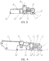
- Fig. 3
- shows a detail of Fig. 1 or Fig. 2, respectively, relating to the mounting element of the hinge arm;
- Fig. 4
- shows a detail of Fig. 1 or Fig. 2, respectively, relating to the interrelation of the mounting element of Fig. 3 and the hinge arm;
- Fig. 5
- shows a detail of Fig. 1 or Fig. 2, respectively, relating to a base plate and to the connection thereof with the furniture side wall, separately shown a sectional view along the line A-A; and
- Fig. 6
- shows a detail of Fig. 1 or Fig. 2, respectively, relating to the interrelation of the mounting element of the hinge arm of Fig. 3 and the assembly of the base plate and the furniture side wall of Fig. 5.
- From Fig. 1 the connection of the
furniture side wall 9 and thehinge arm 1 is evident. The connection is created indirectly by thebase plate 4, which is fixed by twoscrews 8 to theside wall 9 and with which is connectable or from which is disconnectable themounting element 2, which is permanently, but disconnectably, joined to thehinge arm 1. The assembly of thehinge arm 1 and themounting element 2 can at one end be connected to thebase plate 4 by a form-locking interconnection and at the other end connected by a force-locking interconnection which is based on spring elasticity. - The
hinge arm 1 and themounting element 2 are mutually connected by ascrew 5. The mating surfaces of thehinge arm 1 and themounting element 2 are uniformly ribbed or indented, the ribs or teeth of one element mating the spaces of teeth of the other one. Conveniently, a tapped hole for thescrew 5 is provided in themounting element 2, whereas thehinge arm 1 is provided with anelongated recess 1I which enables attaining optimum mutual position of thehinge arm 1 to themounting element 2 with respect to the state of incorporation. In order to avoid complete unscrewing of thescrew 5 at every mounting operation therecess 1I is at one end suitably widened with respect to the outline of the head of thescrew 5. - To enable adjustment of the slope of the
hinge arm 1 to themounting element 2 thehinge arm 1 is in the area between thescrew 5 and its end provided for the pivoted connection to the wing part of the hinge provided with a tapped hole into which ascrew 6 is inserted which regarding its head is not standardized; it namely ends in the direction towards themounting element 2 by a club-shaped termination of cylindrical cross-section, the latter being separated from the threaded part of thescrew 6 by a circular neck part the length of which corresponds to the thickness of the respective wall of themounting element 2, whereby the diameter of the neck part corresponds to the nominal width of an elongated open recess in said wall of themounting element 2 so that between thescrew 6 and the mounting element 2 a form-locking connection is formed. - Advantageously, the
mounting element 2 is formed as a capsized trough having open end sections and an inside attachment projecting from the roof wall and provided with said tapped hole for thescrew 5. The longitudinal side walls of themounting element 2 are close to their bottom edges at the free end below the elongated open recess serving thescrew 6 interconnected by means of acrossbeam 2I whose function is disclosed hereinafter. The side longitudinal walls of themounting element 2 are mutually connected also at the end opposite to thecrossbeam 2I; the connection is realized by ananalogous crossbeam 2II whose function is disclosed hereinafter. - Into the
space 2V between the longitudinal walls of themounting element 2, an attachment for the tapped hole for thescrew 5 and saidcrossbeam 2II there is inserted aslider 3 which combines several functions. Between theslider 3 and said tapped-hole attachment is inserted a pressure (spreading)spring 7 for which in theslider 3 is foreseen a scuttledbearing 3III, an analogous bearing being foreseen in the wall of the tapped-hole attachment. - In the axis of the
spring 7 theslider 3 is from the outer side formed as apusher stud 3II. Separated by aslot 3IV from thepusher stud 3II is alatch 3I. Theslot 3IV is regarding shape and location adapted to thecrosspiece 2II, the length of thelatch 3I being adapted to the available stroke of theslider 3 and enlarged for the necessary locking length. Advantageously, thepusher stud 3II is with respect to the object embodied so that in the pushed-in position the actuation surface thereof is essentially coplanar to the end surface of the assembledhinge arm 1 and themounting element 2. The freedom of movement of theslider 3 is thus precisely defined. - It is understood that the
base plate 4 is adapted to be fixed to thefurniture side wall 9 and to receive themounting element 2 as well as thehinge arm 1 joined to the latter. According to the inventive idea thebase plate 4 is systematically divided into two functional sections: A first section arranged in the area beneath thescrew 6, and a second section arranged in the area beneath thespring 7. The first section is characterized by the location of an elevatedportion 4II over the system plane of thebase plate 4, beneath which elevated portion 4II a recess is provided in the plate, the second section being characterized by an arrangement of acrossbeam 4I also arranged over the system plane of theplate 4 and beneath which arecess 4V is foreseen as well. A hole for inserting afastening screw 8 is foreseen both in the area preceding thefree end 4III of the elevatedportion 4II and in the middle between the above-mentioned sections. Atransition piece 4IV interconnecting the 4II elevated portion at its opposite side of thefree end 4III and the second section of thebase plate 4 is embodied with a solid wall providing an abutment for arespective tongue 2III of themounting element 2. - The side walls of the trough-
shaped mounting element 2 are in the area of thescrew 5 each provided with aband appendage 2IV which at mating themounting element 2 with thebase plate 4 cooperate with arecess 4V of the latter. With the aim that the lengths of the band appendages 2IV and therecess 4V be registered the latter is longitudinally enlarged laterally on both sides of thescrew 8 with respect to the longitudinal plane of symmetry of the assembly (not evident from the drawing). - When positioning the assembly of the
hinge arm 1 and the mountingelement 2 with the corresponding equipment onto thebase plate 4, thecrossbeam 2I is approached to thefree end 4III of theelevated portion 4II and placed below it. In this position the latch 3' strikes thecrossbeam 4I. In the preferred embodiment of the invention the cooperating front edges of thelatch 3I and thecrossbeam 4I are conveniently rounded off or bevelled, such characteristic properties of thespring 7 being chosen that thelatch 3I slides below thecrossbeam 4I without necessity of thepusher stud 3II to be pushed. It is understood that thereby the twoband appendages 2IV and thecorresponding recess 4V provide flawless guiding of one element against the other also in the direction transversely to the longitudinal axis. - Dismounting the assembly of the
hinge arm 1 and the mountingelement 2 as well as the corresponding equipment from thebase plate 4, which practically means taking off the door wing from a furniture side wall, represents a reverse operation: One pushes thepusher stud 3II, i.e. one causes a stroke of thelatch 3I from below thecrossbeam 4I, simultaneously two fingers of the same hand grip the removable assembly, lift it from thebase plate 4 and move it in the direction to the operator, thereby disengaging thecrossbeam 2I from theelevated portion 4II. - It is obvious that all needed movements can be realized with one hand, the other hand being free to hold the door wing. No additional operator is necessary.
Claims (3)
- Furniture hinge comprising- a base plate (4),- a hinge arm (1) with a mounting assembly housed therein,- said mounting assembly consisting of a mounting element (2) and a single spring-loaded slider (3) housed therein, said spring-loaded slider (3) being slidable in the longitudinal direction of said hinge arm (1) for engaging said base plate (4),
characterized in that
said mounting assembly is locked to said base plate (4) bya) a first mounting element crossbeam (2I) provided at the end of said mounting element (2) facing the pivot of said hinge arm (1), which engages from below a free end section (4III) of an elevated portion (4II) of said base plate (4),b) a tongue (2III) abutting against a transition piece (4IV) of said base plate (4), the transition piece (4IV) interconnecting said elevated portion (4II) of said base plate (4) and a lower section thereof facing away from the pivot of said hinge arm (1), andc) a latch (3I) provided at said slider (3), which engages from below a crossbeam (4I) of said base plate (4) arranged at the end of the base plate (4) remote from the pivot of the hinge arm (1). - Furniture hinge according to claim 1, characterized in that the slider (3) comprises a pusher stud (3II) arranged in the axis of the spring (7), the pusher stud (3II) being separated from the latch (3I) by a slot (3IV).
- Furniture hinge according to claim 2, characterized in that a second mounting element crossbeam (2II) is provided at the end of the mounting element (2) which is opposite to the end where the first mounting element crossbeam (2I) is provided, the dimension and position of the slot (3IV) corresponding to the second mounting element crossbeam (2II).
Priority Applications (9)
| Application Number | Priority Date | Filing Date | Title |
|---|---|---|---|
| ES90125572T ES2086360T3 (en) | 1990-12-27 | 1990-12-27 | QUICK MOUNT FURNITURE HINGE. |
| AT90125572T ATE135079T1 (en) | 1990-12-27 | 1990-12-27 | QUICK CONNECTION FURNITURE HINGE |
| DE69025767T DE69025767T2 (en) | 1990-12-27 | 1990-12-27 | Quick connect furniture hinge |
| EP90125572A EP0491990B1 (en) | 1990-12-27 | 1990-12-27 | Quick-assembling furniture hinge |
| HU912229A HU207565B (en) | 1990-12-27 | 1991-07-02 | Furniture joint |
| PL29112791A PL291127A1 (en) | 1990-12-27 | 1991-07-18 | Quick attachable furniture hinge |
| MX9100847A MX173922B (en) | 1990-12-27 | 1991-08-28 | HINGE FOR FAST MOUNTING FURNITURE |
| JP3342936A JPH0693767A (en) | 1990-12-27 | 1991-12-25 | Hinge for quick assembly type furniture |
| GR960400695T GR3019569T3 (en) | 1990-12-27 | 1996-04-08 | Quick-assembling furniture hinge |
Applications Claiming Priority (1)
| Application Number | Priority Date | Filing Date | Title |
|---|---|---|---|
| EP90125572A EP0491990B1 (en) | 1990-12-27 | 1990-12-27 | Quick-assembling furniture hinge |
Publications (2)
| Publication Number | Publication Date |
|---|---|
| EP0491990A1 EP0491990A1 (en) | 1992-07-01 |
| EP0491990B1 true EP0491990B1 (en) | 1996-03-06 |
Family
ID=8204898
Family Applications (1)
| Application Number | Title | Priority Date | Filing Date |
|---|---|---|---|
| EP90125572A Expired - Lifetime EP0491990B1 (en) | 1990-12-27 | 1990-12-27 | Quick-assembling furniture hinge |
Country Status (9)
| Country | Link |
|---|---|
| EP (1) | EP0491990B1 (en) |
| JP (1) | JPH0693767A (en) |
| AT (1) | ATE135079T1 (en) |
| DE (1) | DE69025767T2 (en) |
| ES (1) | ES2086360T3 (en) |
| GR (1) | GR3019569T3 (en) |
| HU (1) | HU207565B (en) |
| MX (1) | MX173922B (en) |
| PL (1) | PL291127A1 (en) |
Cited By (1)
| Publication number | Priority date | Publication date | Assignee | Title |
|---|---|---|---|---|
| CN111255322A (en) * | 2020-03-07 | 2020-06-09 | 夏勇辉 | Detachable hinge |
Families Citing this family (2)
| Publication number | Priority date | Publication date | Assignee | Title |
|---|---|---|---|---|
| DE29813447U1 (en) | 1998-07-28 | 1998-11-05 | Salice Arturo Spa | Fastening plate for fastening a fitting part, e.g. of a hinge arm on a supporting wall |
| DE29822770U1 (en) | 1998-12-21 | 1999-02-18 | Arturo Salice S.P.A., Novedrate, Como | hinge |
Family Cites Families (4)
| Publication number | Priority date | Publication date | Assignee | Title |
|---|---|---|---|---|
| DE3525279A1 (en) * | 1985-07-16 | 1987-01-29 | Lautenschlaeger Kg Karl | FURNITURE HINGE |
| DE3544487A1 (en) * | 1985-07-16 | 1987-06-19 | Lautenschlaeger Kg Karl | Furniture hinge |
| DE3627170C1 (en) * | 1986-08-11 | 1988-03-24 | Salice Arturo Spa | Hinge arm for a furniture hinge or the like, can be connected directly or indirectly to the base plate |
| ES1009089Y (en) * | 1989-02-17 | 1989-12-16 | Blanco Eguiluz M. Begona | QUICK COUPLING DEVICE FOR FURNITURE HINGES. |
-
1990
- 1990-12-27 DE DE69025767T patent/DE69025767T2/en not_active Expired - Fee Related
- 1990-12-27 AT AT90125572T patent/ATE135079T1/en not_active IP Right Cessation
- 1990-12-27 ES ES90125572T patent/ES2086360T3/en not_active Expired - Lifetime
- 1990-12-27 EP EP90125572A patent/EP0491990B1/en not_active Expired - Lifetime
-
1991
- 1991-07-02 HU HU912229A patent/HU207565B/en not_active IP Right Cessation
- 1991-07-18 PL PL29112791A patent/PL291127A1/en unknown
- 1991-08-28 MX MX9100847A patent/MX173922B/en not_active IP Right Cessation
- 1991-12-25 JP JP3342936A patent/JPH0693767A/en active Pending
-
1996
- 1996-04-08 GR GR960400695T patent/GR3019569T3/en unknown
Cited By (1)
| Publication number | Priority date | Publication date | Assignee | Title |
|---|---|---|---|---|
| CN111255322A (en) * | 2020-03-07 | 2020-06-09 | 夏勇辉 | Detachable hinge |
Also Published As
| Publication number | Publication date |
|---|---|
| GR3019569T3 (en) | 1996-07-31 |
| DE69025767T2 (en) | 1996-09-05 |
| JPH0693767A (en) | 1994-04-05 |
| HU912229D0 (en) | 1991-12-30 |
| ES2086360T3 (en) | 1996-07-01 |
| EP0491990A1 (en) | 1992-07-01 |
| DE69025767D1 (en) | 1996-04-11 |
| HUT60826A (en) | 1992-10-28 |
| MX173922B (en) | 1994-04-08 |
| HU207565B (en) | 1993-04-28 |
| PL291127A1 (en) | 1992-06-26 |
| MX9100847A (en) | 1992-11-01 |
| ATE135079T1 (en) | 1996-03-15 |
Similar Documents
| Publication | Publication Date | Title |
|---|---|---|
| US4998828A (en) | Over and under telescoping slide assembly | |
| US6871920B2 (en) | Quick-mount support system for telescoping slide | |
| US6851985B2 (en) | Connection device for an electronic box | |
| US8322034B2 (en) | Apparatus and method for the insertion and withdrawal of plug-in modules | |
| GB2169950A (en) | Buckle for watch bands | |
| JPH0349702A (en) | Assembly of belt clasp-tongue- shaped body | |
| US6112373A (en) | Clasp assembly | |
| KR930018800A (en) | Drawout breaker | |
| JPH06124U (en) | Inner clasp of watch band | |
| US4609119A (en) | Retaining device for mounting electrical units | |
| US5224242A (en) | Quick-assembling furniture hinge | |
| US5299095A (en) | Apparatus for detachably fastening an equipment housing to a profile rail | |
| EP0491990B1 (en) | Quick-assembling furniture hinge | |
| KR100196002B1 (en) | Automatic lock slider for slide fastener | |
| US5316164A (en) | Housing suitable for wall or bottom fastening | |
| JP3446862B2 (en) | Slider for slide fastener with stop device | |
| US6398575B1 (en) | Locking device for electrical connector | |
| PL367049A1 (en) | Electrical connector | |
| JPH05502975A (en) | Rapid installation mechanism for connected electrical devices | |
| AU687208B2 (en) | A connector for supporting an object along an elongated track | |
| JPH0754506Y2 (en) | Electric lock | |
| JPH04115073A (en) | Hinge | |
| JP2573372Y2 (en) | Mounting structure of socket cover in fluorescent lamp unit | |
| AU725346B2 (en) | Device for attaching an electrical switch unit to a bus bar and a mounting rail | |
| JPH04228785A (en) | Hinge |
Legal Events
| Date | Code | Title | Description |
|---|---|---|---|
| PUAI | Public reference made under article 153(3) epc to a published international application that has entered the european phase |
Free format text: ORIGINAL CODE: 0009012 |
|
| AK | Designated contracting states |
Kind code of ref document: A1 Designated state(s): AT BE CH DE DK ES FR GB GR IT LI LU NL SE |
|
| 17P | Request for examination filed |
Effective date: 19921201 |
|
| 17Q | First examination report despatched |
Effective date: 19940525 |
|
| GRAA | (expected) grant |
Free format text: ORIGINAL CODE: 0009210 |
|
| AK | Designated contracting states |
Kind code of ref document: B1 Designated state(s): AT BE CH DE DK ES FR GB GR IT LI LU NL SE |
|
| PG25 | Lapsed in a contracting state [announced via postgrant information from national office to epo] |
Ref country code: NL Free format text: LAPSE BECAUSE OF FAILURE TO SUBMIT A TRANSLATION OF THE DESCRIPTION OR TO PAY THE FEE WITHIN THE PRESCRIBED TIME-LIMIT Effective date: 19960306 Ref country code: LI Effective date: 19960306 Ref country code: GR Free format text: LAPSE BECAUSE OF FAILURE TO SUBMIT A TRANSLATION OF THE DESCRIPTION OR TO PAY THE FEE WITHIN THE PRESCRIBED TIME-LIMIT Effective date: 19960306 Ref country code: DK Effective date: 19960306 Ref country code: CH Effective date: 19960306 Ref country code: BE Effective date: 19960306 Ref country code: AT Effective date: 19960306 |
|
| REF | Corresponds to: |
Ref document number: 135079 Country of ref document: AT Date of ref document: 19960315 Kind code of ref document: T |
|
| REF | Corresponds to: |
Ref document number: 69025767 Country of ref document: DE Date of ref document: 19960411 |
|
| ITF | It: translation for a ep patent filed | ||
| ET | Fr: translation filed | ||
| PG25 | Lapsed in a contracting state [announced via postgrant information from national office to epo] |
Ref country code: SE Effective date: 19960606 |
|
| REG | Reference to a national code |
Ref country code: GR Ref legal event code: FG4A Free format text: 3019569 |
|
| REG | Reference to a national code |
Ref country code: ES Ref legal event code: FG2A Ref document number: 2086360 Country of ref document: ES Kind code of ref document: T3 |
|
| NLV1 | Nl: lapsed or annulled due to failure to fulfill the requirements of art. 29p and 29m of the patents act | ||
| REG | Reference to a national code |
Ref country code: CH Ref legal event code: PL |
|
| PG25 | Lapsed in a contracting state [announced via postgrant information from national office to epo] |
Ref country code: GB Effective date: 19961227 |
|
| PG25 | Lapsed in a contracting state [announced via postgrant information from national office to epo] |
Ref country code: ES Free format text: LAPSE BECAUSE OF THE APPLICANT RENOUNCES Effective date: 19961228 |
|
| PG25 | Lapsed in a contracting state [announced via postgrant information from national office to epo] |
Ref country code: LU Free format text: LAPSE BECAUSE OF NON-PAYMENT OF DUE FEES Effective date: 19961231 |
|
| PLBE | No opposition filed within time limit |
Free format text: ORIGINAL CODE: 0009261 |
|
| STAA | Information on the status of an ep patent application or granted ep patent |
Free format text: STATUS: NO OPPOSITION FILED WITHIN TIME LIMIT |
|
| 26N | No opposition filed | ||
| REG | Reference to a national code |
Ref country code: GR Ref legal event code: MM2A Free format text: 3019569 |
|
| GBPC | Gb: european patent ceased through non-payment of renewal fee |
Effective date: 19961227 |
|
| PG25 | Lapsed in a contracting state [announced via postgrant information from national office to epo] |
Ref country code: FR Effective date: 19970829 |
|
| REG | Reference to a national code |
Ref country code: FR Ref legal event code: ST |
|
| REG | Reference to a national code |
Ref country code: ES Ref legal event code: FD2A Effective date: 20010402 |
|
| PGFP | Annual fee paid to national office [announced via postgrant information from national office to epo] |
Ref country code: DE Payment date: 20050224 Year of fee payment: 15 |
|
| PG25 | Lapsed in a contracting state [announced via postgrant information from national office to epo] |
Ref country code: IT Free format text: LAPSE BECAUSE OF NON-PAYMENT OF DUE FEES;WARNING: LAPSES OF ITALIAN PATENTS WITH EFFECTIVE DATE BEFORE 2007 MAY HAVE OCCURRED AT ANY TIME BEFORE 2007. THE CORRECT EFFECTIVE DATE MAY BE DIFFERENT FROM THE ONE RECORDED. Effective date: 20051227 |
|
| PG25 | Lapsed in a contracting state [announced via postgrant information from national office to epo] |
Ref country code: DE Free format text: LAPSE BECAUSE OF NON-PAYMENT OF DUE FEES Effective date: 20060701 |