EP0491507A2 - Method and apparatus for stacking pasted battery plates - Google Patents
Method and apparatus for stacking pasted battery plates Download PDFInfo
- Publication number
- EP0491507A2 EP0491507A2 EP91311346A EP91311346A EP0491507A2 EP 0491507 A2 EP0491507 A2 EP 0491507A2 EP 91311346 A EP91311346 A EP 91311346A EP 91311346 A EP91311346 A EP 91311346A EP 0491507 A2 EP0491507 A2 EP 0491507A2
- Authority
- EP
- European Patent Office
- Prior art keywords
- conveyor
- plates
- stack
- conveyor means
- moving
- Prior art date
- Legal status (The legal status is an assumption and is not a legal conclusion. Google has not performed a legal analysis and makes no representation as to the accuracy of the status listed.)
- Granted
Links
Images


Classifications
-
- H—ELECTRICITY
- H01—ELECTRIC ELEMENTS
- H01M—PROCESSES OR MEANS, e.g. BATTERIES, FOR THE DIRECT CONVERSION OF CHEMICAL ENERGY INTO ELECTRICAL ENERGY
- H01M10/00—Secondary cells; Manufacture thereof
- H01M10/04—Construction or manufacture in general
-
- B—PERFORMING OPERATIONS; TRANSPORTING
- B65—CONVEYING; PACKING; STORING; HANDLING THIN OR FILAMENTARY MATERIAL
- B65H—HANDLING THIN OR FILAMENTARY MATERIAL, e.g. SHEETS, WEBS, CABLES
- B65H29/00—Delivering or advancing articles from machines; Advancing articles to or into piles
- B65H29/66—Advancing articles in overlapping streams
-
- B—PERFORMING OPERATIONS; TRANSPORTING
- B65—CONVEYING; PACKING; STORING; HANDLING THIN OR FILAMENTARY MATERIAL
- B65H—HANDLING THIN OR FILAMENTARY MATERIAL, e.g. SHEETS, WEBS, CABLES
- B65H33/00—Forming counted batches in delivery pile or stream of articles
- B65H33/12—Forming counted batches in delivery pile or stream of articles by creating gaps in the stream
-
- H—ELECTRICITY
- H01—ELECTRIC ELEMENTS
- H01M—PROCESSES OR MEANS, e.g. BATTERIES, FOR THE DIRECT CONVERSION OF CHEMICAL ENERGY INTO ELECTRICAL ENERGY
- H01M10/00—Secondary cells; Manufacture thereof
- H01M10/04—Construction or manufacture in general
- H01M10/0404—Machines for assembling batteries
-
- Y—GENERAL TAGGING OF NEW TECHNOLOGICAL DEVELOPMENTS; GENERAL TAGGING OF CROSS-SECTIONAL TECHNOLOGIES SPANNING OVER SEVERAL SECTIONS OF THE IPC; TECHNICAL SUBJECTS COVERED BY FORMER USPC CROSS-REFERENCE ART COLLECTIONS [XRACs] AND DIGESTS
- Y02—TECHNOLOGIES OR APPLICATIONS FOR MITIGATION OR ADAPTATION AGAINST CLIMATE CHANGE
- Y02P—CLIMATE CHANGE MITIGATION TECHNOLOGIES IN THE PRODUCTION OR PROCESSING OF GOODS
- Y02P70/00—Climate change mitigation technologies in the production process for final industrial or consumer products
- Y02P70/50—Manufacturing or production processes characterised by the final manufactured product
Definitions
- This invention relates to a machine for forming vertical stacks of plates from a stream of plates transported horizontally on a conveyor in a shingled fashion.
- the plates used in storage batteries are formed by placing a lead oxide paste on a cast grid.
- the plates are then flash dried to remove moisture from the paste and cause it to set up. This process is accomplished in a pasted plate machine which is standard in the industry. All of the moisture is not removed from the plates during flash drying, however, and thus the plates that are discharged from the plate machine are not completely rigid and are somewhat tacky.
- the plates exit the machine on an output conveyor at a high rate of speed which makes them difficult to handle and form into the horizontal stacks which are used in the remainder in the battery construction process.
- the plates have been deposited onto a slower speed conveyor and then removed from the slower conveyor and formed into stacks by hand. Due to its lower speed, the plates are deposited on the slower conveyor in an overlapping shingled fashion. Thus, they can be removed simply by stopping movement of the first plate with one hand which causes the plates to bunch together so that a group of the plates can be lifted off of the conveyor and formed into a stack. Since the stacks are quite heavy and the machines create a hot dusty environment, this is a difficult job and it is desirable to automate the stacking process.
- Prior art machines have been provided to stack plates from a pasted plate machine. However, the difficulty in causing a pause between plates in a shingled stream of plates, as is necessary for removal of the stacks, has caused these machines to handle plates moving at the high output speed of the plate machine, or even increase their speed to form a separation between plates.
- Prior art stackers of this type are manufactured by Wirtz Manufacturing Co., Inc. of Port Huron, Michigan and Uranio SpA, Sovema Division via Torricelli of Verona, Italy. These prior art devices have been able to form stacks by diverting plates or temporarily supporting plates to create a pause between stacks.
- the subject invention overcomes the short-comings of the prior art by forming vertical stacks of plates from a shingled stream by merely allowing the plates to drop off at the discharge end of the slower speed conveyor they are being carried on onto a second conveyor that is not moving until a stack is formed on the second conveyor. Each completed stack is then removed by moving the second conveyor after the last plate is deposited on the stack.
- the stream of plates is prevented from moving with the first conveyor when the second conveyor is being moved in order to create the necessary pause between stacks. This preferably is accomplished by squeezing the plates between the jaws of a clamp mechanism. Because clamping is equally effective over the entire length of a plate, slight variations in timing of the plates does not create a problem, particularly when the plates are traveling on a slower speed conyeyor when the clamping occurs.
- a raisable gate located across the second conveyor engages the plates as they fall from the first conveyor and causes the stacks to be straight.
- a controller activates the clamp when the proper number of plates has passed the clamp. After a sufficient time for the plates downstream of the clamp to be discharged and complete the stack, the controller raises the gate and starts the second conveyor moving. After the stack has been moved out of the way the controller stops the second conveyor, lowers the gate and releases the clamp and another stack is formed.
- the controller can be annunciated by a counter that counts the plates on the second conveyor or by a sensor that measures the height of the stack.
- two side-by-side second conveyors are provided. If it is desired to align the plates transversely on the conveyors before they are displaced onto a stack, the conveyors can diverge from one another in order to allow an alignment machine to be placed on each side of both conveyors.
- FIG. 1 is a foreshortened plan view, partially broken away to show hidden detail, of a plate stacking machine embodying the subject invention.
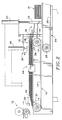
- FIG. 2 is a sectional view taken along the line 2-2 in FIG. 1.
- FIGS. 3 and 4 are fragmentary sectional views, similar to FIG. 2, showing the sequence of operation of the machine.
- a stacker embodying the features of the subject invention comprises a pair of side-by-side first conveyors 10 which are located slightly below the end of the output conveyor 12 of a pasted plate manufacturing machine.
- the pasted plate machine which is standard in the industry, produces battery plates in side-by-side pairs at a high rate of speed.
- Each first conveyor is illustrated as utilizing a pair of spaced-apart continuous chains 13 that are carried on rotatable sprockets 14. The sprockets at one end of the first conveyors are driven by a drive motor 16.
- the first conveyors are aligned to receive plates from the plate machine output conveyor and move them in generally the same direction that they were traveling, however, the two first conveyors diverge relative to one another as they extend away from the plate machine. In addition, the first conveyors travel at a much slower speed than the output conveyor. Thus, the adjacent side-by-side plates 18 from the plate machine drop off of the end of the output conveyor onto the first conveyors in an overlapping manner to provide two streams of shingled plates which are separated from one another when they reach the discharge ends 19 of the first conveyors.
- a counter 20 is located at the inlet ends 21 of the first conveyors 10 to count each pair of plates that drops onto the first conveyors.
- a timer could be used in place of the counter or an electric eye could be used to determine when the stack reaches the desired height.
- the counter 20 or other device annunciates a controller 22 that controls the operation of the stacker.
- the first and second conveyors are illustrated as being generally axially aligned with one another but they do not have to be.
- the second conveyors are vertically separated from the first conveyors by a distance which is slightly more than the height of the largest stack that will be formed.
- the second conveyors include pairs of side-by-side endless chains 26 that are carried on sprockets 28.
- the second conveyor 24 is driven by the motor 16 through a chain 29.
- a clutch 30 associated with the second conveyor permits it to be stopped and started without stopping the motor 16.
- the motor 16 and clutch 30 are controlled by the controller 22 which receives input from the counter 20.
- the first conveyors 10 move whenever the stacker is in operation.
- plates that drop off of the discharge ends 19 of the first conveyors form vertical stacks 31 on the second conveyors.
- a gate 32 is removably placed across each second conveyor approximately one plate width from the discharge ends of the first conveyors. The plates lightly strike the gate as they fall downwardly and forwardly, thereby causing the stacks to be straight.
- the gates 32 are attached to actuators 34 which allow them to be moved between lowered positions adjacent to the second conveyors and raised positions above the height of the stacks. The actuators 34 are moved between their raised and lowered positions by the controller 22.
- a clamping mechanism 36 engages the plates and prevents them from moving with the conveyors.
- the clamping mechanism includes an elongate roller 38 that fits between the chains of each first conveyor and projects slightly above the plane of the chains. Thus, the plates are lifted off of the conveyors as they pass over the rollers 38.
- an actuator 40 Located above each roller 38 is an actuator 40 that has a pinch plate 42 attached to its piston. The pinch plates have approximately the same length as the rollers 38 that they mate with.
- the actuators 40 are controlled by the controller 22 and are movable between lowered positions, FIGS. 3 and 4, where the plates are clamped between the pinch plates and rollers, and raised positions above the plates. Since it does not matter where the clamp contacts the plate, timing is not as critical as it is when plates are diverted. The fact that the plates are traveling on a relatively low speed conveyor makes timing even less of an issue.
- the divergence of the first conveyors permits an alignment apparatus, shown schematically at 44, to be placed near the discharge ends of the first conveyors.
- plates 18 exiting the output conveyor of the plate machine are accumulated on the slower speed first conveyors 10 in a shingled stream. As the plates reach the discharge ends 19 of the first conveyors, they drop onto the second conveyors and form stacks 31.
- the controller 22 causes the actuators 40 to move the pinch plates 42 downwardly and clamp the plates between the pinch plates and the rollers 38, FIG. 3. Since the rollers raise the plates above the conveyors, the pinch plates do not clamp the plates against the chains and the conveyors can continue to operate unimpeded. This causes the following plates to bunch up slightly but only over a short distance.
- the controller causes the actuators 34 to raise the gates 32 and engages the clutch 30 to start operation of the second conveyors 24, FIG. 4.
- the controller causes the clutch 30 to be disengaged, the actuators 34 to lower the gates 32 and the actuators 40 to raise the pinch plates 42. Plates will then again be discharged from the first conveyors and start forming the next set of stacks.
Landscapes
- Engineering & Computer Science (AREA)
- General Chemical & Material Sciences (AREA)
- Manufacturing & Machinery (AREA)
- Chemical & Material Sciences (AREA)
- Chemical Kinetics & Catalysis (AREA)
- Electrochemistry (AREA)
- Mechanical Engineering (AREA)
- Secondary Cells (AREA)
- Forming Counted Batches (AREA)
- Battery Electrode And Active Subsutance (AREA)
- Primary Cells (AREA)
- Sealing Battery Cases Or Jackets (AREA)
- Pile Receivers (AREA)
- Stacking Of Articles And Auxiliary Devices (AREA)
Abstract
Description
- This invention relates to a machine for forming vertical stacks of plates from a stream of plates transported horizontally on a conveyor in a shingled fashion.
- The plates used in storage batteries are formed by placing a lead oxide paste on a cast grid. The plates are then flash dried to remove moisture from the paste and cause it to set up. This process is accomplished in a pasted plate machine which is standard in the industry. All of the moisture is not removed from the plates during flash drying, however, and thus the plates that are discharged from the plate machine are not completely rigid and are somewhat tacky. The plates exit the machine on an output conveyor at a high rate of speed which makes them difficult to handle and form into the horizontal stacks which are used in the remainder in the battery construction process.
- Traditionally, the plates have been deposited onto a slower speed conveyor and then removed from the slower conveyor and formed into stacks by hand. Due to its lower speed, the plates are deposited on the slower conveyor in an overlapping shingled fashion. Thus, they can be removed simply by stopping movement of the first plate with one hand which causes the plates to bunch together so that a group of the plates can be lifted off of the conveyor and formed into a stack. Since the stacks are quite heavy and the machines create a hot dusty environment, this is a difficult job and it is desirable to automate the stacking process.
- In other industries plates that are provided in a shingled fashion are stacked by interrupting the movement of the first plate, thereby causing the plates to stand up on end and form a horizontal stack which can be removed with a clamping mechanism. However, freshly made battery plates are not slippery enough or stiff enough to form stacks in this manner.
- Prior art machines have been provided to stack plates from a pasted plate machine. However, the difficulty in causing a pause between plates in a shingled stream of plates, as is necessary for removal of the stacks, has caused these machines to handle plates moving at the high output speed of the plate machine, or even increase their speed to form a separation between plates. Prior art stackers of this type are manufactured by Wirtz Manufacturing Co., Inc. of Port Huron, Michigan and Uranio SpA, Sovema Division via Torricelli of Verona, Italy. These prior art devices have been able to form stacks by diverting plates or temporarily supporting plates to create a pause between stacks. However, due to the high speed involved, slight variations in the timing of the arrival of plates at the diversion device cause the diversion to often be too early or too late. As a result errors occur which make the machines unreliable. In addition, the high speed sorting makes the machines extremely expensive. Accordingly, hand stacking remains the norm.
- The subject invention overcomes the short-comings of the prior art by forming vertical stacks of plates from a shingled stream by merely allowing the plates to drop off at the discharge end of the slower speed conveyor they are being carried on onto a second conveyor that is not moving until a stack is formed on the second conveyor. Each completed stack is then removed by moving the second conveyor after the last plate is deposited on the stack. The stream of plates is prevented from moving with the first conveyor when the second conveyor is being moved in order to create the necessary pause between stacks. This preferably is accomplished by squeezing the plates between the jaws of a clamp mechanism. Because clamping is equally effective over the entire length of a plate, slight variations in timing of the plates does not create a problem, particularly when the plates are traveling on a slower speed conyeyor when the clamping occurs.
- In a preferred embodiment, a raisable gate located across the second conveyor engages the plates as they fall from the first conveyor and causes the stacks to be straight. Also in the preferred embodiment, a controller activates the clamp when the proper number of plates has passed the clamp. After a sufficient time for the plates downstream of the clamp to be discharged and complete the stack, the controller raises the gate and starts the second conveyor moving. After the stack has been moved out of the way the controller stops the second conveyor, lowers the gate and releases the clamp and another stack is formed. The controller can be annunciated by a counter that counts the plates on the second conveyor or by a sensor that measures the height of the stack.
- Since plate making machines typically produce plates in side-by-side pairs, two side-by-side second conveyors are provided. If it is desired to align the plates transversely on the conveyors before they are displaced onto a stack, the conveyors can diverge from one another in order to allow an alignment machine to be placed on each side of both conveyors.
- Accordingly, it is a principal object of the subject invention to provide a method for forming a vertical stack of plates from a shingled stream of horizontally oriented plates.
- It is a further object of the present invention to also provide a disruption in the flow of the plates while a completed stack is being moved from the spot where it is formed.
- It is a still further object of the subject invention to provide an apparatus for practicing the foregoing method.
- It is a further object, at least in preferred embodiments of the subject invention, to provide such an apparatus which is not affected by variations in the timing of the plates.
- It is a yet further object, at least in preferred embodiments of the present invention, to provide such an apparatus that clamps the plates to disrupt their flow.
- It is a further object, at least in preferred embodiments of the subject invention, to provide such an apparatus that causes side-by-side pairs of plates from the plate making machine to be separated from one another before they are formed into stacks to facilitate lateral alignment of the plates.
- The foregoing and other objectives, features and advantages of the present invention will be more readily understood upon consideration of the following detailed description of the invention taken in conjunction with the accompanying drawings.
- FIG. 1 is a foreshortened plan view, partially broken away to show hidden detail, of a plate stacking machine embodying the subject invention.
- FIG. 2 is a sectional view taken along the line 2-2 in FIG. 1.
- FIGS. 3 and 4 are fragmentary sectional views, similar to FIG. 2, showing the sequence of operation of the machine.
- Referring to FIGS. 1 and 2 of the drawings, a stacker embodying the features of the subject invention comprises a pair of side-by-side
first conveyors 10 which are located slightly below the end of theoutput conveyor 12 of a pasted plate manufacturing machine. The pasted plate machine, which is standard in the industry, produces battery plates in side-by-side pairs at a high rate of speed. Each first conveyor is illustrated as utilizing a pair of spaced-apartcontinuous chains 13 that are carried onrotatable sprockets 14. The sprockets at one end of the first conveyors are driven by adrive motor 16. The first conveyors are aligned to receive plates from the plate machine output conveyor and move them in generally the same direction that they were traveling, however, the two first conveyors diverge relative to one another as they extend away from the plate machine. In addition, the first conveyors travel at a much slower speed than the output conveyor. Thus, the adjacent side-by-side plates 18 from the plate machine drop off of the end of the output conveyor onto the first conveyors in an overlapping manner to provide two streams of shingled plates which are separated from one another when they reach thedischarge ends 19 of the first conveyors. - In the embodiment illustrated, a
counter 20 is located at theinlet ends 21 of thefirst conveyors 10 to count each pair of plates that drops onto the first conveyors. Alternatively, a timer could be used in place of the counter or an electric eye could be used to determine when the stack reaches the desired height. Thecounter 20 or other device annunciates acontroller 22 that controls the operation of the stacker. - A pair of
second conveyors 24, which are similar to thefirst conveyors 10, are located below the discharge ends of the first conveyors. The first and second conveyors are illustrated as being generally axially aligned with one another but they do not have to be. The second conveyors are vertically separated from the first conveyors by a distance which is slightly more than the height of the largest stack that will be formed. The second conveyors include pairs of side-by-sideendless chains 26 that are carried onsprockets 28. Thesecond conveyor 24 is driven by themotor 16 through a chain 29. Aclutch 30 associated with the second conveyor permits it to be stopped and started without stopping themotor 16. Themotor 16 andclutch 30 are controlled by thecontroller 22 which receives input from thecounter 20. - The
first conveyors 10 move whenever the stacker is in operation. Thesecond conveyors 24, on the other hand, generally do not move. Thus, plates that drop off of thedischarge ends 19 of the first conveyors formvertical stacks 31 on the second conveyors. Because the plates have a forward velocity as they drop off the discharge ends of the first conveyors, agate 32 is removably placed across each second conveyor approximately one plate width from the discharge ends of the first conveyors. The plates lightly strike the gate as they fall downwardly and forwardly, thereby causing the stacks to be straight. Thegates 32 are attached to actuators 34 which allow them to be moved between lowered positions adjacent to the second conveyors and raised positions above the height of the stacks. Theactuators 34 are moved between their raised and lowered positions by thecontroller 22. - In order to stop the plates from exiting the discharge ends of the first conveyors when the second conveyors are moving, a
clamping mechanism 36 engages the plates and prevents them from moving with the conveyors. In the embodiment illustrated, the clamping mechanism includes anelongate roller 38 that fits between the chains of each first conveyor and projects slightly above the plane of the chains. Thus, the plates are lifted off of the conveyors as they pass over therollers 38. Located above eachroller 38 is an actuator 40 that has apinch plate 42 attached to its piston. The pinch plates have approximately the same length as therollers 38 that they mate with. Theactuators 40 are controlled by thecontroller 22 and are movable between lowered positions, FIGS. 3 and 4, where the plates are clamped between the pinch plates and rollers, and raised positions above the plates. Since it does not matter where the clamp contacts the plate, timing is not as critical as it is when plates are diverted. The fact that the plates are traveling on a relatively low speed conveyor makes timing even less of an issue. - While the plates from a plate machine are generally aligned, the divergence of the first conveyors permits an alignment apparatus, shown schematically at 44, to be placed near the discharge ends of the first conveyors.
- In operation,
plates 18 exiting the output conveyor of the plate machine are accumulated on the slower speedfirst conveyors 10 in a shingled stream. As the plates reach the discharge ends 19 of the first conveyors, they drop onto the second conveyors and form stacks 31. When the number of plates required to form a complete stack has been counted by thecounter 20, thecontroller 22 causes theactuators 40 to move thepinch plates 42 downwardly and clamp the plates between the pinch plates and therollers 38, FIG. 3. Since the rollers raise the plates above the conveyors, the pinch plates do not clamp the plates against the chains and the conveyors can continue to operate unimpeded. This causes the following plates to bunch up slightly but only over a short distance. - Once sufficient time has passed to permit the plates downstream of the
clamps 36 to drop onto the stacks, the controller causes theactuators 34 to raise thegates 32 and engages the clutch 30 to start operation of thesecond conveyors 24, FIG. 4. Once a sufficient time has passed so that the just-formed stacks are entirely downstream of the gates, the controller causes the clutch 30 to be disengaged, theactuators 34 to lower thegates 32 and theactuators 40 to raise thepinch plates 42. Plates will then again be discharged from the first conveyors and start forming the next set of stacks. - The terms and expressions which have been employed in the foregoing specification are used therein as terms of description and not of limitation, and there is no intention, in the use of such terms and expressions, of excluding equivalents of the features shown and described or portions thereof, it being recognized that the scope of the invention is defined and limited only by the claims which follow.
Claims (10)
- A method of forming vertical stacks from a stream of horizontally oriented plates that overlap one another in a shingled fashion, comprising:(a) feeding said stream of plates on a moving first conveyor such that said stream of plates moves along with said first conveyor;(b) placing a second conveyor below the end of said first conveyor with the vertical distance between said first and second conveyors being at least as great as the desired stack height;(c) allowing plates to drop off of the end of said first conveyor onto said second conveyor and form a stack while said second conveyor is not moving;(d) once a stack is completely formed, moving said second conveyor until the just-formed stack is no longer below said first conveyor, and then ceasing movement of said second conveyor; and(e) repeating steps (c) and (d) to form subsequent stacks.
- The method of claim 1, including the step of preventing the plates in said stream of plates which are located adjacent to the end of said first conveyor from moving with said first conveyor while said second conveyor is being moved.
- An apparatus for forming vertical stacks from a stream of horizontally oriented semi-rigid plates that overlap one another in a shingle fashion, comprising:(a) first conveyor means for feeding and continued movement of said stream of plates, said first conveyor means having a discharge end that the plates are discharged from;(b) second conveyor means located below said first conveyor means in a manner such that plates discharged from said discharge end land on said second conveyor means; and(c) means for incrementally moving said second conveyor means each time a stack is completed.
- The apparatus of claim 3 including interruption means for interrupting the discharge of plates from said first conveyor means when said second conveyor is moving, independent of the timing of the plates on the first conveyor means.
- The apparatus of claim 4 wherein said interruption means comprises a clamping mechanism having upper and lower opposed jaws which engage plates in said stream.
- The apparatus of claim 5 wherein said lower jaw is offset from said first conveyor means to raise plates passing over said lower jaw slightly above said first conveyor means.
- The apparatus of claim 3, including stop means associated with said second conveyor means and means for moving said stop means between a lowered position where plates discharge from said first conveyor means contact said stop means and a raised position where a stack of plates on second conveyor means can pass below said stop means.
- The apparatus of claim 4 including means for determining the number of plates being placed on the stack, and simultaneously activating said interruption means and moving said second conveyor means for a specified period of time when the stack contains a predetermined number of plates.
- The apparatus of claim 3 wherein there are two first conveyor means for receiving two adjacent streams of plates, and said first conveyor means diverges from one another progressing toward the discharge ends so that the plates in the adjacent streams are further separated from one another at the discharge ends than when they were received on said first conveyor means.
- The apparatus of claim 9, including alignment means associated with each of said first conveyor means to align the plates being carried on said first conveyor means.
Applications Claiming Priority (2)
| Application Number | Priority Date | Filing Date | Title |
|---|---|---|---|
| US07/628,469 US5129643A (en) | 1990-12-17 | 1990-12-17 | Apparatus for stacking pasted battery plates |
| US628469 | 1990-12-17 |
Publications (3)
| Publication Number | Publication Date |
|---|---|
| EP0491507A2 true EP0491507A2 (en) | 1992-06-24 |
| EP0491507A3 EP0491507A3 (en) | 1993-03-10 |
| EP0491507B1 EP0491507B1 (en) | 1995-04-26 |
Family
ID=24519008
Family Applications (1)
| Application Number | Title | Priority Date | Filing Date |
|---|---|---|---|
| EP91311346A Expired - Lifetime EP0491507B1 (en) | 1990-12-17 | 1991-12-05 | Method and apparatus for stacking pasted battery plates |
Country Status (6)
| Country | Link |
|---|---|
| US (1) | US5129643A (en) |
| EP (1) | EP0491507B1 (en) |
| JP (1) | JPH04277128A (en) |
| KR (1) | KR920013808A (en) |
| AT (1) | ATE121867T1 (en) |
| DE (1) | DE69109254T2 (en) |
Cited By (2)
| Publication number | Priority date | Publication date | Assignee | Title |
|---|---|---|---|---|
| NL1007942C2 (en) * | 1997-12-31 | 1999-07-01 | Hadewe Bv | In-line processing of flat objects. |
| CN103949748A (en) * | 2014-05-08 | 2014-07-30 | 长兴精盛液压机械有限公司 | Automatic enveloping, jar mounting and welding device and method thereof |
Families Citing this family (24)
| Publication number | Priority date | Publication date | Assignee | Title |
|---|---|---|---|---|
| US5383760A (en) * | 1993-11-01 | 1995-01-24 | Ohmstede-Cawley, Ltd. | Apparatus and method for container pattern-forming and palletizing |
| US5669754A (en) * | 1996-04-22 | 1997-09-23 | Advanced Dynamics Corporation Ltd. | Method and apparatus for collecting plates |
| CH693989A5 (en) * | 2000-05-12 | 2004-05-28 | Bobst Sa | Braking device of a work machine of sheet members. |
| CA2458384C (en) * | 2001-10-05 | 2010-06-22 | Ferag Ag | Method of processing sheet-like products, and apparatus for implementing the method |
| GB0509646D0 (en) * | 2005-05-12 | 2005-06-15 | Tbs Eng Ltd | Apparatus for forming groups of battery plates |
| US8533973B2 (en) * | 2008-12-02 | 2013-09-17 | Mac Engineering And Equipment Company, Inc. | Contact flash dryer and method of contact flash drying |
| CA2723571C (en) * | 2009-12-23 | 2017-12-19 | Dixie Consumer Products Llc | Pressware stop ramp and method for using the same |
| WO2011130405A1 (en) * | 2010-04-13 | 2011-10-20 | J&L Group International Llc | Sheet deceleration apparatus and method |
| EP2739553B1 (en) | 2011-08-04 | 2018-03-28 | Alliance Machine Systems International, LLC | Apparatus and method for stacking corrugated sheet material |
| US9048462B2 (en) * | 2012-03-29 | 2015-06-02 | GM Global Technology Operations LLC | Method of handling large format battery cells for high speed assembly |
| US8746436B2 (en) * | 2012-10-04 | 2014-06-10 | Dyco, Inc. | Apparatus and method for separating articles susceptible to cohesive grouping |
| JP6103945B2 (en) * | 2013-01-10 | 2017-03-29 | ユニ・チャーム株式会社 | Stacking apparatus and method for manufacturing web member |
| CN105015829B (en) * | 2014-04-30 | 2018-08-03 | 光荣株式会社 | Bale generates system |
| CN104326292A (en) * | 2014-10-20 | 2015-02-04 | 湖州佳宁印刷有限公司 | Automatic piler for saddle stitch books |
| CN104326294A (en) * | 2014-10-20 | 2015-02-04 | 湖州佳宁印刷有限公司 | Automatic book collector with air injection function |
| CN104326293A (en) * | 2014-10-20 | 2015-02-04 | 湖州佳宁印刷有限公司 | Book stacking equipment with air injection structure |
| CN104326295A (en) * | 2014-10-25 | 2015-02-04 | 湖州佳宁印刷有限公司 | Automatic book stacking machine with air blowing function |
| GB2545180B (en) * | 2015-12-07 | 2018-08-29 | Tbs Eng Ltd | Apparatus for the manufacture of battery components |
| KR102278998B1 (en) * | 2017-12-26 | 2021-07-20 | 주식회사 엘지에너지솔루션 | Manufacturing system and manufacturing method of secondary battery |
| KR101917571B1 (en) | 2018-05-09 | 2018-11-09 | 주식회사 신한정공 | Automatic supply apparatus for plate |
| TWI721504B (en) * | 2019-07-22 | 2021-03-11 | 騰升科技股份有限公司 | Sheet feeder |
| CN112278926B (en) * | 2019-07-24 | 2023-01-10 | 腾升科技股份有限公司 | Plate material separator |
| CN110697395B (en) * | 2019-08-30 | 2021-03-26 | 浙江天能动力能源有限公司 | Automatic sheet collecting device for production of storage batteries |
| CN114873347B (en) * | 2022-07-13 | 2022-09-27 | 山东盈科杰数码科技有限公司 | Printing line guillootine sheet divides this device |
Family Cites Families (22)
| Publication number | Priority date | Publication date | Assignee | Title |
|---|---|---|---|---|
| US2693885A (en) * | 1951-10-08 | 1954-11-09 | Universal Corrugated Box Mach | Control circuit for sheet feeding and stacking apparatus |
| US2852990A (en) * | 1955-05-24 | 1958-09-23 | St Clements Press Ltd | Separation or batching of substantially flat sheets of material continuously emerging from a machine |
| US2919789A (en) * | 1958-06-09 | 1960-01-05 | Bemis Bro Bag Co | Bag machinery |
| US3149834A (en) * | 1961-04-03 | 1964-09-22 | Time Inc | Stream interrupter |
| US3379350A (en) * | 1963-12-31 | 1968-04-23 | Nat Biscuit Co | Article conveying, separating and stacking apparatus |
| GB1285933A (en) * | 1968-12-24 | 1972-08-16 | Windmoeller & Hoelscher | Stacking apparatus for flattened tube sections |
| US3527460A (en) * | 1969-02-07 | 1970-09-08 | Universal Corrugated Box Mach | Sheet conveying,stacking and discharge equipment |
| DE2003553A1 (en) * | 1970-01-27 | 1971-08-05 | Windmoeller & Hoelscher | Device for the continuous formation of packets of workpieces with the same edges from a series of workpieces that overlap in a scale-like manner, in particular sacks and bags |
| US3768382A (en) * | 1971-02-04 | 1973-10-30 | Zerand Corp | Stacker |
| US3724840A (en) * | 1971-04-29 | 1973-04-03 | Windmoeller & Hoelscher | Stacking apparatus for sheet articles fed in overlapping formation on a continuously moving conveyor towards a stacking station |
| US3880059A (en) * | 1972-04-05 | 1975-04-29 | Windmoeller & Hoelscher | Apparatus for piling flat workpieces |
| US3886741A (en) * | 1973-05-03 | 1975-06-03 | Eaton Corp | Hydrostatic transmission anti-stall system |
| US3870921A (en) * | 1973-09-24 | 1975-03-11 | Xerox Corp | Image intensifier tube with improved photoemitter surface |
| US4006831A (en) * | 1974-03-06 | 1977-02-08 | Electra Food Machinery, Inc. | Automatic tortilla counter and stacker |
| AT363533B (en) * | 1979-11-07 | 1981-08-10 | Elbak Batteriewerke Gmbh | DEVICE FOR POCKING AND STACKING POSITIVE OR NEGATIVE PLATES FOR ACCUMULATORS |
| US4381596A (en) * | 1981-02-04 | 1983-05-03 | Mac Engineering & Equip. Co., Inc. | Method and apparatus for battery plate stacking |
| NL8104414A (en) * | 1981-09-25 | 1983-04-18 | Philips Nv | SEMICONDUCTOR DEVICE WITH FIELD-EFFECT TRANSISTOR. |
| DE3208772C2 (en) * | 1982-03-11 | 1984-03-22 | Deta-Akkumulatorenwerk Gmbh, 3422 Bad Lauterberg | Device for forming stacks of accumulator plates |
| IT8553158U1 (en) * | 1985-03-20 | 1986-09-20 | R O M Srl | STAIN EJECTOR GROUP FOR HANDLING SIGNATURES AND SIMILAR ITEMS PARTICULARLY SIGNATURE STACKING MACHINES |
| US4824307A (en) * | 1988-02-11 | 1989-04-25 | Tekmax Inc. | Apparatus for vertically stacking battery plates |
| AT393336B (en) * | 1989-06-07 | 1991-09-25 | Jungfer Akkumulatoren | DEVICE FOR SETTING BATTERY PANELS |
| US4997323A (en) * | 1989-06-22 | 1991-03-05 | Armstrong World Industries, Inc. | Edge finished resilient tile, method and apparatus |
-
1990
- 1990-12-17 US US07/628,469 patent/US5129643A/en not_active Expired - Fee Related
-
1991
- 1991-11-20 KR KR1019910020734A patent/KR920013808A/en not_active Abandoned
- 1991-12-05 EP EP91311346A patent/EP0491507B1/en not_active Expired - Lifetime
- 1991-12-05 DE DE69109254T patent/DE69109254T2/en not_active Expired - Fee Related
- 1991-12-05 AT AT91311346T patent/ATE121867T1/en not_active IP Right Cessation
- 1991-12-06 JP JP3323218A patent/JPH04277128A/en active Pending
Cited By (5)
| Publication number | Priority date | Publication date | Assignee | Title |
|---|---|---|---|---|
| NL1007942C2 (en) * | 1997-12-31 | 1999-07-01 | Hadewe Bv | In-line processing of flat objects. |
| EP0927693A1 (en) * | 1997-12-31 | 1999-07-07 | Neopost B.V. | In-line processing of flat object |
| US6338479B1 (en) | 1997-12-31 | 2002-01-15 | Neopost B.V. | In-line processing of flat objects |
| CN103949748A (en) * | 2014-05-08 | 2014-07-30 | 长兴精盛液压机械有限公司 | Automatic enveloping, jar mounting and welding device and method thereof |
| CN103949748B (en) * | 2014-05-08 | 2016-04-13 | 浙江创为智能装备股份有限公司 | A kind of coating tankage welding equipment and method automatically |
Also Published As
| Publication number | Publication date |
|---|---|
| EP0491507A3 (en) | 1993-03-10 |
| KR920013808A (en) | 1992-07-29 |
| DE69109254D1 (en) | 1995-06-01 |
| ATE121867T1 (en) | 1995-05-15 |
| US5129643A (en) | 1992-07-14 |
| JPH04277128A (en) | 1992-10-02 |
| EP0491507B1 (en) | 1995-04-26 |
| DE69109254T2 (en) | 1995-08-24 |
Similar Documents
| Publication | Publication Date | Title |
|---|---|---|
| EP0491507B1 (en) | Method and apparatus for stacking pasted battery plates | |
| US3593624A (en) | Automatic stacking machine | |
| US3638538A (en) | Container machinery | |
| US5006040A (en) | Apparatus for forming sets of accumulator plates | |
| US5460479A (en) | Signature stacking machine | |
| US4049260A (en) | Apparatus for feeding sheets | |
| US3549145A (en) | Stacking apparatus for plastics material sheeting | |
| EP1638160B1 (en) | Battery plate synchronization assembly | |
| US3866765A (en) | Sheet stacking and pile separating apparatus and method | |
| WO2008080179A1 (en) | Apparatus for separating plate-shaped objects | |
| US5039083A (en) | Sheet control apparatus and method for sheet stacker | |
| US4270908A (en) | Apparatus for the stacking and connection of synthetic-resin foil or sheet bags | |
| JP4196192B2 (en) | Stacker bundler and control method thereof | |
| DE2735162C2 (en) | Device for combining flat objects, in particular bricks, into stacks | |
| US4948114A (en) | Method and apparatus for handling leaves of sheet material | |
| US3712186A (en) | Method of and apparatus for forming stacks of a preselected number of blanks | |
| US4130207A (en) | Apparatus for stacking booklets from the top | |
| US3061066A (en) | Counter and stacker | |
| EP0085646B1 (en) | Apparatus for counting and collecting paperboards | |
| JP3796839B2 (en) | Long material sorting device | |
| US3761078A (en) | Method and apparatus for collecting, stacking and handling sheet material | |
| CN116216236B (en) | Quick counting and grouping bag discharging device | |
| CN222922494U (en) | A sanitary napkin sheet sorting machine sheet splicing and stacking device | |
| US6899512B2 (en) | Bottom sheet inserter | |
| JPH079867Y2 (en) | Plate-shaped material stacking and discharging device |
Legal Events
| Date | Code | Title | Description |
|---|---|---|---|
| PUAI | Public reference made under article 153(3) epc to a published international application that has entered the european phase |
Free format text: ORIGINAL CODE: 0009012 |
|
| AK | Designated contracting states |
Kind code of ref document: A2 Designated state(s): AT BE CH DE FR GB IT LI NL SE |
|
| PUAL | Search report despatched |
Free format text: ORIGINAL CODE: 0009013 |
|
| AK | Designated contracting states |
Kind code of ref document: A3 Designated state(s): AT BE CH DE FR GB IT LI NL SE |
|
| 17P | Request for examination filed |
Effective date: 19930903 |
|
| 17Q | First examination report despatched |
Effective date: 19931217 |
|
| GRAA | (expected) grant |
Free format text: ORIGINAL CODE: 0009210 |
|
| ITF | It: translation for a ep patent filed | ||
| AK | Designated contracting states |
Kind code of ref document: B1 Designated state(s): AT BE CH DE FR GB IT LI NL SE |
|
| REF | Corresponds to: |
Ref document number: 121867 Country of ref document: AT Date of ref document: 19950515 Kind code of ref document: T |
|
| ET | Fr: translation filed | ||
| REF | Corresponds to: |
Ref document number: 69109254 Country of ref document: DE Date of ref document: 19950601 |
|
| PLBE | No opposition filed within time limit |
Free format text: ORIGINAL CODE: 0009261 |
|
| STAA | Information on the status of an ep patent application or granted ep patent |
Free format text: STATUS: NO OPPOSITION FILED WITHIN TIME LIMIT |
|
| 26N | No opposition filed | ||
| PGFP | Annual fee paid to national office [announced via postgrant information from national office to epo] |
Ref country code: SE Payment date: 19961115 Year of fee payment: 6 |
|
| PGFP | Annual fee paid to national office [announced via postgrant information from national office to epo] |
Ref country code: NL Payment date: 19961120 Year of fee payment: 6 |
|
| PGFP | Annual fee paid to national office [announced via postgrant information from national office to epo] |
Ref country code: CH Payment date: 19961122 Year of fee payment: 6 |
|
| PGFP | Annual fee paid to national office [announced via postgrant information from national office to epo] |
Ref country code: BE Payment date: 19961126 Year of fee payment: 6 |
|
| PGFP | Annual fee paid to national office [announced via postgrant information from national office to epo] |
Ref country code: FR Payment date: 19971119 Year of fee payment: 7 |
|
| PGFP | Annual fee paid to national office [announced via postgrant information from national office to epo] |
Ref country code: AT Payment date: 19971124 Year of fee payment: 7 |
|
| PGFP | Annual fee paid to national office [announced via postgrant information from national office to epo] |
Ref country code: DE Payment date: 19971125 Year of fee payment: 7 |
|
| PGFP | Annual fee paid to national office [announced via postgrant information from national office to epo] |
Ref country code: GB Payment date: 19971126 Year of fee payment: 7 |
|
| PG25 | Lapsed in a contracting state [announced via postgrant information from national office to epo] |
Ref country code: SE Free format text: LAPSE BECAUSE OF NON-PAYMENT OF DUE FEES Effective date: 19971206 |
|
| PG25 | Lapsed in a contracting state [announced via postgrant information from national office to epo] |
Ref country code: LI Free format text: LAPSE BECAUSE OF NON-PAYMENT OF DUE FEES Effective date: 19971231 Ref country code: CH Free format text: LAPSE BECAUSE OF NON-PAYMENT OF DUE FEES Effective date: 19971231 Ref country code: BE Free format text: LAPSE BECAUSE OF NON-PAYMENT OF DUE FEES Effective date: 19971231 |
|
| BERE | Be: lapsed |
Owner name: NEIDS INC. Effective date: 19971231 |
|
| PG25 | Lapsed in a contracting state [announced via postgrant information from national office to epo] |
Ref country code: NL Free format text: LAPSE BECAUSE OF NON-PAYMENT OF DUE FEES Effective date: 19980701 |
|
| REG | Reference to a national code |
Ref country code: CH Ref legal event code: PL |
|
| NLV4 | Nl: lapsed or anulled due to non-payment of the annual fee |
Effective date: 19980701 |
|
| EUG | Se: european patent has lapsed |
Ref document number: 91311346.0 |
|
| PG25 | Lapsed in a contracting state [announced via postgrant information from national office to epo] |
Ref country code: GB Free format text: LAPSE BECAUSE OF NON-PAYMENT OF DUE FEES Effective date: 19981205 Ref country code: AT Free format text: LAPSE BECAUSE OF NON-PAYMENT OF DUE FEES Effective date: 19981205 |
|
| GBPC | Gb: european patent ceased through non-payment of renewal fee |
Effective date: 19981205 |
|
| PG25 | Lapsed in a contracting state [announced via postgrant information from national office to epo] |
Ref country code: FR Free format text: LAPSE BECAUSE OF NON-PAYMENT OF DUE FEES Effective date: 19990831 |
|
| REG | Reference to a national code |
Ref country code: FR Ref legal event code: ST |
|
| PG25 | Lapsed in a contracting state [announced via postgrant information from national office to epo] |
Ref country code: DE Free format text: LAPSE BECAUSE OF NON-PAYMENT OF DUE FEES Effective date: 19991001 |
|
| PG25 | Lapsed in a contracting state [announced via postgrant information from national office to epo] |
Ref country code: IT Free format text: LAPSE BECAUSE OF NON-PAYMENT OF DUE FEES Effective date: 20051205 |