EP0491376A2 - Optischer Stecker mit angewinkelter Faser - Google Patents
Optischer Stecker mit angewinkelter Faser Download PDFInfo
- Publication number
- EP0491376A2 EP0491376A2 EP91121694A EP91121694A EP0491376A2 EP 0491376 A2 EP0491376 A2 EP 0491376A2 EP 91121694 A EP91121694 A EP 91121694A EP 91121694 A EP91121694 A EP 91121694A EP 0491376 A2 EP0491376 A2 EP 0491376A2
- Authority
- EP
- European Patent Office
- Prior art keywords
- connector
- disposable
- fiber
- face
- optical fibers
- Prior art date
- Legal status (The legal status is an assumption and is not a legal conclusion. Google has not performed a legal analysis and makes no representation as to the accuracy of the status listed.)
- Withdrawn
Links
Images


Classifications
-
- G—PHYSICS
- G02—OPTICS
- G02B—OPTICAL ELEMENTS, SYSTEMS OR APPARATUS
- G02B6/00—Light guides; Structural details of arrangements comprising light guides and other optical elements, e.g. couplings
- G02B6/24—Coupling light guides
- G02B6/36—Mechanical coupling means
- G02B6/38—Mechanical coupling means having fibre to fibre mating means
- G02B6/3807—Dismountable connectors, i.e. comprising plugs
- G02B6/381—Dismountable connectors, i.e. comprising plugs of the ferrule type, e.g. fibre ends embedded in ferrules, connecting a pair of fibres
- G02B6/3818—Dismountable connectors, i.e. comprising plugs of the ferrule type, e.g. fibre ends embedded in ferrules, connecting a pair of fibres of a low-reflection-loss type
- G02B6/3822—Dismountable connectors, i.e. comprising plugs of the ferrule type, e.g. fibre ends embedded in ferrules, connecting a pair of fibres of a low-reflection-loss type with beveled fibre ends
-
- G—PHYSICS
- G02—OPTICS
- G02B—OPTICAL ELEMENTS, SYSTEMS OR APPARATUS
- G02B6/00—Light guides; Structural details of arrangements comprising light guides and other optical elements, e.g. couplings
- G02B6/24—Coupling light guides
- G02B6/36—Mechanical coupling means
- G02B6/38—Mechanical coupling means having fibre to fibre mating means
- G02B6/3807—Dismountable connectors, i.e. comprising plugs
- G02B6/381—Dismountable connectors, i.e. comprising plugs of the ferrule type, e.g. fibre ends embedded in ferrules, connecting a pair of fibres
- G02B6/3817—Dismountable connectors, i.e. comprising plugs of the ferrule type, e.g. fibre ends embedded in ferrules, connecting a pair of fibres containing optical and electrical conductors
-
- G—PHYSICS
- G02—OPTICS
- G02B—OPTICAL ELEMENTS, SYSTEMS OR APPARATUS
- G02B6/00—Light guides; Structural details of arrangements comprising light guides and other optical elements, e.g. couplings
- G02B6/24—Coupling light guides
- G02B6/36—Mechanical coupling means
- G02B6/38—Mechanical coupling means having fibre to fibre mating means
- G02B6/3807—Dismountable connectors, i.e. comprising plugs
- G02B6/3833—Details of mounting fibres in ferrules; Assembly methods; Manufacture
- G02B6/3846—Details of mounting fibres in ferrules; Assembly methods; Manufacture with fibre stubs
-
- G—PHYSICS
- G02—OPTICS
- G02B—OPTICAL ELEMENTS, SYSTEMS OR APPARATUS
- G02B6/00—Light guides; Structural details of arrangements comprising light guides and other optical elements, e.g. couplings
- G02B6/24—Coupling light guides
- G02B6/36—Mechanical coupling means
- G02B6/38—Mechanical coupling means having fibre to fibre mating means
- G02B6/3807—Dismountable connectors, i.e. comprising plugs
- G02B6/3833—Details of mounting fibres in ferrules; Assembly methods; Manufacture
- G02B6/3847—Details of mounting fibres in ferrules; Assembly methods; Manufacture with means preventing fibre end damage, e.g. recessed fibre surfaces
-
- G—PHYSICS
- G02—OPTICS
- G02B—OPTICAL ELEMENTS, SYSTEMS OR APPARATUS
- G02B6/00—Light guides; Structural details of arrangements comprising light guides and other optical elements, e.g. couplings
- G02B6/24—Coupling light guides
- G02B6/36—Mechanical coupling means
- G02B6/38—Mechanical coupling means having fibre to fibre mating means
- G02B6/3807—Dismountable connectors, i.e. comprising plugs
- G02B6/3873—Connectors using guide surfaces for aligning ferrule ends, e.g. tubes, sleeves, V-grooves, rods, pins, balls
- G02B6/3885—Multicore or multichannel optical connectors, i.e. one single ferrule containing more than one fibre, e.g. ribbon type
-
- G—PHYSICS
- G02—OPTICS
- G02B—OPTICAL ELEMENTS, SYSTEMS OR APPARATUS
- G02B6/00—Light guides; Structural details of arrangements comprising light guides and other optical elements, e.g. couplings
- G02B6/24—Coupling light guides
- G02B6/36—Mechanical coupling means
- G02B6/38—Mechanical coupling means having fibre to fibre mating means
- G02B6/3807—Dismountable connectors, i.e. comprising plugs
- G02B6/3887—Anchoring optical cables to connector housings, e.g. strain relief features
- G02B6/3889—Anchoring optical cables to connector housings, e.g. strain relief features using encapsulation for protection, e.g. adhesive, molding or casting resin
-
- G—PHYSICS
- G02—OPTICS
- G02B—OPTICAL ELEMENTS, SYSTEMS OR APPARATUS
- G02B6/00—Light guides; Structural details of arrangements comprising light guides and other optical elements, e.g. couplings
- G02B6/24—Coupling light guides
- G02B6/36—Mechanical coupling means
- G02B6/38—Mechanical coupling means having fibre to fibre mating means
- G02B6/3807—Dismountable connectors, i.e. comprising plugs
- G02B6/389—Dismountable connectors, i.e. comprising plugs characterised by the method of fastening connecting plugs and sockets, e.g. screw- or nut-lock, snap-in, bayonet type
-
- G—PHYSICS
- G02—OPTICS
- G02B—OPTICAL ELEMENTS, SYSTEMS OR APPARATUS
- G02B6/00—Light guides; Structural details of arrangements comprising light guides and other optical elements, e.g. couplings
- G02B6/24—Coupling light guides
- G02B6/36—Mechanical coupling means
- G02B6/38—Mechanical coupling means having fibre to fibre mating means
- G02B6/3807—Dismountable connectors, i.e. comprising plugs
- G02B6/3833—Details of mounting fibres in ferrules; Assembly methods; Manufacture
- G02B6/3834—Means for centering or aligning the light guide within the ferrule
- G02B6/3838—Means for centering or aligning the light guide within the ferrule using grooves for light guides
- G02B6/3839—Means for centering or aligning the light guide within the ferrule using grooves for light guides for a plurality of light guides
Definitions
- the present invention relates to a fiber optic connector, and specifically to a fiber optic connector that aligns optical fibers mounted in one portion of the connector with optical fibers mounted in another portion of the connector.
- Optical fibers are often used for data transmission because of their wide bandwidth and capacity for carrying data in the form of light signals that are unaffected by electromagnetic fields.
- one drawback to the use of optical fibers is the difficulty involved in properly connecting two optical fibers at a connector. Signal losses in the transfer of data across an interface between optical fibers in a connector can cause substantial problems in the transfer of data. If the abutting optical fibers are not properly aligned, a substantial portion of the signal can be lost at the interface. Proper alignment of the optical fibers to minimize signal losses is difficult, because these fibers typically have a diameter comparable to that of a human hair.
- any misalignment of the fibers at their interface in the connector can cause light signals transmitted along one optical fiber to be absorbed by a cladding that surrounds the second optical fiber. As a result, a substantial portion of the signal conveying data along the optical fibers can be lost, thereby increasing the risk of data loss.
- U.S. Patent No. 4,695,126 shows a connector in which a pair of optical fibers form an angle where their ends meet. This angled interface is used for both reducing reflections and providing mechanical registration of the ends of the abutting optical fibers.
- a connector is repeatedly connected to and disconnected from another portion of the connector, means must be provided to enable the repeated and precise alignment of the abutting ends of the optical fibers. This patent does not disclose how such repeated alignment can be accomplished.
- a connector Besides aligning the optical fibers in their respective connector parts, a connector must ensure the quality of the interface between the optical fibers. For example, it is desirable to maximize the force of contact at the interface between their abutting ends. Any offsets, incongruities, or other defects occurring at the interface can substantially impair the quality of data transmission through the connector. Further, the need for consistent and accurate alignment of the respective fibers disposed in opposite portions of the connector is substantially complicated by the requirement that different mating connector portions be readily interchangeable with similar connector portions.
- an optical fiber connector in a specific application of this data transmission technology, is required that includes a non-disposable member in which one or more generally parallel optical fibers are disposed.
- This connector member must connect with a complementary disposable member in which a corresponding number of generally parallel optical fibers are mounted.
- the optical fibers in the non-disposable member must intimately contact and be substantially aligned with the complementary optical fibers in the disposable member.
- Such a connector is intended for use in a hospital environment, to convey data from a sensor to a processing apparatus that is part of a patient monitoring system.
- the non-disposable member of the connector is associated with a data line connected to the patient monitoring system, and a disposable member of the connector is connected to the sensor, which is inserted into a patient's cardiovascular system.
- the monitoring system may be used with a number of patients, e.g., the monitor may stay with a single patient until its intended use is completed and then disconnected from that patient and connected to a second patient through the disposable member of a different connector.
- the critical dimensions of the connector members may vary within manufacturing tolerances. It would thus be highly desirable to provide a connector design that enables the optical fibers in the non-disposable member to precisely align with and fully contact the optical fibers and the disposable member at the interface of the connector, with each and every connection, regardless of any small variation in the critical dimensions of the connector members.
- Disposable and non-disposable members of the connector should lock in a fixed, aligned position when engaged.
- a fiber optic connector includes one or more first optical fibers and one or more second optical fibers, each first optical fiber having a complementary beveled end face, the respective first and second fiber end faces abutting each other at an angle at a fiber interface. Means are provided for aligning each first optical fiber with its respective second optical fiber at the interface of the fiber optic connector.
- a non-disposable member of the connector includes a front face which holds a beveled end face of one or more first optical fibers mounted therein.
- a disposable connector member includes a front face which holds a complementary beveled end face of one or more corresponding second optical fibers mounted therein.
- a vertical reference surface associated with the first optical fibers is cooperative with a vertical reference node associated with the second optical fibers to define a vertical aligned position for the respective fiber end faces at the fiber interface.
- a horizontal reference surface associated with the first optical fibers is cooperative with a horizontal reference node associated with the second optical fibers to define a horizontal aligned position for the respective fiber end faces at the fiber interface.
- the fiber optic connector also includes forward alignment means provided in the disposable member which serve as wear surfaces to protect the end faces of respective abutting optical fibers disposed in the non-disposable and disposable connector members.
- the connector includes means for electrically connecting the non-disposable member to its complementary disposable member.
- the respective horizontal and vertical alignment means assure that the respective optical fibers will be precisely and accurately aligned, that such alignment will occur with a minimum of wear, repeatedly and accurately, independent of any manufacturing tolerances associated with the non-disposable and disposable members of the connector.
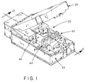
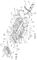
- FIG. 1 An optical fiber connector enclosure 20 is shown in Figure 1 with the improved fiber optic connector 40 of the present invention disposed therein in assembled relation.
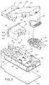
- Figure 2 the connector enclosure 20 and the fiber optic connector 40 are shown in an exploded view which better illustrates the respective parts of the fiber optic connector which are described in greater detail below.
- the connector enclosure 20 includes a main body portion 22 that is generally rectangular in shape but includes a necked-down portion 24 at an outer end thereof as shown in Figure 2. Relatively thick lateral side walls 25 and 26 and a substantially thicker end wall 28 define a space therein for receiving the fiber optic connector 40.
- the fiber optic connector 40 includes a non-disposable portion or member 42 and a disposable portion or member 44, the disposable member having a cover 46.
- An enclosure cover 29 overlies the main body portion 22 of the connector enclosure 20 when the connector 40 is in place.
- Facing slots 31 and 32 are disposed in the respective inner faces of lateral side walls 25 and 26 of the main body portion 22 of the connector enclosure 20.
- the slots 31 and 32 are disposed near the necked-down portion 24 of the main body portion 22 and extend below the upper surface of a base wall 34 of the main body portion.
- a transverse slot 35 in the base wall 34 connects the side slots 31 and 32.
- Projecting forwardly of the transverse slot 35 are a pair of slots 37, each disposed adjacent a respective sidewall 25 and 26.
- the slots 37 each pierce the base wall 34 at their respective intersections with the transverse slot 35.
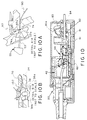
- Disposed forwardly of the slots 37 and generally in alignment therewith are a pair of electrical contacts 38 (Figure 10).
- Each contact 38 includes a washer 38a and a screw 38b ( Figure 10B).
- a base plate 39 covers the bottom of the connector enclosure 22.
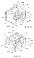
- the non-disposable member 42 of the connector 40 is U-shaped as shown in Figures 3-5 and includes a base 43 with legs 45 extending forwardly from opposite ends of the base.
- the base 43 is substantially thicker than the legs 45.
- the non-disposable member 42 is a plastic molded part and its interior is substantially hollow with the periphery of the base 43 defined by relatively thin opposite side walls 43a, 43b and opposite end walls 45a and 45b.
- An outer end 47 of the base 43 opens into the interior of the member 42.
- a peripheral flange 48 surrounds an opening in the outer end 47 of the hollow base 43.
- Stiffeners 47a are provided between sidewalls 43a,b in the hollow interior of the base 43.
- An angled inner or front wall 49 generally disposed between legs 45 of the U-shaped non-disposable member 42, completes the base 43.
- Legs 45 extend generally transversely from the base 44, in generally parallel alignment, at opposite ends thereof.
- the outer side portions of legs 45 are defined by forward extensions of opposite side walls 43a,b of the base 43 and the end walls 45a,b.
- Respective interior side walls 45c extend forwardly from the front wall 49 of the base 43, to define respective inner side portions of the legs 45.
- Forward end walls 45d enclose the legs 45.
- a forward extension or pad 50 disposed between the respective forward portions of legs 45 and supported by angled side walls 50a and angled top and bottom walls 50b, the walls 50a,b extending forwardly from the front wall 49.
- the walls 50a and 50b project forwardly to define an elevated abutment surface or front face 51 of the pad 50 that is somewhat smaller than the area defined by the pad on the front wall 49.
- Both the front wall 49 of the base 43 and the front face 51 of the pad 50 on the front wall are canted at about 20° from the vertical or 70° from the horizontal when the non-disposable member 42 of the fiber optic connector 40 is positioned in the main body portion 22 of the connector enclosure 20.
- the angle of 20° chosen for the preferred embodiment should be considered illustrative and not limiting.
- the intent is to minimize a reflective component of light at the fiber interface.
- Each opening 52 receives a glass optical fiber 53, which in the preferred embodiment is about 0.0096 inches in diameter (0.0096D), or about 2 to 3 times the diameter of a human hair.
- non-disposable member 42 of the connector 40 is shown lying on its bottom face.
- transverse lateral ribs 56 extend forwardly from the base 43 of the member 42 along the legs 45 to terminate near respective end walls 45d thereof.
- the pad 50 is slightly narrower than the front wall 49 of the base 43. However, on each side of the pad 50, at the front wall 49 of the base 43, inner side wall 45c of each leg 45 of the non-disposable member 42 is notched or stepped to define respective horizontal reference surfaces 57a and 57b and respective vertical reference surfaces 58a and 58b in opposite side walls 45c in the respective inner portions of legs 45.
- the reference surfaces 57a,b and 58a,b are associated with the optical fibers 53 mounted in the openings 52 in the pad 50 and are provided to precisely align the optical fibers 53 in the non-disposable member 42 with their counterparts in the disposable member 44, as well as to constrain respective lateral and vertical motion of the disposable member relative to the non-disposable member.
- each inner sidewall 45c defines a lateral reference surface 57a,b that is generally parallel with its respective inner side wall 45c, but stepped toward its respective outer side wall 45a or 45b.
- Vertical reference surfaces 58a,b extend inwardly from respective upper ends of reference surfaces 57a,b to intersect respective inner side walls 45c generally at a midplane thereof.
- the notches 59 do not extend vertically from the front face 49 of the base 43 to the front ends 45d of the legs 45, but rather are canted towards the outer side walls 45b of the legs from about the mid point of the notch to the front ends of the legs to provide respective tapered guide surfaces 60 in respective outer legs of the non-disposable member 42. Also, the respective intersection of lateral reference surfaces 57a and 57b, vertical reference surfaces 58a and 58b, and the respective inner ends of the canted portions 60 are also rounded to guide the disposable member 44 into the non-disposable member 42 of the connector 40.
- the disposable member 44 of the connector 40 is a molded plastic part having a hollowed-out main body portion 60 of generally trapezoidal shape.
- the hollowed-out main body portion 60 has a rear wall 61 that is longer than a front wall 62, with side walls 63 extending generally transversely from opposite ends of the rear wall 61 to slightly beyond their respective midpoints. At these mid-points, the side walls 63 bend inwardly toward the narrow front wall 62 to define a necked-down portion 64 of the disposable member 44, disposed at a front end of the main body portion 60.
- the main body portion 60 features a double walled construction in which the rear wall 61 and opposite sidewalls 63 include respective inner walls 61a and 63a, which are about .070 inches lower than outer walls 61 and 63.
- the front wall 62 is of single wall construction, but the upper surface thereof coincides with the respective upper surfaces of walls 61a and 63a, for reasons to be described below.
- a base wall 65 of the main body portion 60 features a relatively large central cutout portion 66 which is bisected by a cross member 67.
- Cross member 67 extends from the bottom of the necked-down portion 64 of the main body portion 60 and relatively parallel to the transverse portions of sidewalls 63, terminating about 0.200 inches outside the rear wall 61.
- the height of the cross member 67 approximately equals the height of the inner walls 61a and 63a.
- cross member 67 between the rear wall 61 and the necked-down portion 64 partially defines a pair of openings 68 and 69 in the base wall 65 of the main body portion 60.
- the cross member 67 includes a channel 67a between opposite channel side walls 68a and 69a, which also respectively correspond to the inner walls of the openings 68 and 69.
- Respective outer side walls 68b and 69b extend transversely from the rear wall 61 to the respective inwardly tapered portions of the sidewalls 63 to define one side of the openings 68 and 69, with the forward ends of inner walls 68a and 69a curving outwardly to engage respective side walls 63 at the respective inwardly directed portions thereof to form openings 68 and 69 in the base wall 65.
- Fingers 70 and 71 are generally coincident with base wall 65 and extend inwardly to terminate near the upper end of respective openings 68 and 69.
- Members 73a and 73b project upwardly from the base wall 65 in the necked-down portion 64 of the main body portion 60 to extend slightly above front wall 62 and side walls 63a and are generally aligned with the main portions of respective side walls 68a and 69a of the cross member 67.
- Front wall 62 is relatively thick and is canted at an angle that is complementary to the angle of the front wall 49 of the base 43 on the non-disposable member.
- the upper surface of the front wall 62 is flush with the respective upper surfaces of the inner walls 61a and 63a of the main body portion 60.
- Three centrally located, equally spaced support members 74 project outwardly from the upper end of the front wall 62 and each has defined therein a central slot 75.
- Three discrete plastic optical fibers 80 are associated with a fiber optic cable assembly 76, and are each received in a respective slot 75.
- first lateral reference node 78 At the forward end of a first side wall 63, on an outer face thereof, and generally aligned with front wall 62, is molded a first lateral reference node 78, which is wedge-shaped and generally incompressible. At the forward end and on the outer face of an opposite side wall 63, is molded a second lateral reference node 79, generally compressible, comprising a triangular "crush" rib. Nodes 78 and 79, disposed at opposite ends of the front wall 62 and generally aligned therewith, are complementary with the horizontal reference surfaces 57a,b provided in opposite side walls 45c of the non-disposable member 42.
- each outer side wall 63 on an upper surface thereof, is molded an incompressible vertical reference nodule 63b.
- Each nodule 63b is disposed at an opposite end of the front wall 62 and generally in alignment therewith.
- Vertical reference nodules 63b are complementary to the vertical reference surfaces 58a,b provided in opposite side walls 45c of the non-disposable member 42.
- an integral plastic spring 82 Connected to the outside of the rear wall 61 of the main body portion 60 is an integral plastic spring 82 having a pair of rearwardly extending flexible members 81 disposed on opposite sides of the cross member 67. Flexible members 81 terminate at a forward edge of a spring handle 83. Spring latching members 84 are provided at an inner end of the handle 83.
- a generally L-shaped cover 46 ( Figures 11-13) having a base wall 91, which is inserted between outer walls 61 and 63 to overlie the main body portion 60, resting on the upper surfaces of inner rear wall 61a, inner side walls 63a and front wall 62.
- Overlying members 73a and 73b is a cut out 91a provided on the underside of base wall 91. Cut out 91a provides clearance for the members 73a,b, which protrude slightly above side walls 63a, extending into the cutout 91a.
- An upright leg 95 of the L-shaped cover 46 also supports a rearward projection 96, which overlies the rearward extension of the channel 67 from the rear wall 61 of the main body portion 60.
- a rearward projection 96 At the front end of the cover 46, three centrally located, equally spaced inner projections 97 complement and engage the support members 74 when each optical fiber 80 of the cable assembly 76 has been placed in its respective slot 75.
- Inner projections 97 thus trap and hold the optical fibers 80 in a fixed position for alignment with the complementary optical fibers 53 in the non-disposable member 42.
- extensions 98 Disposed on opposite sides of the projections 97 are extensions 98, each of which have a front face 98a that is generally coplanar with respective front faces 97a on the inner projections 97.
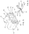
- Both the fiber optic cable assembly 55 ( Figure 6) associated with the non-disposable member 42 of the connector 40 and the fiber optic cable assembly 76 ( Figure 7) associated with the disposable member 44 are multi-strand cable assemblies and include several similar structural elements. However, their differences are significant and those differences offer an important contribution to the effectiveness of the fiber optic connector of the present invention. Accordingly, fiber optic cable assemblies 55 and 76 are discussed separately below.
- the optical cable assembly 55 associated with the non-disposable member 42 of the connector 40 comprises a plurality of elongated, discrete, glass optical fibers 53.
- each of the optical fibers 53 of the preferred embodiment is about 0.0096 inches in diameter (0.0096D).
- a plurality of elongated Kevlar elements 101 are co-extensive with the optical fibers 53 to provide tensile strength to the cable assembly 55 and thus protect the relatively fragile optical fibers 53, and a pair of elongated thermocouple elements 102 coextensive with the optical fibers 53 are included in the cable assembly 55 for temperature measurement.
- the thermocouple elements 102 are metallic.
- the cable assembly 55 is connected to the non-disposable member 42 of the connector 40, as follows.
- optical fibers 53, the Kevlar elements 101 and the thermocouple wires 102 are separated before assembly, with the optical fibers 53 being suitably secured into the openings 52 provided in the front face 51 of the pad 50.
- the optical fibers 53 are then bonded in place with a respective front face 53a of each optical fiber protruding slightly forward of front face 51 of pad 50.
- a suitable potting material is applied to fill the hollow interior of the non-disposable member 42, anchoring the optical fibers 53 in place.
- the front face 51 of the pad 50 is then lapped with a suitable lapping tool that cants as well as smooths the front face and also grinds the respective front face 53a of each optical fiber 53 disposed therein so that it is flush with the front face.
- Both the front face 51 of the pad 50 and the front faces 53a of the optical fibers 53 are canted to a precise angle that is 20° from the vertical as shown in Figure 2. This design also allows the angle to be reduced to at least 15°.
- the non-disposable member 42 of the connector 40 is mounted in the main body portion 22 of the connector enclosure 20.
- the respective side flanges 48a of the peripheral flange 48 are disposed in the slots 31 and 32 provided in the sidewalls 25 and 26 of the main body portion 22.
- a lower flange 48c is received within the slot 35 provided in the base wall 34, and lateral ribs 56 running along legs 45 of the non-disposable member 42 are received in corresponding complementary slots 37 in the base wall.
- a registration nodule 48b ( Figure 5) is provided at the midpoint of each side flange 48a. Nodule 48b extends outwardly thereof and engages opposite edges of a respective slot 31,32 to precisely position the non-disposable member 42 in the enclosure 20. The engagement of the lower flange 48c within the transverse slot 35 defines a precise vertical location for the non-disposable member 42 in the connector enclosure 20. With the non-disposable portion 42 fixedly mounted in the connector enclosure 20, the remaining portions of the cable assembly 55 are connected thereto as follows.
- thermocouple wires 102 can connect to the undersides of contacts 38.
- a suitable channel 25a is provided in the sidewall 25 to enable the Kevlar elements 101 to be drawn away from the cable assembly 55 and bonded to the connector enclosure 20.
- the optical cable assembly 76 ( Figure 7), associated with the disposable member 44 of the connector 40 includes a plurality of elongated, discrete plastic optical fibers 80, each of which is about 0.0046 inches in diameter (0.0046D).
- a plurality of elongated Kevlar elements 101' coextensive with the optical fibers 80 provide tensile strength to the cable assembly 76, and thermocouple wires 102' are included to provide temperature measurements.
- the optical fibers 80 of the disposable member 44 are not limited to the dimensions recited in the preferred embodiment, but should be somewhat smaller in diameter than the optical fibers 53 of the non-disposable member 42 to minimize signal loss at the interface of the optical fibers in connector 40.
- the Kevlar elements 101' are separated from the optical fibers 80, and each optical fiber 80 is secured in a respective slot 75, preferably by bonding it in place.
- the Kevlar elements 101' are drawn into a shallow channel 61a' to be bonded therein:
- the channel 61a' is adjacent the channel 67a, disposed in an upper face of the rear wall 61 of the disposable main body portion 60.
- Thermocouple wires 102' extend along the channel 67a until they reach respective cutout portions 68a' and 69a' provided in the respective sidewalls 68a and 69a of the channel 67a, with a first wire 102a' to be inserted into a pair of openings 70a in the inner end of contacting finger 70 and a second wire 102b' to be inserted into a pair of openings 71a in the inner end of contacting finger 71.
- Thermocouple wires 102a', 102b are threaded through respective openings 70a and 71a and extend to the underside of the disposable member 44, respectively defining electrical contacts 103a and 103b at the underside of the disposable member.
- Projections 73a and 73b provided in the necked-down portion 64 of the main body portion 60, separate the optical fibers 80 as they extend along the channel 67a into the slots 75 so as to avoid undue bending of the optical fibers 80 when they are placed in the slots 75.
- the cover 46 is suitably affixed, preferably by bonding it to the main body portion 60 of the disposable member 44.
- the front faces of the support members 74, and the front faces of the associated optical fibers 80 mounted therein are lapped to produce a smooth angular face 74a for each support member 74 and a smooth, angular, coplanar face 80a for each of the optical fibers 80 of the disposable member 44.
- the lapped angle is complementary to the 20° angle lapped onto the end faces 53a of the optical fibers 53 disposed in the end face 51 of the non-disposable member 42 of the connector 40. Only the end faces 74a of the support members 74 and their associated optical fibers 80 are lapped.
- the inner projections 97 on the cover 46 are not lapped.
- each forward extension 98 does not overlie a corresponding support member, a portion of each forward extension 98 coplanar with the front faces 74a of support members 74 is lapped.
- a forward edge is defined on the extensions 98 that is coplanar with end faces 80a of the optical fibers 80 which are disposed in and slightly forward (0.002") of respective lapped end faces 74a.
- the completed disposable member 44 of the fiber optic connector 40 includes the lapped end faces 80a of the optical fibers 80 and a completely installed cable assembly 76.
- the assembled disposable member 44 can then be inserted into the connector enclosure 20 as follows.
- Forward extensions 98 engage the outer edges of lapped face 51 of the pad 50 to traverse the lapped face as the disposable member 44 is inserted into the connector enclosure 20.
- the respective end faces 53a of the optical fibers 53 mounted in the non-disposable member 42 are both laterally and vertically aligned and fully engaged with the respective end faces 80a of complementary optical fibers 80 mounted in the disposable member 44.
- the contacts 103a and 103b on the disposable member 44 complete electrical contact between the non-disposable member 42 and the disposable member 44, and the latching members 84 of the spring 82 engage complementary latching elements 30a provided in the rear wall 30 of the connector enclosure 20 to secure the disposable member 44 in place in the fully aligned position of the fiber optic connector 40.
- the end faces 53a,80a of the optical fibers 53,80 are parallel to each other, but at an oblique angle with respect to the respective parallel axes thereof. In the preferred embodiment, the respective end faces are each disposed about 20° from the vertical.
- the non-disposable glass (0.0096D) optical fiber 53 is larger in diameter than the disposable plastic (0.0046D) optical fiber 80.
- a ray propagating along the non-disposable optical fiber 53 toward the fiber interface at an angle from its axis will strike the interface, producing a reflected component and a transmitted component of normalized amplitude. Because the angle at the fiber interface is chosen to minimize unwanted reflections and to maximize data transmissions, for virtually all rays within the optimum angle of the fiber interface, the reflections from the fiber interface will not be transmitted along the optical fibers 53,80 but will be propagated into a cladding surrounding them. Since the beveled interface is effective in suppressing reflected signals transmitted along the non-disposable optical fibers 53, it can be made larger than the disposable optical fiber 80 without creating a significant reflected signal.
- the enclosure cover 29 ( Figure 2) is placed on the enclosure 20.
- a rear end 121 of the cover 29 is bonded to the connector enclosure 20 using a suitable adhesive.
- the cover 29 is hinged at 122 with a front cover portion 123 overlying the main body portion 22 of the connector enclosure 20.
- Latching members 124 extend downwardly from the front cover portion 123 to engage the respective inner walls 25 and 26 of the connector enclosure 20 to secure the cover 29 in a closed position on the main body portion 22 of the connector enclosure 20.
- the need to precisely align optical fibers which may be as little as five thousandths of an inch (0.005") in diameter, indicates that the apparatus herein defined for use with a cable assembly having multiple optical fibers would be equally useful in connecting a single optical fiber at the fiber interface of the connector.
- the dimensions of the respective optical fibers mounted on the non-disposable and disposable members of the connector are not limited to the dimensions recited for the preferred embodiment of the present invention.
Landscapes
- Physics & Mathematics (AREA)
- General Physics & Mathematics (AREA)
- Optics & Photonics (AREA)
- Mechanical Coupling Of Light Guides (AREA)
Applications Claiming Priority (6)
| Application Number | Priority Date | Filing Date | Title |
|---|---|---|---|
| US629320 | 1990-12-18 | ||
| US629321 | 1990-12-18 | ||
| US07/629,320 US5130790A (en) | 1990-12-18 | 1990-12-18 | Apparatus for aligning and supporting the optical fibers for an optical fiber cable assembly |
| US07/629,323 US5074638A (en) | 1990-12-18 | 1990-12-18 | Method for joining optical fibers at the fiber interface of a beveled angle fiber optic connector |
| US629323 | 1990-12-18 | ||
| US07/629,321 US5134675A (en) | 1990-12-18 | 1990-12-18 | Beveled angle fiber optic connector |
Publications (2)
| Publication Number | Publication Date |
|---|---|
| EP0491376A2 true EP0491376A2 (de) | 1992-06-24 |
| EP0491376A3 EP0491376A3 (en) | 1993-10-13 |
Family
ID=27417474
Family Applications (1)
| Application Number | Title | Priority Date | Filing Date |
|---|---|---|---|
| EP19910121694 Withdrawn EP0491376A3 (en) | 1990-12-18 | 1991-12-18 | Beveled angle fiber optic connector |
Country Status (2)
| Country | Link |
|---|---|
| EP (1) | EP0491376A3 (de) |
| AU (1) | AU8977991A (de) |
Cited By (2)
| Publication number | Priority date | Publication date | Assignee | Title |
|---|---|---|---|---|
| CN102081203A (zh) * | 2009-11-26 | 2011-06-01 | 富士康(昆山)电脑接插件有限公司 | 线缆连接器组件 |
| CN114486691A (zh) * | 2022-02-16 | 2022-05-13 | 上海纬冉科技有限公司 | 一种便携式能量探测设备及其调试装置 |
Family Cites Families (6)
| Publication number | Priority date | Publication date | Assignee | Title |
|---|---|---|---|---|
| US4645295A (en) * | 1980-02-04 | 1987-02-24 | Allied Corporation | Fiber optic connector |
| JPS58152212A (ja) * | 1982-03-05 | 1983-09-09 | Nec Corp | 光コネクタ |
| US4647149A (en) * | 1983-10-28 | 1987-03-03 | American Hospital Supply Corporation | Attachment of optical fibers to a connector body |
| CA1247957A (en) * | 1983-10-28 | 1989-01-03 | Ronald L. Mccartney | Oximeter |
| US4913514A (en) * | 1988-11-22 | 1990-04-03 | Advanced Optical Systems | Fiber optic connector |
| US4969924A (en) * | 1989-05-18 | 1990-11-13 | General Motors Corporation | Electro-optical connector plug |
-
1991
- 1991-12-17 AU AU89779/91A patent/AU8977991A/en not_active Abandoned
- 1991-12-18 EP EP19910121694 patent/EP0491376A3/en not_active Withdrawn
Cited By (2)
| Publication number | Priority date | Publication date | Assignee | Title |
|---|---|---|---|---|
| CN102081203A (zh) * | 2009-11-26 | 2011-06-01 | 富士康(昆山)电脑接插件有限公司 | 线缆连接器组件 |
| CN114486691A (zh) * | 2022-02-16 | 2022-05-13 | 上海纬冉科技有限公司 | 一种便携式能量探测设备及其调试装置 |
Also Published As
| Publication number | Publication date |
|---|---|
| EP0491376A3 (en) | 1993-10-13 |
| AU8977991A (en) | 1992-06-25 |
Similar Documents
| Publication | Publication Date | Title |
|---|---|---|
| US5074638A (en) | Method for joining optical fibers at the fiber interface of a beveled angle fiber optic connector | |
| US6149315A (en) | Side load resistant buildout | |
| JP2627537B2 (ja) | カセット及びそれを使用する電気コネクタ組立体 | |
| CN108139542B (zh) | 具有线缆保持器的光学组件 | |
| US7512307B2 (en) | Method of making optical connector ferrule, die for making optical connector ferrule, optical connector ferrule made by this method, and optical connector and optical wiring system using the same | |
| US4201444A (en) | Single optical fiber connector | |
| US5134675A (en) | Beveled angle fiber optic connector | |
| JPH09113750A (ja) | ジャックレセプタクル | |
| JPS6323522B2 (de) | ||
| CN108139547A (zh) | 多波导连接器中的光波导定位特征结构 | |
| JPH11326694A (ja) | 光ファイバコネクタ組立体 | |
| KR970003763B1 (ko) | 직접 광학 소자 및 그 제조방법 | |
| JPS5816213A (ja) | 電気接点と光フアイバを同時に相互接続するためのコネクタ | |
| KR19990076636A (ko) | 광전자 장치용 소켓 | |
| JPH11160563A (ja) | メカニカルスプライス型光コネクタ及びその製造方法 | |
| US20190377138A1 (en) | Dual spring multi-fiber optic connector | |
| CN108351472A (zh) | 减尘光学连接器 | |
| EP1442327B1 (de) | Ausrichtungsstiftbaugruppe für faseroptische verbinder | |
| US6220763B1 (en) | Optical fiber buildout system | |
| EP0560796B1 (de) | Faseroptische kopplungsvorrichtung und verfahren | |
| CA1279176C (en) | Optical fiber termination device having cutting means | |
| US5130790A (en) | Apparatus for aligning and supporting the optical fibers for an optical fiber cable assembly | |
| US6939057B2 (en) | Optical coupling unit and method for inserting optical wave guides into an optical coupling unit | |
| JPH08292344A (ja) | 光ファイバの保持構造、及び光コネクタ | |
| EP0156066B1 (de) | Oximeter |
Legal Events
| Date | Code | Title | Description |
|---|---|---|---|
| PUAI | Public reference made under article 153(3) epc to a published international application that has entered the european phase |
Free format text: ORIGINAL CODE: 0009012 |
|
| AK | Designated contracting states |
Kind code of ref document: A2 Designated state(s): BE CH DE DK ES FR GB GR IT LI NL SE |
|
| PUAL | Search report despatched |
Free format text: ORIGINAL CODE: 0009013 |
|
| AK | Designated contracting states |
Kind code of ref document: A3 Designated state(s): BE CH DE DK ES FR GB GR IT LI NL SE |
|
| 17P | Request for examination filed |
Effective date: 19940129 |
|
| STAA | Information on the status of an ep patent application or granted ep patent |
Free format text: STATUS: THE APPLICATION IS DEEMED TO BE WITHDRAWN |
|
| 18D | Application deemed to be withdrawn |
Effective date: 19950701 |