EP0491102A1 - Golf training device - Google Patents
Golf training device Download PDFInfo
- Publication number
- EP0491102A1 EP0491102A1 EP90313966A EP90313966A EP0491102A1 EP 0491102 A1 EP0491102 A1 EP 0491102A1 EP 90313966 A EP90313966 A EP 90313966A EP 90313966 A EP90313966 A EP 90313966A EP 0491102 A1 EP0491102 A1 EP 0491102A1
- Authority
- EP
- European Patent Office
- Prior art keywords
- golf
- golf ball
- driving
- wall
- driving platform
- Prior art date
- Legal status (The legal status is an assumption and is not a legal conclusion. Google has not performed a legal analysis and makes no representation as to the accuracy of the status listed.)
- Withdrawn
Links
Images


Classifications
-
- A—HUMAN NECESSITIES
- A63—SPORTS; GAMES; AMUSEMENTS
- A63B—APPARATUS FOR PHYSICAL TRAINING, GYMNASTICS, SWIMMING, CLIMBING, OR FENCING; BALL GAMES; TRAINING EQUIPMENT
- A63B69/00—Training appliances or apparatus for special sports
- A63B69/36—Training appliances or apparatus for special sports for golf
- A63B69/3691—Golf courses; Golf practising terrains having a plurality of driving areas, fairways, greens
- A63B69/3694—Golf courses; Golf practising terrains having a plurality of driving areas, fairways, greens for driving only
-
- A—HUMAN NECESSITIES
- A63—SPORTS; GAMES; AMUSEMENTS
- A63B—APPARATUS FOR PHYSICAL TRAINING, GYMNASTICS, SWIMMING, CLIMBING, OR FENCING; BALL GAMES; TRAINING EQUIPMENT
- A63B57/00—Golfing accessories
- A63B57/0006—Automatic teeing devices
Definitions
- the invention relates to a golf training device to be provided on a golf driving range, and more particularly to a golf training device which not only improves a golfer's driving force, but also allows the golfer to practice hitting the golf ball at different driving angles and to improve the accuracy of the direction of his drives.
- Conventional golf driving ranges usually comprise of a vast, open field equipped with distance markers, and tees provided on a driving platform.
- the objective of a golfer practicing his golf drives is to drive the golf ball as far as he can from the driving platform.
- the length of the driving range must be sufficient to accommodate very long drives.
- Another disadvantage of conventional driving ranges is that it is difficult to collect the golf balls scattered on the driving range. Still another disadvantage of conventional driving ranges is that they do not have provisions for minimizing the movement required of golfers when replacing golf balls on the driving platform.
- a golf training device for a golf driving range, comprising: driving platform means positionable, in use, at one end of said driving range; a wall positionable, in use, on said driving range a predetermined distance from said driving platform means, with a front surface of said wall facing said driving platform means; a padding member made of a soft, shock absorbent material and mounted on said front surface of said wall, said padding member having a plurality of horizontal angle graduations for indicating the angle at which a golf ball has been driven from said driving platform means, said padding member further having a vertical reference line alignable, in use, with said driving platform means; and velocity sensing means mounted on said driving platform means for measuring the initial velocity of a golf ball driven from said driving platform means.
- the golf training device of the present invention may be installed on a golf driving range and used to improve a golfer's driving force and give an indication of the angle at which the golf ball was driven from the driving platform and of the direction of the projectile path of the golf ball.
- a rough approximation of the range of the golf ball can be determined by using appropriate projectile formulas even though the golf ball does not complete its projectile path because of the wall.
- a horizontal boundary plate obstruction may be provided on top of the wall to prevent golf balls from going over the wall.
- the golf training device may further comprise a first conveyer belt located across the width of the wall for collecting golf balls bouncing off the wall, and a second conveyer belt transverse to the first conveyor belt for conveying golf balls collected by the first conveyer belt to the driving platform means to facilitate collection of the golf balls scattered on the driving range.
- the driving platform means may comprise a horizontal platform member; means for supplying golf balls including a container mounted on the platform member for receiving golf balls, and an elongate and inclined support channel extending beneath the platform member from the container to a discharge end for discharging golf balls one after the other; an ejecting device including a top plate normally biased upwards to be flush with the platform member and a transverse cover plate connected to the top plate and normally blocking the open discharge end of the support channel, the top plate being displaceable below the discharge end to move the cover plate past the discharge end to permit movement of a golf ball out of the discharge end and onto the top plate; and means for preventing more than one golf ball from moving out of the discharge end when the top plate is lowered.
- the driving platform means minimizes the movement required of golfers when replacing golf balls on the driving platform.
- a golf training board for a golf driving range comprising: a wall positionable, in use, on said driving range and having a front surface; and a padding member made of a soft, shock absorbent material and mounted on said front surface of said wall, said padding member having a plurality of horizontal angle graduations for indicating the angle at which a golf ball has been driven, said padding member further having at least one vertical reference line for indicating the direction of the projectile path of the golf ball.
- the golf training device includes a wall 10 that is separated by a predetermined distance from a plurality of individual driving platform means 7.
- the front surface of the wall 10 is covered by a graduated padded member 20 made of a soft, shock absorbent material.
- the padded member 20 is marked with horizontal angle graduations 21 (such as from 15 degrees to 55 degrees, in increments of 5 degrees).
- the angle graduations 21 serve to indicate the angle at which a golf ball was driven from one of the platform means 7.
- the padded member 20 is further marked with a plurality of vertical reference lines 22 which are aligned with the driving platform means 7.
- a horizontal boundary plate obstruction 30 is provided on top of the wall 10.
- a wind vane 31 and a wind velocity counter 32 are mounted on top of the plate obstruction 30.
- the angle graduations 21 must be arranged according to the distance of the wall 10 from the driving platform means 7.
- the 25 degree, 30 degree, and 45 degree graduations are located at different heights when the wall 10 is placed at position L, position II, or position III.
- the wall 10 is spaced by a minimum safe distance x from the driving platform means 7. The minimum distance x should be set such that the golf balls are unlikely to hit a golfer when they bounce off the wall 10.
- the plate obstruction 30 Whenever a golf ball has been driven at an angle in excess of the predetermined maximum angle (such as 55 degrees), the plate obstruction 30 will block further movement of the golf ball.
- One of the advantages of using the preferred embodiment of a golf training device according to the present invention is that the size of the driving range can be reduced. A rough approximation of the range of the golf ball can be determined by using appropriate projectile formulas even if the golf ball does not complete its projectile path.
- the Y-axis component (Vy) of the velocity of the golf ball at any time (t) is equal to ( Vo sin ⁇ - gt ).
- Vy is equal to zero, and, thus, the time to reach the highest point is equal to ( Vo sin ⁇ / g ).
- the total time of flight of the golf ball (Tt) is twice the time to reach the highest point.
- the range of the golf ball can thus be determined in terms of the initial velocity of the golf ball and its driving angle.
- the driving angle of the golf ball can be determined by simply noting the angle graduation 21 at which the golf ball struck the graduated padded member 20.
- an electrical velocity sensing means 40 is mounted on each of the individual platform means 7 to measure the initial velocity (Vo) of the golf ball. The range of the golf ball can then be computed by using the above disclosed formulas.
- An electrical angle measuring means 40' can be similarly mounted on each of the individual platform means 7 adjacent to the velocity sensing means 40. The angle measuring means 40' serves as an additional driving angle indicating means for the golf ball.
- the preferred embodiment can be used as a training means to increase the driving force to thereby increase the initial velocity of the golf ball, or as a training means to drive the golf ball at different driving angles. Note that, for a given initial velocity, the range of the golf ball is at a maximum if the golf ball is driven at an angle of 45 degrees. Angles greater than or less than 45 degrees would yield a shorter range.
- a golfer can get an indication of the direction of the projectile path of the golf ball by simply noting the point at which the golf ball struck the graduated padded member 20 relative to the reference lines 22.
- the golfer may practice the accuracy of the direction of his drives. This, aside from allowing the golfer to improve his driving force and to practice driving the golf ball at different driving angles, the preferred embodiment also allows him to practice the accuracy of the direction of his drives.
- a wide conveyer belt 50 extending along the width of the wall 10, is provided on the portion of the golf driving range immediately in front of the wall 10. Golf balls collected by the conveyer belt 50 are transported to another conveyer belt 60 disposed transverse to the conveyer belt 50. The conveyer belt 60 moves in a direction away from the wall 10 and towards the driving platform means 7. Golf balls on the conveyer belt 60 are then collected for reuse.
- the preferred embodiment incorporates means for minimizing movement of the golfer when replenishing golf balls on a horizontal platform member 70 of the platform means 7.
- a golf ball is placed on a top plate 71 of an ejecting device of the platform means 7.
- the bottom surface of the top plate 71 is connected to and covers the top end of a vertical pipe 72.
- the pipe 72 is telescopically connected to a sunken second vertical pipe 74.
- a spring member 73 is disposed between the top plate 71 and the top end of the pipe 74. The spring member 73 surrounds the outer periphery of the pipe 72 and biases the top plate 71 to be flush with the platform member 70.
- the pipe 74 is formed with a predetermined number of longitudinal slits 740 extending in an axial direction.
- the bottom end of the pipe 72 is provided with a predetermined number of ear projections 720 extending into the longitudinal slits 740.
- the ear projections 720 guide the movement of the pipe 72 relative to the pipe 74 and prevent the disengagement of the pipe 72 from the pipe 74
- a downwardly extending cover plate 710 extends from the top plate 71 near the leftmost edge thereof.
- the cover plate 710 controls the passage of a lowest golf ball (a) disposed adjacent an open discharge end of an elongated and inclined support channel 81 of a golf ball supplying device 80.
- the support channel 81 is disposed beneath the platform member 70.
- the other end of the support channel 81 communicates with a container 82 mounted on the platform member 70 and filled with golf balls.
- the lower portion of the support channel 81 is provided with a guide slot 811 which is spaced from the cover plate 710 by a distance slightly greater than the diameter of one golf ball.
- a vertical fulcrum post 75 is provided adjacent the pipe 74 to the right of the support channel 81.
- a horizontal lever member 76 is supported by the fulcrum post 75.
- One end of the lever member 76 is rigidly connected to an upwardly extending actuating post 77.
- One end of an upwardly extending elongated ball obstructing piece 78 is hinged to the other end of the lever member 76.
- a small portion of the ball obstructing piece 78 normally extends into the guide slot 811 of the support channel 81.
- a spring member 79 has two ends respectively connected to the fulcrum post 75 and to the lever member 76 to bias the lever member 76 in a normal, substantially horizontal position.
- the spring member 73 urges the top plate 71 to be flush with the platform member 70.
- the cover plate 710 blocks the open discharge end of the support channel 81 to prevent passage of the golf ball (a).
- a golf club is used to exert a downward pressing force on the top plate 71, thereby causing the top plate 71 and the pipe 72 to move downwards against the action of the spring member 73. Further movement of the top plate 71 in this direction causes the cover plate 710 to move past the open discharge end of the support channel 81 and allows the golf ball (a) to roll onto the top plate 71.
- the top plate 71 depresses the extreme top end of the actuating post 77. This causes the lever member 76 to pivot on the fulcrum post 75 to thereby allow the ball obstructing piece 78 to fully project into the support channel 81 through the guide slot 811 (Refer to Figure 5). This permits the ball obstructing piece 78 to block further advancement of the succeeding golf ball (b). Thus, only golf ball (a) is allowed to roll out of the support channel 81 when the cover plate 710 moves past the open discharge end of the support channel 81.
- the spring member 73 expands to once more urge the top plate 71 to be flush with the platform means 7.
- the lever member 76 returns to its normal, substantially horizontal position by the action of the spring member 79.
- the ball obstructing piece 78 is retracted from the support channel 81, thereby allowing the advancement of golf balls inside the support channel 81 (i.e., golf ball (b) advances to the former position of golf ball (a)).
Landscapes
- Health & Medical Sciences (AREA)
- General Health & Medical Sciences (AREA)
- Physical Education & Sports Medicine (AREA)
- Golf Clubs (AREA)
Abstract
A golf training device is for use on a golf driving range and includes a driving platform (7) positioned at one end of the driving range and a wall (10) positioned on the driving range a predetermined distance from the driving platform (7). The wall (10) has a front surface facing the driving platform (7) and covered by a padding member (20) made of a soft, shock absorbent material. The padding member (20) has several horizontal angle graduations (21) for indicating the angle at which a golf ball has been driven from the driving platform (7), and a vertical reference line (22) aligned with the driving platform (7) for indicating the direction of the projectile path of the golf ball. A velocity sensor (40) is mounted on the driving platform (7) for measuring the initial velocity of the golf ball driven from the driving platform (7). A rough approximation of the range of the golf ball can then be determined by using appropriate projectile formulas even though the golf ball does not complete its projectile path because it hits the wall (10).
Description
- The invention relates to a golf training device to be provided on a golf driving range, and more particularly to a golf training device which not only improves a golfer's driving force, but also allows the golfer to practice hitting the golf ball at different driving angles and to improve the accuracy of the direction of his drives.
- Conventional golf driving ranges usually comprise of a vast, open field equipped with distance markers, and tees provided on a driving platform. The objective of a golfer practicing his golf drives is to drive the golf ball as far as he can from the driving platform. Thus, the length of the driving range must be sufficient to accommodate very long drives.
- While conventional driving ranges permit the golfer to improve his driving force, they do not give an indication of the angle at which the golf ball was driven from the driving platform. Furthermore, the golfer has no indication of the direction of the projectile path of the golf ball. Thus, the golfer cannot improve the angular accuracy of his golf drives.
- Another disadvantage of conventional driving ranges is that it is difficult to collect the golf balls scattered on the driving range. Still another disadvantage of conventional driving ranges is that they do not have provisions for minimizing the movement required of golfers when replacing golf balls on the driving platform.
- According to a first aspect of the present invention, there is provided a golf training device for a golf driving range, comprising: driving platform means positionable, in use, at one end of said driving range; a wall positionable, in use, on said driving range a predetermined distance from said driving platform means, with a front surface of said wall facing said driving platform means; a padding member made of a soft, shock absorbent material and mounted on said front surface of said wall, said padding member having a plurality of horizontal angle graduations for indicating the angle at which a golf ball has been driven from said driving platform means, said padding member further having a vertical reference line alignable, in use, with said driving platform means; and velocity sensing means mounted on said driving platform means for measuring the initial velocity of a golf ball driven from said driving platform means.
- The golf training device of the present invention may be installed on a golf driving range and used to improve a golfer's driving force and give an indication of the angle at which the golf ball was driven from the driving platform and of the direction of the projectile path of the golf ball.
- A rough approximation of the range of the golf ball can be determined by using appropriate projectile formulas even though the golf ball does not complete its projectile path because of the wall.
- A horizontal boundary plate obstruction may be provided on top of the wall to prevent golf balls from going over the wall.
- The golf training device may further comprise a first conveyer belt located across the width of the wall for collecting golf balls bouncing off the wall, and a second conveyer belt transverse to the first conveyor belt for conveying golf balls collected by the first conveyer belt to the driving platform means to facilitate collection of the golf balls scattered on the driving range.
- The driving platform means may comprise a horizontal platform member; means for supplying golf balls including a container mounted on the platform member for receiving golf balls, and an elongate and inclined support channel extending beneath the platform member from the container to a discharge end for discharging golf balls one after the other; an ejecting device including a top plate normally biased upwards to be flush with the platform member and a transverse cover plate connected to the top plate and normally blocking the open discharge end of the support channel, the top plate being displaceable below the discharge end to move the cover plate past the discharge end to permit movement of a golf ball out of the discharge end and onto the top plate; and means for preventing more than one golf ball from moving out of the discharge end when the top plate is lowered. The driving platform means minimizes the movement required of golfers when replacing golf balls on the driving platform.
- According to a further aspect of the present invention, there is provided a golf training board for a golf driving range, comprising: a wall positionable, in use, on said driving range and having a front surface; and a padding member made of a soft, shock absorbent material and mounted on said front surface of said wall, said padding member having a plurality of horizontal angle graduations for indicating the angle at which a golf ball has been driven, said padding member further having at least one vertical reference line for indicating the direction of the projectile path of the golf ball.
- Other features and advantages of the present invention will become apparent from the following detailed description of a preferred non-limiting embodiment with reference to the accompanying drawings, of which:-
- Figure 1 is a front view of the preferred embodiment of a golf training device according to the present invention;
- Figure 2 is a side view of the golf training device shown in Figure 1;
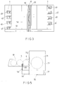
- Figure 3 is a top view of the golf training device shown in Figure 1;
- Figure 4 is a partly sectional view of a driving platform means of the golf training device of Figure 1; and
- Figure 5 is a top view of the driving platform means shown in Figure 4.
- Referring to Figure 1, the preferred embodiment of a golf training device according to the present invention is to be provided on a golf driving range. The golf training device includes a
wall 10 that is separated by a predetermined distance from a plurality of individual driving platform means 7. The front surface of thewall 10 is covered by a graduated paddedmember 20 made of a soft, shock absorbent material. Thepadded member 20 is marked with horizontal angle graduations 21 (such as from 15 degrees to 55 degrees, in increments of 5 degrees). Theangle graduations 21 serve to indicate the angle at which a golf ball was driven from one of the platform means 7. The paddedmember 20 is further marked with a plurality ofvertical reference lines 22 which are aligned with the driving platform means 7. A horizontalboundary plate obstruction 30 is provided on top of thewall 10. Awind vane 31 and awind velocity counter 32 are mounted on top of theplate obstruction 30. - Because the golf balls driven towards the
wall 10 travel in a projectile path, theangle graduations 21 must be arranged according to the distance of thewall 10 from the driving platform means 7. Referring to Figure 2, the 25 degree, 30 degree, and 45 degree graduations are located at different heights when thewall 10 is placed at position L, position II, or position III. Thewall 10 is spaced by a minimum safe distance x from the driving platform means 7. The minimum distance x should be set such that the golf balls are unlikely to hit a golfer when they bounce off thewall 10. - Whenever a golf ball has been driven at an angle in excess of the predetermined maximum angle (such as 55 degrees), the
plate obstruction 30 will block further movement of the golf ball. - One of the advantages of using the preferred embodiment of a golf training device according to the present invention is that the size of the driving range can be reduced. A rough approximation of the range of the golf ball can be determined by using appropriate projectile formulas even if the golf ball does not complete its projectile path.
- The range R of the golf ball is equal to the product of the initial velocity of the golf ball (Vo), the cosine of the angle (ϑ) at which the golf ball is driven, and the total time of flight (Tt) of the golf ball (


- (The preceding formulas apply to vacuum conditions and, thus, only rough approximations of the actual range of the golf ball can be established. These formulas do not take into consideration several weather parameters, such as the wind velocity, which normally affect the projectile path of the golf ball).
- The driving angle of the golf ball can be determined by simply noting the
angle graduation 21 at which the golf ball struck the graduated paddedmember 20. Referring to Figure 3, an electrical velocity sensing means 40 is mounted on each of the individual platform means 7 to measure the initial velocity (Vo) of the golf ball. The range of the golf ball can then be computed by using the above disclosed formulas. An electrical angle measuring means 40' can be similarly mounted on each of the individual platform means 7 adjacent to the velocity sensing means 40. The angle measuring means 40' serves as an additional driving angle indicating means for the golf ball. - Accordingly, the preferred embodiment can be used as a training means to increase the driving force to thereby increase the initial velocity of the golf ball, or as a training means to drive the golf ball at different driving angles. Note that, for a given initial velocity, the range of the golf ball is at a maximum if the golf ball is driven at an angle of 45 degrees. Angles greater than or less than 45 degrees would yield a shorter range.
- Referring once more to Figure 1, a golfer can get an indication of the direction of the projectile path of the golf ball by simply noting the point at which the golf ball struck the graduated padded
member 20 relative to thereference lines 22. By finding a target point on or about analigned reference line 22, the golfer may practice the accuracy of the direction of his drives. This, aside from allowing the golfer to improve his driving force and to practice driving the golf ball at different driving angles, the preferred embodiment also allows him to practice the accuracy of the direction of his drives. - Referring to Figure 3, in order to facilitate the collection of golf balls which bounce off the
wall 10, awide conveyer belt 50, extending along the width of thewall 10, is provided on the portion of the golf driving range immediately in front of thewall 10. Golf balls collected by theconveyer belt 50 are transported to anotherconveyer belt 60 disposed transverse to theconveyer belt 50. Theconveyer belt 60 moves in a direction away from thewall 10 and towards the driving platform means 7. Golf balls on theconveyer belt 60 are then collected for reuse. - As shown in Figure 4, the preferred embodiment incorporates means for minimizing movement of the golfer when replenishing golf balls on a
horizontal platform member 70 of the platform means 7. When the preferred embodiment is in use, a golf ball is placed on atop plate 71 of an ejecting device of the platform means 7. The bottom surface of thetop plate 71 is connected to and covers the top end of avertical pipe 72. Thepipe 72 is telescopically connected to a sunken secondvertical pipe 74. A spring member 73 is disposed between thetop plate 71 and the top end of thepipe 74. The spring member 73 surrounds the outer periphery of thepipe 72 and biases thetop plate 71 to be flush with theplatform member 70. Thepipe 74 is formed with a predetermined number oflongitudinal slits 740 extending in an axial direction. The bottom end of thepipe 72 is provided with a predetermined number ofear projections 720 extending into thelongitudinal slits 740. Theear projections 720 guide the movement of thepipe 72 relative to thepipe 74 and prevent the disengagement of thepipe 72 from thepipe 74
A downwardly extendingcover plate 710 extends from thetop plate 71 near the leftmost edge thereof. Thecover plate 710 controls the passage of a lowest golf ball (a) disposed adjacent an open discharge end of an elongated andinclined support channel 81 of a golfball supplying device 80. Thesupport channel 81 is disposed beneath theplatform member 70. The other end of thesupport channel 81 communicates with acontainer 82 mounted on theplatform member 70 and filled with golf balls. The lower portion of thesupport channel 81 is provided with aguide slot 811 which is spaced from thecover plate 710 by a distance slightly greater than the diameter of one golf ball. - A
vertical fulcrum post 75 is provided adjacent thepipe 74 to the right of thesupport channel 81. Ahorizontal lever member 76 is supported by thefulcrum post 75. One end of thelever member 76 is rigidly connected to an upwardly extending actuatingpost 77. One end of an upwardly extending elongatedball obstructing piece 78 is hinged to the other end of thelever member 76. A small portion of theball obstructing piece 78 normally extends into theguide slot 811 of thesupport channel 81. Aspring member 79 has two ends respectively connected to thefulcrum post 75 and to thelever member 76 to bias thelever member 76 in a normal, substantially horizontal position. - During initial conditions, the spring member 73 urges the
top plate 71 to be flush with theplatform member 70. Thecover plate 710 blocks the open discharge end of thesupport channel 81 to prevent passage of the golf ball (a). In order to move the golf ball onto thetop plate 71, a golf club is used to exert a downward pressing force on thetop plate 71, thereby causing thetop plate 71 and thepipe 72 to move downwards against the action of the spring member 73. Further movement of thetop plate 71 in this direction causes thecover plate 710 to move past the open discharge end of thesupport channel 81 and allows the golf ball (a) to roll onto thetop plate 71. - Prior to the release of the golf ball (a) from the
support channel 81, thetop plate 71 depresses the extreme top end of the actuatingpost 77. This causes thelever member 76 to pivot on thefulcrum post 75 to thereby allow theball obstructing piece 78 to fully project into thesupport channel 81 through the guide slot 811 (Refer to Figure 5). This permits theball obstructing piece 78 to block further advancement of the succeeding golf ball (b). Thus, only golf ball (a) is allowed to roll out of thesupport channel 81 when thecover plate 710 moves past the open discharge end of thesupport channel 81. - When the
top plate 71 is released, the spring member 73 expands to once more urge thetop plate 71 to be flush with the platform means 7. Thelever member 76 returns to its normal, substantially horizontal position by the action of thespring member 79. Theball obstructing piece 78 is retracted from thesupport channel 81, thereby allowing the advancement of golf balls inside the support channel 81 (i.e., golf ball (b) advances to the former position of golf ball (a)).
Claims (10)
- A golf training device for a golf driving range, comprising:
driving platform means (7) positionable, in use, at one end of said driving range;
a wall (10) positionable, in use, on said driving range a predetermined distance from said driving platform means (7), with a front surface of said wall (10) facing said driving platform means (7);
a padding member (20) made of a soft, shock absorbent material and mounted on said front surface of said wall (10), said padding member (20) having a plurality of horizontal angle graduations (21) for indicating the angle at which a golf ball has been driven from said driving platform means (7), said padding member (20) further having a vertical reference line (22) alignable, in use, with said driving platform means (7); and
velocity sensing means (40) mounted on said driving platform means (7) for measuring the initial velocity of a golf ball driven from said driving platform means (7). - The golf training device as claimed in claim 1, wherein said wall (10) has at its top end a horizontal boundary plate obstruction (30) for preventing golf balls from going over said wall (10).
- The golf training device as claimed in claim 1 or 2, further comprising angle measuring means (40') mounted on said driving platform means (7) for serving as additional means for measuring the angle at which a golf ball is driven from said driving platform means (7).
- The golf training device as claimed in any one of claims 1 to 3, further comprising a first conveyer belt (50) located across the width of said wall (10) for collecting golf balls bouncing off said wall (10), and a second conveyer belt (60) transverse to said first conveyer belt (50) for conveying golf balls collected by said first conveyer belt (50) to said driving platform means (7) to facilitate the collection of golf balls.
- The golf training device as claimed in any one of claims 1 to 4, wherein said driving platform means (7) comprises:
a horizontal platform member (70);
means for supplying golf balls (80) including a container (82) mounted on said platform member (70) for receiving golf balls, and an elongate and inclined support channel (81) extending beneath said platform member (70) from said container (82) to a discharge end for discharging golf balls one after the other;
an ejecting device including a tap plate (71) normally biased upwards to be flush with said platform member (70) and a transverse cover plate (710) connected to said top plate (71) and normally blocking said discharge end of said support channel (81), said top plate (71) being displaceable to below said discharge end to move said cover plate (710) past said discharge end to permit movement of a golf ball (a) out of said discharge end and onto said top plate (71); and
means, associated with said ejecting device, for preventing more than one golf ball from moving out of said discharge end when said top plate (71) is lowered. - The golf training device as claimed in claim 5, wherein said ejecting device further comprises:
a first vertical member (72) disposed beneath said platform member (70) and having a top end connected to and covered by said top plate (71);
a second vertical member (74) having a top end telescopically receiving the bottom end of said first vertical member (72); and
biasing means (73) surrounding the outer periphery of said first member (72) and disposed between said top plate (71) and said second member (74) to urge said top plate (71) to be flush with said platform member (70). - The golf training device as claimed in claim 6, wherein said bottom end of said first vertical member (72) is provided with at least one outward radial ear projection (720), said second vertical member (74) has at least one longitudinal slit (740) extending in an axial direction, and each of said ear projections (720) projects into a respective one of said longitudinal slits (740) to telescopically connect together said first and second vertical members (72, 74).
- The golf training device as claimed in claim 5, 6 or 7, wherein said golf ball movement preventing means comprises:
a fulcrum means (75) disposed adjacent to said ejecting device;
a lever means including a horizontal lever member (76) supported by said fulcrum means (75), a first upwardly extending member (77) rigidly connected to one end of said lever member (76), and a second upwardly extending member (78) hinged to the other end of said lever member (76);
said support channel (81) having a guide slot (811) spaced from said discharge end by a distance slightly greater than the diameter of one golf ball; and
biasing means (79) connected to said fulcrum means (75) and said lever member (76) to bias said lever member (76) to rest in a substantially horizontal position;
the arrangement being such that, whenever said top plate (71) is lowered, said top plate (71) depresses said first upwardly extending member (77) to cause said lever member (76) to pivot about said fulcrum means (75), thereby to cause said second upwardly extending member (78) to project far enough into said guide slot (811) to prevent discharge of golf balls (b) upstream of said guide slot (811). - A golf training board for a golf driving range, comprising:
a wall (10) positionable, in use, on said driving range and having a front surface; and
a padding member (20) made of a soft, shock absorbent material and mounted on said front surface of said wall (10), said padding member (20) having a plurality of horizontal angle graduations (21) for indicating the angle at which a golf ball has been driven, said padding member (20) further having at least one vertical reference line (22) for indicating the direction of the projectile path of the golf ball. - The golf training board as claimed in claim 9, wherein said wall (10) has at its top end a horizontal boundary plate obstruction (30) for preventing golf balls from going over said wall (10).
Priority Applications (2)
| Application Number | Priority Date | Filing Date | Title |
|---|---|---|---|
| AU68177/90A AU614923B3 (en) | 1990-12-19 | 1990-12-18 | Golf training device |
| EP90313966A EP0491102A1 (en) | 1990-12-19 | 1990-12-19 | Golf training device |
Applications Claiming Priority (1)
| Application Number | Priority Date | Filing Date | Title |
|---|---|---|---|
| EP90313966A EP0491102A1 (en) | 1990-12-19 | 1990-12-19 | Golf training device |
Publications (1)
| Publication Number | Publication Date |
|---|---|
| EP0491102A1 true EP0491102A1 (en) | 1992-06-24 |
Family
ID=8205661
Family Applications (1)
| Application Number | Title | Priority Date | Filing Date |
|---|---|---|---|
| EP90313966A Withdrawn EP0491102A1 (en) | 1990-12-19 | 1990-12-19 | Golf training device |
Country Status (2)
| Country | Link |
|---|---|
| EP (1) | EP0491102A1 (en) |
| AU (1) | AU614923B3 (en) |
Citations (7)
| Publication number | Priority date | Publication date | Assignee | Title |
|---|---|---|---|---|
| US1598971A (en) * | 1924-12-11 | 1926-09-07 | Edward H Kenyon | Golf-teeing machine |
| US2234814A (en) * | 1939-09-06 | 1941-03-11 | Willis N Weaver | Golf practice target |
| US2450206A (en) * | 1945-10-01 | 1948-09-28 | James F Shouse | Golf teeing apparatus |
| US3602506A (en) * | 1968-12-06 | 1971-08-31 | Joseph Arthur Gentiluomo | Golf range |
| GB1377605A (en) * | 1971-11-01 | 1974-12-18 | Christophers J R | Apparatus for simulating the playing of golf strokes |
| FR2605525A1 (en) * | 1986-10-27 | 1988-04-29 | Minnesota Mining Mfg France | Indoor training assembly for practising golf |
| FR2625442A1 (en) * | 1987-12-31 | 1989-07-07 | Azerad Pierre | Device for supplying golf balls onto a practice area |
Family Cites Families (1)
| Publication number | Priority date | Publication date | Assignee | Title |
|---|---|---|---|---|
| AU1170988A (en) * | 1987-02-12 | 1988-08-18 | Cooke, Martyn | A target device |
-
1990
- 1990-12-18 AU AU68177/90A patent/AU614923B3/en not_active Ceased
- 1990-12-19 EP EP90313966A patent/EP0491102A1/en not_active Withdrawn
Patent Citations (7)
| Publication number | Priority date | Publication date | Assignee | Title |
|---|---|---|---|---|
| US1598971A (en) * | 1924-12-11 | 1926-09-07 | Edward H Kenyon | Golf-teeing machine |
| US2234814A (en) * | 1939-09-06 | 1941-03-11 | Willis N Weaver | Golf practice target |
| US2450206A (en) * | 1945-10-01 | 1948-09-28 | James F Shouse | Golf teeing apparatus |
| US3602506A (en) * | 1968-12-06 | 1971-08-31 | Joseph Arthur Gentiluomo | Golf range |
| GB1377605A (en) * | 1971-11-01 | 1974-12-18 | Christophers J R | Apparatus for simulating the playing of golf strokes |
| FR2605525A1 (en) * | 1986-10-27 | 1988-04-29 | Minnesota Mining Mfg France | Indoor training assembly for practising golf |
| FR2625442A1 (en) * | 1987-12-31 | 1989-07-07 | Azerad Pierre | Device for supplying golf balls onto a practice area |
Also Published As
| Publication number | Publication date |
|---|---|
| AU6817790A (en) | 1991-09-12 |
| AU614923B3 (en) | 1991-07-24 |
Similar Documents
| Publication | Publication Date | Title |
|---|---|---|
| US4872687A (en) | Putting tutor | |
| US4089057A (en) | Method and device for measuring jump-lengths on a ski-jump | |
| US5303924A (en) | Golf game simulating apparatus and method | |
| US5209483A (en) | Transducing and analyzing forces for instrumented sporting devices and the like | |
| US5616085A (en) | Golf swing training device | |
| US4832344A (en) | Golf club | |
| US5792015A (en) | Putting aid | |
| US4864854A (en) | Golfer's wind indicator and club selection assistance device | |
| US7987693B2 (en) | Method and device for automated electronic green speed measurement | |
| US6607448B2 (en) | Elevated golf putting practice device | |
| US6110052A (en) | Apparatus and method for analyzing bowling technique | |
| US5485994A (en) | Baseball tossup device | |
| EP0491102A1 (en) | Golf training device | |
| US20150182838A1 (en) | Golf putting practice machine having laser pointer | |
| US5214491A (en) | Apparatus and method for determining the position of a football during a football game | |
| US3142488A (en) | Putting mat with golf ball dispensing means | |
| CA2032906A1 (en) | Golf training device | |
| EP0002921B1 (en) | Improvements in automatic golf teeing devices | |
| US3147980A (en) | Practice golf tee and means for delivering balls thereto | |
| US5417427A (en) | Golf training device | |
| US5580318A (en) | Golf ball delivery system | |
| US3239227A (en) | Electrical target apparatus for surface projectile game | |
| US4009883A (en) | Ball game practicing device | |
| US3299692A (en) | Velocity measuring and segregating device for propelled articles | |
| KR930002111Y1 (en) | Golf training quipment |
Legal Events
| Date | Code | Title | Description |
|---|---|---|---|
| PUAI | Public reference made under article 153(3) epc to a published international application that has entered the european phase |
Free format text: ORIGINAL CODE: 0009012 |
|
| AK | Designated contracting states |
Kind code of ref document: A1 Designated state(s): AT BE CH DE DK ES FR GB GR IT LI LU NL SE |
|
| 17P | Request for examination filed |
Effective date: 19921210 |
|
| 17Q | First examination report despatched |
Effective date: 19931102 |
|
| STAA | Information on the status of an ep patent application or granted ep patent |
Free format text: STATUS: THE APPLICATION IS DEEMED TO BE WITHDRAWN |
|
| 18D | Application deemed to be withdrawn |
Effective date: 19940313 |