EP0490928B1 - A hinge for french doors in a refrigerator - Google Patents
A hinge for french doors in a refrigerator Download PDFInfo
- Publication number
- EP0490928B1 EP0490928B1 EP90913025A EP90913025A EP0490928B1 EP 0490928 B1 EP0490928 B1 EP 0490928B1 EP 90913025 A EP90913025 A EP 90913025A EP 90913025 A EP90913025 A EP 90913025A EP 0490928 B1 EP0490928 B1 EP 0490928B1
- Authority
- EP
- European Patent Office
- Prior art keywords
- hinge
- door
- slide
- roller
- notch
- Prior art date
- Legal status (The legal status is an assumption and is not a legal conclusion. Google has not performed a legal analysis and makes no representation as to the accuracy of the status listed.)
- Expired - Lifetime
Links
Images


Classifications
-
- E—FIXED CONSTRUCTIONS
- E05—LOCKS; KEYS; WINDOW OR DOOR FITTINGS; SAFES
- E05D—HINGES OR SUSPENSION DEVICES FOR DOORS, WINDOWS OR WINGS
- E05D3/00—Hinges with pins
- E05D3/06—Hinges with pins with two or more pins
- E05D3/12—Hinges with pins with two or more pins with two parallel pins and one arm
-
- E—FIXED CONSTRUCTIONS
- E05—LOCKS; KEYS; WINDOW OR DOOR FITTINGS; SAFES
- E05D—HINGES OR SUSPENSION DEVICES FOR DOORS, WINDOWS OR WINGS
- E05D3/00—Hinges with pins
- E05D3/02—Hinges with pins with one pin
- E05D3/022—Hinges with pins with one pin allowing an additional lateral movement, e.g. for sealing
-
- E—FIXED CONSTRUCTIONS
- E05—LOCKS; KEYS; WINDOW OR DOOR FITTINGS; SAFES
- E05D—HINGES OR SUSPENSION DEVICES FOR DOORS, WINDOWS OR WINGS
- E05D3/00—Hinges with pins
- E05D3/02—Hinges with pins with one pin
- E05D3/04—Hinges with pins with one pin engaging three or more parts, e.g. sleeves, movable relatively to one another for connecting two or more wings to another member
-
- E—FIXED CONSTRUCTIONS
- E05—LOCKS; KEYS; WINDOW OR DOOR FITTINGS; SAFES
- E05D—HINGES OR SUSPENSION DEVICES FOR DOORS, WINDOWS OR WINGS
- E05D7/00—Hinges or pivots of special construction
-
- F—MECHANICAL ENGINEERING; LIGHTING; HEATING; WEAPONS; BLASTING
- F25—REFRIGERATION OR COOLING; COMBINED HEATING AND REFRIGERATION SYSTEMS; HEAT PUMP SYSTEMS; MANUFACTURE OR STORAGE OF ICE; LIQUEFACTION SOLIDIFICATION OF GASES
- F25D—REFRIGERATORS; COLD ROOMS; ICE-BOXES; COOLING OR FREEZING APPARATUS NOT OTHERWISE PROVIDED FOR
- F25D23/00—General constructional features
- F25D23/02—Doors; Covers
- F25D23/028—Details
-
- E—FIXED CONSTRUCTIONS
- E05—LOCKS; KEYS; WINDOW OR DOOR FITTINGS; SAFES
- E05Y—INDEXING SCHEME ASSOCIATED WITH SUBCLASSES E05D AND E05F, RELATING TO CONSTRUCTION ELEMENTS, ELECTRIC CONTROL, POWER SUPPLY, POWER SIGNAL OR TRANSMISSION, USER INTERFACES, MOUNTING OR COUPLING, DETAILS, ACCESSORIES, AUXILIARY OPERATIONS NOT OTHERWISE PROVIDED FOR, APPLICATION THEREOF
- E05Y2900/00—Application of doors, windows, wings or fittings thereof
- E05Y2900/30—Application of doors, windows, wings or fittings thereof for domestic appliances
- E05Y2900/31—Application of doors, windows, wings or fittings thereof for domestic appliances for refrigerators
-
- F—MECHANICAL ENGINEERING; LIGHTING; HEATING; WEAPONS; BLASTING
- F25—REFRIGERATION OR COOLING; COMBINED HEATING AND REFRIGERATION SYSTEMS; HEAT PUMP SYSTEMS; MANUFACTURE OR STORAGE OF ICE; LIQUEFACTION SOLIDIFICATION OF GASES
- F25D—REFRIGERATORS; COLD ROOMS; ICE-BOXES; COOLING OR FREEZING APPARATUS NOT OTHERWISE PROVIDED FOR
- F25D2323/00—General constructional features not provided for in other groups of this subclass
- F25D2323/02—Details of doors or covers not otherwise covered
- F25D2323/021—French doors
-
- F—MECHANICAL ENGINEERING; LIGHTING; HEATING; WEAPONS; BLASTING
- F25—REFRIGERATION OR COOLING; COMBINED HEATING AND REFRIGERATION SYSTEMS; HEAT PUMP SYSTEMS; MANUFACTURE OR STORAGE OF ICE; LIQUEFACTION SOLIDIFICATION OF GASES
- F25D—REFRIGERATORS; COLD ROOMS; ICE-BOXES; COOLING OR FREEZING APPARATUS NOT OTHERWISE PROVIDED FOR
- F25D2323/00—General constructional features not provided for in other groups of this subclass
- F25D2323/02—Details of doors or covers not otherwise covered
- F25D2323/024—Door hinges
Definitions
- the present invention relates to a hinge for French doors in a refrigerator. More precisely, the invention relates to a hinge according to the preamble of Claim 1.
- French doors are opposite doors covering the opening, without a post between them.
- the seals of the doors must not rub against each other during the opening of both of the doors, or only one of the doors. Rubbing would cause wear of the seals and would make the opening of the doors more difficult.
- the hinge should be of small dimensions and in particular such that the hinge will not protrude beyond the side-wall plane.
- the hinge should be easy to use and reliable in such a manner that the door will open and close easily and, beyond a certain angle of opening, it will remain open by itself and will close rapidly when the opening angle has reached a sufficiently small angle.
- the hinge should be durable, allowing the door to be opened completely, i.e. through almost 270°.
- the object of the present invention is to provide, for French doors in a refrigerator,a hinge from which the above disadvantages have been eliminated.
- the hinge structure according to the invention is small in size and aesthetically pleasing. When installed in place it does not protrude beyond the side plane or the frontal plane of the refrigerator. It is strong and enables the doors to be opened through an angle ranging from 0 to 270° without the hinge bending yielding and thereby straining the structure.
- the hinge is easy to open and close. The first, primarily lateral, opening phase is rapid. After the first opening phase the hinge is stationary and the door pivots only about the hinge pin. The last, primarily lateral, closing phase occurs rapidly with the additional effect produced by the spring. The opposite door remains closed, if so desired, while one door is being opened.
- the frame and swiveling part of the hinge are preferably made of a pressure-casting mix and the separate parts, such as the latch, the slide and the roller, of thermosetting plastic.
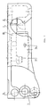
- the frame of the lower-edge hinge depicted in Figure 1, is indicated by reference numeral 1.
- the notch which renders, to the roller in the door, a lateral component of movement is indicated by numeral 2.
- the said roller is indicated by 3.
- the pin 6 of the swiveling part 21 is fitted in a hole 5 in the hinge frame and serves as the pivot axis for the swiveling part.
- the p-shaped groove 7 in the frame is intended for receiving the load-lightening spring 8 of the hinge.
- the frame has a lower surface and an upper surface, between which the notch 2 is formed. In the end receiving the swiveling part there is only the lower surface, the swiveling part forming a surface in the same plane as the upper surface.
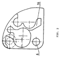
- the swiveling part is attached to the frame by means of the pin 6 and to the door by means of a pin 22.
- the maximum dimensions of the assembled hinge are: approx. 35 mm deep, approx. 105 mm wide, and approx. 17.5 mm high. In the height dimension, the attaching height of the attaching wall occupies approx. 4.5 mm.
- the hinge structure has as its essential parts a separate slide 9 and a spring 10 acting on it, as well as a latch 11 with its spring 11a.
- the slide 9 is fitted in the lower surface of the frame, between one of the vertical walls and a stop 12 and guide 13 opposite that wall, and is capable of reciprocating in its own longitudinal direction, guided by the guides.
- the lower surface of the frame also has a pin 14, which serves as a limiter and mates with an opening 15 in the slide.
- the latch 11 with its spring is located in the swiveling part 21, in the vertical partition wall 16 of which there is a notch corresponding to the latch end and a concave arch corresponding to the spring 11a of the latch.
- the slide 9 has a bore 17, parallel to the direction of movement of the slide, into which bore one end of the spring 10 loading the slide is fitted.
- the length and rigidity of the spring 10 have been adjusted so that the spring will be compressed between the slide bore 17 and the stop 12 abutting the other end of the spring.
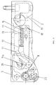
- the free end of the latch 11 has been fitted to extend, in the closed position of the door, somewhat beyond the said stop 12; see Figures 3 and 6a.
- That end 18 of the slide 9 which faces the notch is cam-shaped and in the closed position of the door protrudes so far into the notch area that the roller 3 will touch the oblique surface inside the cam. Simultaneously the roller 3 will touch the opposite wall of the notch 2, which wall forms another cam 19, but in the opposite direction.
- phase 6a to phase 6b the door has opened through only a few degrees, but has at the same time moved laterally approx. 3-4 mm.
- the most important objective of the invention has been achieved, i.e. the opening of the door in a yielding fashion so that the seals of the door will not rub against each other.
- the door has opened slightly more, primarily with respect to the opening angle, and the slide 9 has moved to behind the roller 3 in the notch 2, and the latch 11 is locked against the stop 12. Thereafter the door will pivot about the pin 22 and the swiveling part 21 is propped in a stationary state through the action of the latch 11 bearing on the stop 12.
- the hinge structure will not yield when the door moves. For this reason the hinge is very durable.
- another important objective of the invention has been achieved.
- the door is free to open through up to 270°, and owing to the said latch solution, moving even a heavily loaded door within the opening range 0 - 270° will not strain the hinge detrimentally.
- the slide 9 will be pushed to the left (from the situation of Figure 6c), the rear end 20 of the slide sliding along the shaped arm of the latch 11.
- the roller is at the cam peaks 18 and 19, the slide has detached the latch end from the stop 12 by pushing, whereupon the swiveling part is free to pivot counterclockwise under the effect of the closing movement.
- the closing movement is enhanced and sped up by the slide 9, which projects behind the roller 3 and closes the door in a moment, thereby increasing the closing force.
- the rapid closing is also promoted by the magnet generally used in the seals. The closing, of course, takes place primarily from the side; as does the opening, and so no rubbing of the seals will occur in connection with the closing.
- the spring 8 depicted in Figure 3 is used only in the lower hinge of the door, where the weight of the door loads the hinge. It is intended for lightening thy load, but is not indispensable. It is not used in the upper hinge of the door, as is evident from Figure 5.
- FIG. 5 depicts a limiter plate 23, which is fastened to the swiveling part by means of a screw.
- the cover plate 24, covering the latch, the slide and the spring, is attached to the frame by means of a screw.
Landscapes
- Engineering & Computer Science (AREA)
- Mechanical Engineering (AREA)
- General Engineering & Computer Science (AREA)
- Combustion & Propulsion (AREA)
- Physics & Mathematics (AREA)
- Thermal Sciences (AREA)
- Chemical & Material Sciences (AREA)
- Refrigerator Housings (AREA)
- Hinges (AREA)
- Closing And Opening Devices For Wings, And Checks For Wings (AREA)
- Polysaccharides And Polysaccharide Derivatives (AREA)
- Medicines Containing Plant Substances (AREA)
- Pyridine Compounds (AREA)
- Hinge Accessories (AREA)
Abstract
Description
- The present invention relates to a hinge for French doors in a refrigerator. More precisely, the invention relates to a hinge according to the preamble of
Claim 1. - In a refrigerator, as in a window structure, French doors are opposite doors covering the opening, without a post between them. In connection with a refrigerator this means that the inside vertical edges of the doors must seal effectively against each other. The seals of the doors must not rub against each other during the opening of both of the doors, or only one of the doors. Rubbing would cause wear of the seals and would make the opening of the doors more difficult.
- For this reason, the doors must open with a yielding movement, i.e. with a movement taking place simultaneously both outward and laterally, and not with the conventional movement taking place along the arc of a circle. Thus the seal surfaces will not rub against each other.
- In addition, the hinge should be of small dimensions and in particular such that the hinge will not protrude beyond the side-wall plane. The hinge should be easy to use and reliable in such a manner that the door will open and close easily and, beyond a certain angle of opening, it will remain open by itself and will close rapidly when the opening angle has reached a sufficiently small angle. In addition, the hinge should be durable, allowing the door to be opened completely, i.e. through almost 270°.
- There is available on the market today, a hinge used in French doors of a refrigerator. This hinge is a relatively large-sized structure and therefore aesthetically poor. It extends in the lateral direction of the refrigerator beyond the plane of the side wall and also protrudes from the frontal plane of the refrigerator. The yielding movement, i.e. the lateral component of the movement, is effected with the aid of a notch in the swiveling part of the hinge so that the notch will guide the path of movement of the door, a guide roller in the hinge frame sliding in this notch. The swiveling part turns about a pin which is at the end of an arm attached to a spring.
- In addition to the prior-art hinge being large-sized and protruding beyond the dimensions of the refrigerator, its path of movement is limited. The door opens at maximum through only approx. 110°. Also, the hinge structure is weak, since the weight of the door strains the said spring and for this reason clunks during opening when the doors are loaded. If the spring breaks, the hinge will be unserviceable.
- The object of the present invention is to provide, for French doors in a refrigerator,a hinge from which the above disadvantages have been eliminated.
- This is achieved with the hinge structure according to the invention, the principal characteristics of which are given in the characterizing clause of
claim 1. - The hinge structure according to the invention is small in size and aesthetically pleasing. When installed in place it does not protrude beyond the side plane or the frontal plane of the refrigerator. It is strong and enables the doors to be opened through an angle ranging from 0 to 270° without the hinge bending yielding and thereby straining the structure. The hinge is easy to open and close. The first, primarily lateral, opening phase is rapid. After the first opening phase the hinge is stationary and the door pivots only about the hinge pin. The last, primarily lateral, closing phase occurs rapidly with the additional effect produced by the spring. The opposite door remains closed, if so desired, while one door is being opened.
- The hinge according to the invention is described below in the form of a preferred embodiment, with reference to the accompanying drawings, in which:
- Figure 1 depicts a top plan view of the hinge frame for the lower edge of the door,
- Figure 2 depicts, from the side turning to face the hinge frame, the swiveling part which attaches the door and constitutes part of the hinge frame depicted in Figure 1,
- Figure 3 depicts the hinge parts depicted in Figure 1 and Figure 2, interconnected in the operating position,
- Figure 4 depicts a front view of the combination according to Figure 3,
- Figure 5 depicts the frame and swiveling part of a hinge for the upper edge of the door, interconnected in the operating position,
- Figures 6a, 6b and 6c depict a hinge according to Figure 3, attached to the lower edge of a door, in operation, i.e. a) in the closed position, b) slightly before the extreme position of the phase of lateral movement, and c) with the lateral movement locked, the door opening freely,
- Figure 7 depicts a separate latch part made of thermosetting plastic, and
- Figure 8 depicts a separate slide made of thermosetting plastic.
- In all the figures the corresponding parts are indicated by the same reference numerals. The frame and swiveling part of the hinge are preferably made of a pressure-casting mix and the separate parts, such as the latch, the slide and the roller, of thermosetting plastic.
- The frame of the lower-edge hinge, depicted in Figure 1, is indicated by
reference numeral 1. The notch which renders, to the roller in the door, a lateral component of movement is indicated bynumeral 2. The said roller is indicated by 3. Thepin 6 of theswiveling part 21 is fitted in ahole 5 in the hinge frame and serves as the pivot axis for the swiveling part. The p-shaped groove 7 in the frame is intended for receiving the load-lighteningspring 8 of the hinge. The frame has a lower surface and an upper surface, between which thenotch 2 is formed. In the end receiving the swiveling part there is only the lower surface, the swiveling part forming a surface in the same plane as the upper surface. The swiveling part is attached to the frame by means of thepin 6 and to the door by means of apin 22. The maximum dimensions of the assembled hinge are: approx. 35 mm deep, approx. 105 mm wide, and approx. 17.5 mm high. In the height dimension, the attaching height of the attaching wall occupies approx. 4.5 mm. - The hinge structure has as its essential parts a
separate slide 9 and aspring 10 acting on it, as well as alatch 11 with itsspring 11a. Theslide 9 is fitted in the lower surface of the frame, between one of the vertical walls and astop 12 and guide 13 opposite that wall, and is capable of reciprocating in its own longitudinal direction, guided by the guides. The lower surface of the frame also has apin 14, which serves as a limiter and mates with anopening 15 in the slide. Thelatch 11 with its spring is located in theswiveling part 21, in thevertical partition wall 16 of which there is a notch corresponding to the latch end and a concave arch corresponding to thespring 11a of the latch. Theslide 9 has abore 17, parallel to the direction of movement of the slide, into which bore one end of thespring 10 loading the slide is fitted. The length and rigidity of thespring 10 have been adjusted so that the spring will be compressed between theslide bore 17 and thestop 12 abutting the other end of the spring. The free end of thelatch 11 has been fitted to extend, in the closed position of the door, somewhat beyond the saidstop 12; see Figures 3 and 6a. In the closed position of the door the roller 3 at the lower edge of the door is in thenotch 2. Thatend 18 of theslide 9 which faces the notch is cam-shaped and in the closed position of the door protrudes so far into the notch area that the roller 3 will touch the oblique surface inside the cam. Simultaneously the roller 3 will touch the opposite wall of thenotch 2, which wall forms anothercam 19, but in the opposite direction. - When the door is being opened and the roller 3 retracts from the
notch 2, thecam 19 will force the roller to move in the lateral direction; in Figures 3 and 4 to the left. There-upon the roller 3 for its part will force theslide end 18 to move likewise to the left, thereby compressing thespring 10. Therear slide end 20, which is a cam delimited by a straight line and an arc, will gradually meet the arm of thelatch 11 and detach the latch from its contact with thestop 12 against the spring force of thespring 11a. Simultaneously the swivelingpart 21 will swivel somewhat outward in the lateral direction along with the door movement; see Figures 6a-6c. When the roller 3 is at thepeak 19 of the cam of the frame and simultaneously presses theslide 9 at thepeak 18 of its cam, thefront end 20 of theslide 9 has detached the latch end from thestop 12; Figure 6b. When the door moves still more, the roller 3 will move along the surface subsequent to thecam 19 and will pass theslide peak 18, whereupon theslide 9 is pushed to the right by the action of thespring 10. At the same time the free end of thelatch 11 will move to thestop 12, the slide having been pushed out of the way, i.e. to the right in Figure 6c, under the action of the spring force of thespring 11a. In this position thelatch 11 locks the lateral movement of the hinge, and the door will open freely about thepin 22. From phase 6a to phase 6b the door has opened through only a few degrees, but has at the same time moved laterally approx. 3-4 mm. Thus the most important objective of the invention has been achieved, i.e. the opening of the door in a yielding fashion so that the seals of the door will not rub against each other. By the time of phase 6c, the door has opened slightly more, primarily with respect to the opening angle, and theslide 9 has moved to behind the roller 3 in thenotch 2, and thelatch 11 is locked against thestop 12. Thereafter the door will pivot about thepin 22 and the swivelingpart 21 is propped in a stationary state through the action of thelatch 11 bearing on thestop 12. Thus the hinge structure will not yield when the door moves. For this reason the hinge is very durable. Thus another important objective of the invention has been achieved. - The door is free to open through up to 270°, and owing to the said latch solution, moving even a heavily loaded door within the opening range 0 - 270° will not strain the hinge detrimentally. When the door is being closed after having been opened, the following will occur when the roller 3 arrives in the
notch 2. Theslide 9 will be pushed to the left (from the situation of Figure 6c), therear end 20 of the slide sliding along the shaped arm of thelatch 11. When the roller is at the cam peaks 18 and 19, the slide has detached the latch end from thestop 12 by pushing, whereupon the swiveling part is free to pivot counterclockwise under the effect of the closing movement. The closing movement is enhanced and sped up by theslide 9, which projects behind the roller 3 and closes the door in a moment, thereby increasing the closing force. The rapid closing is also promoted by the magnet generally used in the seals. The closing, of course, takes place primarily from the side; as does the opening, and so no rubbing of the seals will occur in connection with the closing. - The
spring 8 depicted in Figure 3 is used only in the lower hinge of the door, where the weight of the door loads the hinge. It is intended for lightening thy load, but is not indispensable. It is not used in the upper hinge of the door, as is evident from Figure 5. - The lower and upper hinges function in principle in exactly the same manner. However, there are nonessential additional differences between their structures, mainly owing to their different locations. The openings in the upper and lower surfaces of the hinge are covered with cover plates. Figure 5 depicts a limiter plate 23, which is fastened to the swiveling part by means of a screw. The
cover plate 24, covering the latch, the slide and the spring, is attached to the frame by means of a screw. - Fault-less functioning of the hinge requires high precision in the design of not only the notch but also of the latch, the
latch spring 11a and both ends of theslide 9. This can be defined in the main geometrically. Figures 3 and 5 show that the guiding edge of thenotch 2 may be of a different shape at the mouth opening; in one hinge the angle is sharper, in the other more gentle. The figures depicting thenotch 2 also show that its outlines are made up of circular arcs of various sizes. In addition, the resilience of thelatch 11 and the rigidity of thespring 10 affect the functioning. - It is clear that the details of the hinge structure can be varied within the art. What is essential is the forced lateral movement caused by the roller, the bearing of the swiveling part of the hinge against the stop in order to absorb loads, and the enhancing of the closing movement by means of a rapid slide movement. The embodiment depicted above provides an advantageous example of how this can be accomplished.
Claims (6)
- A hinge for French doors in a refrigerator, the hinge comprising a frame (1) which is intended to be attached to the cabinet part of the refrigerator and a swiveling part (21) which is pivotally attached to the hinge frame and serves as the hinge pin of the door, and furthermore a notch (2) and a roller (3) working in conjunction with each other in order to cause a force-guided lateral movement, characterized in that the notch (2) is located in the hinge frame (1) and the roller (3) is for location at the upper or respectively lower edge of the door; and in that the hinge also has a spring-loaded slide (9) which receives its reciprocating movement from the said roller, and a locking member (11) guided by the slide.
- A hinge according to Claim 1, characterized in that at one end of the slide (9) there is a cam (18) which extends into the notch (2), to the area of influence of the roller (3).
- A hinge according to Claim 1 or 2, characterized in that that end (20) of the slide (9) which is farther away from the notch (2) is able to act on the locking member (11) in the pushed-in state of the slide, thereby promoting the closing of the door and increasing the closing force.
- A hinge according to any of the above claims, characterized in that the locking member is made up of a latch (11) fitted pivotally to the swiveling part (21) of the hinge, the latch having a spring (11a) which bears on the swiveling part, and in that the latch can be moved against a fixed stop (12) in order to lock the lateral movement of the hinge while the door rotates freely.
- A hinge according to Claim 4, characterized in that the spring (11a) is a hook-shaped member which is integral with the latch (11).
- A hinge according to any of the above claims, characterized in that there is a load-lightening spring (8) fitted between the swiveling part (21) and the frame (1).
Applications Claiming Priority (3)
| Application Number | Priority Date | Filing Date | Title |
|---|---|---|---|
| FI894185 | 1989-09-05 | ||
| FI894185A FI83561C (en) | 1989-09-05 | 1989-09-05 | Hinges for French doors in refrigerators |
| PCT/FI1990/000208 WO1991003616A1 (en) | 1989-09-05 | 1990-09-04 | A hinge for french doors in a refrigerator |
Publications (2)
| Publication Number | Publication Date |
|---|---|
| EP0490928A1 EP0490928A1 (en) | 1992-06-24 |
| EP0490928B1 true EP0490928B1 (en) | 1994-08-31 |
Family
ID=8528944
Family Applications (1)
| Application Number | Title | Priority Date | Filing Date |
|---|---|---|---|
| EP90913025A Expired - Lifetime EP0490928B1 (en) | 1989-09-05 | 1990-09-04 | A hinge for french doors in a refrigerator |
Country Status (6)
| Country | Link |
|---|---|
| EP (1) | EP0490928B1 (en) |
| JP (1) | JPH05502277A (en) |
| AT (1) | ATE110817T1 (en) |
| DE (1) | DE69012136T2 (en) |
| FI (1) | FI83561C (en) |
| WO (1) | WO1991003616A1 (en) |
Cited By (4)
| Publication number | Priority date | Publication date | Assignee | Title |
|---|---|---|---|---|
| DE20114654U1 (en) * | 2001-09-05 | 2003-02-06 | Liebherr-Hausgeräte GmbH, 88416 Ochsenhausen | Fridge and freezer |
| CN104033058A (en) * | 2014-06-30 | 2014-09-10 | 合肥美菱股份有限公司 | Multifunctional refrigerator lower hinge device |
| CN104514453A (en) * | 2013-09-26 | 2015-04-15 | 泰州乐金电子冷机有限公司 | Hinge device for refrigerators |
| CN111542671A (en) * | 2017-12-29 | 2020-08-14 | 夏普株式会社 | Door opening device, door opening and closing device, and refrigerator |
Families Citing this family (7)
| Publication number | Priority date | Publication date | Assignee | Title |
|---|---|---|---|---|
| CA2231319C (en) * | 1998-03-05 | 2004-07-06 | Les Jeziorowski | Refrigerator door seal assembly |
| CA2239746C (en) * | 1998-06-05 | 2002-03-26 | Camco Inc. | French door gasket corner seal |
| JP2006057904A (en) * | 2004-08-19 | 2006-03-02 | Mitsubishi Electric Corp | refrigerator |
| DE202004016729U1 (en) * | 2004-10-28 | 2006-03-02 | Liebherr-Hausgeräte Lienz Gmbh | door holder |
| CN109594876B (en) * | 2018-12-21 | 2024-01-30 | 江苏玖星精密科技集团有限公司 | Hinge for refrigerator door |
| CN114961473B (en) * | 2021-02-26 | 2023-10-27 | 青岛海尔电冰箱有限公司 | Hinge assembly with stopper and refrigeration equipment with same |
| WO2022227682A1 (en) * | 2021-04-30 | 2022-11-03 | 合肥美的电冰箱有限公司 | Door assembly and refrigeration device |
Family Cites Families (2)
| Publication number | Priority date | Publication date | Assignee | Title |
|---|---|---|---|---|
| DE3218838C2 (en) * | 1982-05-19 | 1986-07-31 | Licentia Patent-Verwaltungs-Gmbh, 6000 Frankfurt | Device for automatic closing of doors with a smaller opening angle, especially refrigerator or freezer doors |
| JPS5948578A (en) * | 1982-09-14 | 1984-03-19 | 株式会社東芝 | Door pivot apparatus of storage housing |
-
1989
- 1989-09-05 FI FI894185A patent/FI83561C/en not_active IP Right Cessation
-
1990
- 1990-09-04 DE DE69012136T patent/DE69012136T2/en not_active Expired - Fee Related
- 1990-09-04 JP JP2511769A patent/JPH05502277A/en active Pending
- 1990-09-04 WO PCT/FI1990/000208 patent/WO1991003616A1/en not_active Ceased
- 1990-09-04 AT AT90913025T patent/ATE110817T1/en not_active IP Right Cessation
- 1990-09-04 EP EP90913025A patent/EP0490928B1/en not_active Expired - Lifetime
Cited By (7)
| Publication number | Priority date | Publication date | Assignee | Title |
|---|---|---|---|---|
| DE20114654U1 (en) * | 2001-09-05 | 2003-02-06 | Liebherr-Hausgeräte GmbH, 88416 Ochsenhausen | Fridge and freezer |
| CN104514453A (en) * | 2013-09-26 | 2015-04-15 | 泰州乐金电子冷机有限公司 | Hinge device for refrigerators |
| CN104514453B (en) * | 2013-09-26 | 2016-08-17 | 泰州乐金电子冷机有限公司 | Hinge means for refrigerator |
| CN104033058A (en) * | 2014-06-30 | 2014-09-10 | 合肥美菱股份有限公司 | Multifunctional refrigerator lower hinge device |
| CN104033058B (en) * | 2014-06-30 | 2016-01-20 | 合肥美菱股份有限公司 | One kind of multiple function refrigerator lower jaw devices |
| CN111542671A (en) * | 2017-12-29 | 2020-08-14 | 夏普株式会社 | Door opening device, door opening and closing device, and refrigerator |
| CN111542671B (en) * | 2017-12-29 | 2021-09-28 | 夏普株式会社 | Door opening device, door opening and closing device, and refrigerator |
Also Published As
| Publication number | Publication date |
|---|---|
| FI894185A0 (en) | 1989-09-05 |
| FI83561B (en) | 1991-04-15 |
| FI83561C (en) | 1991-07-25 |
| DE69012136T2 (en) | 1994-12-22 |
| JPH05502277A (en) | 1993-04-22 |
| EP0490928A1 (en) | 1992-06-24 |
| ATE110817T1 (en) | 1994-09-15 |
| WO1991003616A1 (en) | 1991-03-21 |
| DE69012136D1 (en) | 1994-10-06 |
Similar Documents
| Publication | Publication Date | Title |
|---|---|---|
| CN103061630B (en) | Hinge structure | |
| US2701157A (en) | Latch mechanism | |
| EP0490928A1 (en) | A hinge for french doors in a refrigerator. | |
| US4858272A (en) | Door closing device | |
| JP3286828B2 (en) | refrigerator | |
| CN112780134A (en) | Handle assembly for a door of a vehicle | |
| KR102000902B1 (en) | Hinge hardware | |
| WO2026067011A1 (en) | Multi-joint self-closing hinge and refrigerator | |
| US5269573A (en) | Devices for restricting the movement of doors | |
| CN214740539U (en) | Locking structure of cabinet door leaf | |
| EP2281983B1 (en) | Snap lock assembly | |
| US6065248A (en) | Cremorne lock mounting device for window | |
| JPH0728371Y2 (en) | Heart lock | |
| US3041098A (en) | Latch assembly for surface-mounted doors | |
| CN220415225U (en) | Door and window system | |
| KR100607678B1 (en) | Refrigerator | |
| JP3878526B2 (en) | runner | |
| CN219344321U (en) | Door lock with positionable handle | |
| JP3232438B2 (en) | Lid opening and closing device | |
| JP2002227489A (en) | Sliding-door lock with fitting | |
| US3369832A (en) | Door catch assembly | |
| EP1022419B1 (en) | Compound hinge | |
| JP2551536Y2 (en) | Window Shoji Stay | |
| CN221143959U (en) | Three-dimensional adjustable blind hinge | |
| CN222121336U (en) | Door opening structure |
Legal Events
| Date | Code | Title | Description |
|---|---|---|---|
| PUAI | Public reference made under article 153(3) epc to a published international application that has entered the european phase |
Free format text: ORIGINAL CODE: 0009012 |
|
| 17P | Request for examination filed |
Effective date: 19920228 |
|
| AK | Designated contracting states |
Kind code of ref document: A1 Designated state(s): AT BE CH DE DK FR GB IT LI LU NL SE |
|
| 17Q | First examination report despatched |
Effective date: 19930727 |
|
| GRAA | (expected) grant |
Free format text: ORIGINAL CODE: 0009210 |
|
| AK | Designated contracting states |
Kind code of ref document: B1 Designated state(s): AT BE CH DE DK FR GB IT LI LU NL SE |
|
| PG25 | Lapsed in a contracting state [announced via postgrant information from national office to epo] |
Ref country code: NL Effective date: 19940831 Ref country code: LI Effective date: 19940831 Ref country code: DK Effective date: 19940831 Ref country code: CH Effective date: 19940831 Ref country code: BE Effective date: 19940831 Ref country code: AT Effective date: 19940831 |
|
| REF | Corresponds to: |
Ref document number: 110817 Country of ref document: AT Date of ref document: 19940915 Kind code of ref document: T |
|
| PG25 | Lapsed in a contracting state [announced via postgrant information from national office to epo] |
Ref country code: LU Free format text: LAPSE BECAUSE OF NON-PAYMENT OF DUE FEES Effective date: 19940930 |
|
| REF | Corresponds to: |
Ref document number: 69012136 Country of ref document: DE Date of ref document: 19941006 |
|
| ITF | It: translation for a ep patent filed | ||
| PG25 | Lapsed in a contracting state [announced via postgrant information from national office to epo] |
Ref country code: SE Effective date: 19941130 Ref country code: GB Effective date: 19941130 |
|
| REG | Reference to a national code |
Ref country code: CH Ref legal event code: PL |
|
| ET | Fr: translation filed | ||
| NLV1 | Nl: lapsed or annulled due to failure to fulfill the requirements of art. 29p and 29m of the patents act | ||
| PLBE | No opposition filed within time limit |
Free format text: ORIGINAL CODE: 0009261 |
|
| STAA | Information on the status of an ep patent application or granted ep patent |
Free format text: STATUS: NO OPPOSITION FILED WITHIN TIME LIMIT |
|
| GBPC | Gb: european patent ceased through non-payment of renewal fee |
Effective date: 19941130 |
|
| 26N | No opposition filed | ||
| PGFP | Annual fee paid to national office [announced via postgrant information from national office to epo] |
Ref country code: DE Payment date: 19960919 Year of fee payment: 7 |
|
| PGFP | Annual fee paid to national office [announced via postgrant information from national office to epo] |
Ref country code: FR Payment date: 19960930 Year of fee payment: 7 |
|
| PG25 | Lapsed in a contracting state [announced via postgrant information from national office to epo] |
Ref country code: FR Free format text: THE PATENT HAS BEEN ANNULLED BY A DECISION OF A NATIONAL AUTHORITY Effective date: 19970930 |
|
| PG25 | Lapsed in a contracting state [announced via postgrant information from national office to epo] |
Ref country code: DE Free format text: LAPSE BECAUSE OF NON-PAYMENT OF DUE FEES Effective date: 19980603 |
|
| REG | Reference to a national code |
Ref country code: FR Ref legal event code: ST |
|
| PG25 | Lapsed in a contracting state [announced via postgrant information from national office to epo] |
Ref country code: IT Free format text: LAPSE BECAUSE OF NON-PAYMENT OF DUE FEES;WARNING: LAPSES OF ITALIAN PATENTS WITH EFFECTIVE DATE BEFORE 2007 MAY HAVE OCCURRED AT ANY TIME BEFORE 2007. THE CORRECT EFFECTIVE DATE MAY BE DIFFERENT FROM THE ONE RECORDED. Effective date: 20050904 |