EP0490766B1 - Method for safe packaging of shaped charges for transport - Google Patents
Method for safe packaging of shaped charges for transport Download PDFInfo
- Publication number
- EP0490766B1 EP0490766B1 EP91403365A EP91403365A EP0490766B1 EP 0490766 B1 EP0490766 B1 EP 0490766B1 EP 91403365 A EP91403365 A EP 91403365A EP 91403365 A EP91403365 A EP 91403365A EP 0490766 B1 EP0490766 B1 EP 0490766B1
- Authority
- EP
- European Patent Office
- Prior art keywords
- charges
- shaped
- charge
- jet
- shipping container
- Prior art date
- Legal status (The legal status is an assumption and is not a legal conclusion. Google has not performed a legal analysis and makes no representation as to the accuracy of the status listed.)
- Expired - Lifetime
Links
Images

Classifications
-
- F—MECHANICAL ENGINEERING; LIGHTING; HEATING; WEAPONS; BLASTING
- F42—AMMUNITION; BLASTING
- F42B—EXPLOSIVE CHARGES, e.g. FOR BLASTING, FIREWORKS, AMMUNITION
- F42B39/00—Packaging or storage of ammunition or explosive charges; Safety features thereof; Cartridge belts or bags
- F42B39/14—Explosion or fire protection arrangements on packages or ammunition
Definitions
- the subject matter of the present invention relates to a new method for safely packaging shaped charges for transportation by common carrier and to a container with shaped charges.
- a box of commercial oil-well shaped charges must be transported by common airline carrier, the box of shaped charges must be certified "class C" by a competent authority, such as the Department of Transportion.
- a competent authority such as the Department of Transportion.
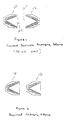
- the jet produced therefrom must not propagate outside of the shipping box. This is normally accomplished by packaging the charges in a pairwise fashion, as shown in figure 1, so that the jet from the detonated shaped charge is destroyed by the induced detonation and subsequent liner collapse of the opposing shaped charge.
- the shaped charges be arranged as in figure 1 and not as in figure 2, since otherwise the first shaped charge would merely detonate the second shaped charge and cause propagation of a second jet.
- the problem with the arrangement shown in figure 1, however, is that some shaped charge designs produce jets which are sufficiently long, fast, and coherent enough to penetrate the adjacent mirror-imaged shaped charge, thus potentially exiting the shipping box; that is, the jet may be powerful enough so that some of it will pass through the destructive influence of the explosive detonation and through the collapse of the adjacent shaped charge. If this happens, the jet may endanger structures or persons present within the immediate vicinity of the shipping box. A severe safety hazard is created.
- a method of packaging shaped explosive charges in a shipping container said shaped explosive charges each having a pointing direction defined as the direction in which the jet created during the detonation of the shaped charge is directed, said method comprising the steps of: disposing a first plurality of shaped explosive charges adjacent to and axially in line with each other in said shipping container, said first plurality of shaped charges being positioned in said shipping container so that each of said first shaped charges has the same pointing direction; and disposing a second plurality of shaped explosive charges adjacent to and axially in line with each other and with said first plurality of charges in said shipping container, said second plurality of shaped charges being positioned in said shipping container so that each of said second charges has the same pointing direction, which is aligned with and opposite to the pointing direction of the first plurality of shaped charges so as to oppose the jet from any of said first plurality of charges.
- a container of shaped explosive charges each shaped charge having a pointing direction defined as the direction in which the jet created during the detonation of the shaped charge is directed, said container comprising: a shipping container; a first plurality of shaped explosive charges disposed adjacent to and axially in line with each other in said shipping container, said first plurality of shaped charges being positioned in said shipping container so that each of said first shaped charges has the same pointing direction; and a second plurality of shaped explosive charges disposed adjacent to and axially in line with each other and with said first plurality of charges in said shipping container, said second plurality of shaped charges being positioned in said shipping container so that each of said second charges has the same pointing direction, which is aligned with and opposite to the pointing direction of the first plurality of shaped charges so as to oppose the jet from any of said first plurality of charges.
- FIG 1 a prior art method for packaging shaped charges in a shipping box for transport is illustrated.
- shaped charges which are adapted for use in a perforating gun, to be carefully packaged in shipping boxes prior to transport by common carrier from one location to another.
- This packaging is required in order to prevent an accidental detonation of a shaped charge in the box from endangering persons or structures in the immediate vicinity of the shipping box. For example, if a shaped charge detonates, the jet produced from the charge may exit the box and detonate or ignite other surrounding structures present within the carrier. Therefore, government authorities require that the shaped charges be packaged within the shipping box in a specific manner which will prevent the jet, produced from an accidentally detonated shaped charge, from exiting the box.
- Figure 1 is a prior art packaging method wherein a first shaped charge 10 has an open end 10-1 which faces an open end 12-1 of a second shaped charge 12. In operation, if the first shaped charge 10 detonates, the second shaped charge 12 will theoretically absorb the jet produced from the first shaped charge 10.
- Figure 2 is an example of how not to package shaped charges within a shipping box during transport.
- charges 14 and 16 point in the same direction. If both charges point in the same direction, an accidential detonation of one charge 14 will initiate detonation of the adjacent charge 16 with its subsequent jet exiting the shipping box.
- the first and second charges 10 and 12 must face each other, so that one charge will tend to absorb the jet produced from the other charge.
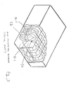
- Figure 3 illustrates a shipping box in which the Applicant has implemented the prior art packaging method of figure 1.
- the first shaped charge 10 has its open end 10-1 facing the open end 12-1 of the second shaped charge 12, as shown in figure 1; the first and second shaped charges 10 and 12 are arranged in a plurality of columns within the box.
- Another packaging method is needed, when packing shaped charges within a shipping box, to prevent a jet, produced from an accidentally detonated shaped charge in the shipping box, from exiting the box and detonating shaped charges disposed in other boxes and/or endangering surrounding persons or structures.
- FIG 4 a packaging method in accordance with the present invention is illustrated for packaging shaped charges in a shipping box.
- the first shaped charge 10 and the second shaped charge 12 face each other, as in figure 1; however, a third shaped charge 18 is disposed behind the first shaped charge 10, and a fourth shaped charge 20 is disposed behind the second shaped charge 12, the open end of the fourth shaped charge 20 facing the closed end of the second shaped charge 12 and facing the open end of the first and third shaped charges 10 and 18, respectively.
- figure 4 illustrates four charges 10, 12, 18 and 20, as shown in figure 5, more than four charges may exist for accomplishing the main purpose of this invention; that is, a fifth shaped charge may be disposed behind the third shaped charge 18 and a sixth shaped charge may be disposed behind the second shaped charge 12. This concept is illustrated in figure 5.
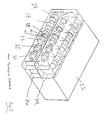
- FIG 5 a three-dimensional view of a shipping box utilizing the packaging method of figure 4 in accordance with the present invention is illustrated, the shaped charges being arranged in rows and packaged in accordance with the new packaging method of figure 4.
- the first, second, third and fourth shaped charges 10, 12, 18 and 20, respectively, of figure 4 are arranged in rows (not columns) within a shipping box 22.
- a top part 24 of the box 22 includes a plurality of rows and a bottom part 26 of the box 22 includes a plurality of rows, each row in the box 22 including three shaped charges facing in one direction and three shaped charges facing in a direction opposite to the one direction.
- a fifth shaped charge 28 is disposed behind the third shaped charge 18 and faces in the one direction
- a sixth shaped charge 30 is disposed behind the fourth shaped charge 20 and faces in the direction opposite to the one direction.
- the open end 10-1 of the first shaped charge 10 faces or points in the one direction
- the open end 12-1 of the second shaped charge 12 faces or points in the direction opposite to the one direction.
- the jet produced from the charge 10 must pass through three other shaped charges, the second, fourth, and sixth shaped charges 12, 20, and 30, respectively.
- the jet from the charge 10 may conceivably pass through the second charge 12, it cannot also pass through the fourth and sixth shaped charges 20 and 30, respectively and exit the shipping box 22. Therefore, since the jet from the first shaped charge 10 cannot pass through the sixth shaped charge 30 and exit the shipping box 22, if the third and/or fifth shaped charges 18 and 28 accidentally detonate, the jets from these charges also cannot pass through the sixth shaped charge 30 and exit the shipping box 22.
Landscapes
- Engineering & Computer Science (AREA)
- General Engineering & Computer Science (AREA)
- Cartons (AREA)
Description
- The subject matter of the present invention relates to a new method for safely packaging shaped charges for transportation by common carrier and to a container with shaped charges.
- If a box of commercial oil-well shaped charges must be transported by common airline carrier, the box of shaped charges must be certified "class C" by a competent authority, such as the Department of Transportion. In accordance with one of the certification requirements, if a shaped charge in a shipping box should accidentally detonate, the jet produced therefrom must not propagate outside of the shipping box. This is normally accomplished by packaging the charges in a pairwise fashion, as shown in figure 1, so that the jet from the detonated shaped charge is destroyed by the induced detonation and subsequent liner collapse of the opposing shaped charge. It is important that the shaped charges be arranged as in figure 1 and not as in figure 2, since otherwise the first shaped charge would merely detonate the second shaped charge and cause propagation of a second jet. The problem with the arrangement shown in figure 1, however, is that some shaped charge designs produce jets which are sufficiently long, fast, and coherent enough to penetrate the adjacent mirror-imaged shaped charge, thus potentially exiting the shipping box; that is, the jet may be powerful enough so that some of it will pass through the destructive influence of the explosive detonation and through the collapse of the adjacent shaped charge. If this happens, the jet may endanger structures or persons present within the immediate vicinity of the shipping box. A severe safety hazard is created.
- Accordingly, it is a primary object of the present invention to provide a safe packaging method for packaging shaped charges in a shipping box during transportation of the box aboard a common carrier, which method will prevent jets developed from even the most powerful shaped charges in the box from exiting the shipping box during transport.
- According to a first aspect of the invention, there is provided a method of packaging shaped explosive charges in a shipping container, said shaped explosive charges each having a pointing direction defined as the direction in which the jet created during the detonation of the shaped charge is directed, said method comprising the steps of:
disposing a first plurality of shaped explosive charges adjacent to and axially in line with each other in said shipping container, said first plurality of shaped charges being positioned in said shipping container so that each of said first shaped charges has the same pointing direction; and
disposing a second plurality of shaped explosive charges adjacent to and axially in line with each other and with said first plurality of charges in said shipping container, said second plurality of shaped charges being positioned in said shipping container so that each of said second charges has the same pointing direction, which is aligned with and opposite to the pointing direction of the first plurality of shaped charges so as to oppose the jet from any of said first plurality of charges. - According to another aspect of the invention, there is provided a container of shaped explosive charges, each shaped charge having a pointing direction defined as the direction in which the jet created during the detonation of the shaped charge is directed, said container comprising:
a shipping container;
a first plurality of shaped explosive charges disposed adjacent to and axially in line with each other in said shipping container, said first plurality of shaped charges being positioned in said shipping container so that each of said first shaped charges has the same pointing direction; and
a second plurality of shaped explosive charges disposed adjacent to and axially in line with each other and with said first plurality of charges in said shipping container, said second plurality of shaped charges being positioned in said shipping container so that each of said second charges has the same pointing direction, which is aligned with and opposite to the pointing direction of the first plurality of shaped charges so as to oppose the jet from any of said first plurality of charges. - Further scope of applicability of the present invention will become apparent from the detailed description presented hereinafter. It should be understood, however, that the detailed description and the specific examples, while representing a preferred embodiment of the present invention, are given by way of illustration only, since various changes and modifications within the spirit and scope of the invention will become obvious to one skilled in the art from a reading of the following detailed description.
- A full understanding of the present invention will be obtained from the detailed description of the preferred embodiment presented hereinbelow, and the accompanying drawings, which are given by way of illustration only and are not intended to be limitative of the present invention, and wherein:
- figure 1 illustrates a prior art packaging method for packaging shaped charges in a shipping box;
- figure 2 illustrates an incorrect packaging method;
- figure 3 illustrates a three-dimensional view of a shipping box utilizing the prior art packaging method of figure 1, the shaped charges being arranged in columns and packaged in accordance with the prior art packaging method;
- figure 4 illustrates a packaging method in accordance with the present invention for packaging shaped charges in a shipping box; and
- figure 5 illustrates a three-dimensional view of a shipping box utilizing the packaging method of figure 4 in accordance with the present invention, the shaped charges being arranged in rows and packaged in accordance with the new packaging method.
- Referring to figure 1, a prior art method for packaging shaped charges in a shipping box for transport is illustrated.
- Government authorities require shaped charges, which are adapted for use in a perforating gun, to be carefully packaged in shipping boxes prior to transport by common carrier from one location to another. This packaging is required in order to prevent an accidental detonation of a shaped charge in the box from endangering persons or structures in the immediate vicinity of the shipping box. For example, if a shaped charge detonates, the jet produced from the charge may exit the box and detonate or ignite other surrounding structures present within the carrier. Therefore, government authorities require that the shaped charges be packaged within the shipping box in a specific manner which will prevent the jet, produced from an accidentally detonated shaped charge, from exiting the box. Figure 1 is a prior art packaging method wherein a first shaped
charge 10 has an open end 10-1 which faces an open end 12-1 of a second shapedcharge 12. In operation, if the firstshaped charge 10 detonates, the secondshaped charge 12 will theoretically absorb the jet produced from the firstshaped charge 10. - Figure 2 is an example of how not to package shaped charges within a shipping box during transport. In figure 2, charges 14 and 16 point in the same direction. If both charges point in the same direction, an accidential detonation of one
charge 14 will initiate detonation of theadjacent charge 16 with its subsequent jet exiting the shipping box. As shown in figure 1, the first andsecond charges - Figure 3 illustrates a shipping box in which the Applicant has implemented the prior art packaging method of figure 1. The first
shaped charge 10 has its open end 10-1 facing the open end 12-1 of the secondshaped charge 12, as shown in figure 1; the first and second shapedcharges - However, there is a problem associated with the packaging arrangement of figures 1 and 3; that is, some shaped charge designs produce jets which are long, fast and coherent enough to pass through the destructive influence of the explosive detonation and through the adjacent shaped charge. When this happens, the jet may exit the shipping box and endanger surrounding persons or structures. Therefore, the prior art packaging method of figures 1 and 3 is insufficient to prevent an accident during transport of the shipping box aboard a carrier.
- Another packaging method is needed, when packing shaped charges within a shipping box, to prevent a jet, produced from an accidentally detonated shaped charge in the shipping box, from exiting the box and detonating shaped charges disposed in other boxes and/or endangering surrounding persons or structures.
- Referring to figure 4, a packaging method in accordance with the present invention is illustrated for packaging shaped charges in a shipping box.
- In figure 4, the first shaped
charge 10 and the second shapedcharge 12 face each other, as in figure 1; however, a third shapedcharge 18 is disposed behind the first shapedcharge 10, and a fourth shapedcharge 20 is disposed behind the second shapedcharge 12, the open end of the fourthshaped charge 20 facing the closed end of the secondshaped charge 12 and facing the open end of the first and third shapedcharges charges charge 18 and a sixth shaped charge may be disposed behind the second shapedcharge 12. This concept is illustrated in figure 5. - Referring to figure 5, a three-dimensional view of a shipping box utilizing the packaging method of figure 4 in accordance with the present invention is illustrated, the shaped charges being arranged in rows and packaged in accordance with the new packaging method of figure 4.
- In figure 5, the first, second, third and fourth shaped
charges top part 24 of the box 22 includes a plurality of rows and a bottom part 26 of the box 22 includes a plurality of rows, each row in the box 22 including three shaped charges facing in one direction and three shaped charges facing in a direction opposite to the one direction. As shown in figure 4, the first and third shapedcharges charges charge 28 is disposed behind the third shapedcharge 18 and faces in the one direction, and a sixth shapedcharge 30 is disposed behind the fourth shapedcharge 20 and faces in the direction opposite to the one direction. The open end 10-1 of the first shapedcharge 10 faces or points in the one direction, and the open end 12-1 of the second shapedcharge 12 faces or points in the direction opposite to the one direction. - In operation, referring to figure 5, if the first
shaped charge 10 accidentally detonates, the jet produced from thecharge 10 must pass through three other shaped charges, the second, fourth, and sixth shapedcharges charge 10 may conceivably pass through thesecond charge 12, it cannot also pass through the fourth and sixth shapedcharges shaped charge 10 cannot pass through the sixth shapedcharge 30 and exit the shipping box 22, if the third and/or fifth shapedcharges shaped charge 30 and exit the shipping box 22. The same may be said with respect to the jets fromshaped charges charge 12 accidentally detonates, the jet produced therefrom may conceivably pass throughcharge 10, but it will not also pass throughcharge 18, let alone through bothcharges charge 12, but, as noted above, the jet fromcharge 12 cannot pass through bothcharges charges
Claims (2)
- A method of packaging shaped explosive charges in a shipping container, said shaped explosive charges each having a pointing direction defined as the direction in which the jet created during the detonation of the shaped charge is directed, said method comprising the steps of:
disposing a first plurality of shaped explosive charges (10,18,28) adjacent to and axially in line with each other in said shipping container (22), said first plurality of shaped charges (10,18,28) being positioned in said shipping container so that each of said first shaped charges has the same pointing direction; and
disposing a second plurality of shaped explosive charges (12,20,30) adjacent to and axially in line with each other and with said first plurality of charges (10,18,28) in said shipping container (22), said second plurality of shaped charges (12,20,30) being positioned in said shipping container so that each of said second charges has the same pointing direction, which is aligned with and opposite to the pointing direction of the first plurality of shaped charges (10,18,28) so as to oppose the jet from any of said first plurality of charges. - A container of shaped explosive charges, each shaped charge having a pointing direction defined as the direction in which the jet created during the detonation of the shaped charge is directed, said container comprising:
a shipping container (22);
a first plurality of shaped explosive charges (10,18,28) disposed adjacent to and axially in line with each other in said shipping container (22), said first plurality of shaped charges (10,18,28) being positioned in said shipping container so that each of said first shaped charges has the same pointing direction; and
a second plurality of shaped explosive charges (12,20,30) disposed adjacent to and axially in line with each other and with said first plurality of charges (10,18,28) in said shipping container (22), said second plurality of shaped charges (12,20,30) being positioned in said shipping container so that each of said second charges has the same pointing direction, which is aligned with and opposite to the pointing direction of the first plurality of shaped charges (10,18,28) so as to oppose the jet from any of said first plurality of charges.
Applications Claiming Priority (2)
| Application Number | Priority Date | Filing Date | Title |
|---|---|---|---|
| US07/626,346 US5097945A (en) | 1990-12-12 | 1990-12-12 | Method for safe packaging of shaped charges for transport |
| US626346 | 1990-12-12 |
Publications (3)
| Publication Number | Publication Date |
|---|---|
| EP0490766A2 EP0490766A2 (en) | 1992-06-17 |
| EP0490766A3 EP0490766A3 (en) | 1992-12-16 |
| EP0490766B1 true EP0490766B1 (en) | 1995-01-18 |
Family
ID=24510012
Family Applications (1)
| Application Number | Title | Priority Date | Filing Date |
|---|---|---|---|
| EP91403365A Expired - Lifetime EP0490766B1 (en) | 1990-12-12 | 1991-12-12 | Method for safe packaging of shaped charges for transport |
Country Status (2)
| Country | Link |
|---|---|
| US (1) | US5097945A (en) |
| EP (1) | EP0490766B1 (en) |
Families Citing this family (9)
| Publication number | Priority date | Publication date | Assignee | Title |
|---|---|---|---|---|
| RU2175108C2 (en) * | 1999-07-19 | 2001-10-20 | Российский федеральный ядерный центр - Всероссийский научно-исследовательский институт технической физики им. акад. Е.И. Забабахина | Method for safe package of cumulative charges for transportation |
| SE520378C2 (en) * | 1999-11-05 | 2003-07-01 | Bofors Carl Gustaf Ab | Methods and apparatus for an over-ignition of an RSV charge by fire or other means resulting in a spread to other nearby charges |
| RU2169343C1 (en) * | 2000-10-03 | 2001-06-20 | Производственное объединение "Алексинский химкомбинат" | Transporting module of sharges to artillery guns |
| US6454085B1 (en) * | 2001-01-18 | 2002-09-24 | Halliburton Energy Services, Inc. | Method and system for packaging explosive products of transportation |
| US7416076B2 (en) * | 2004-01-12 | 2008-08-26 | Halliburton Energy Services, Inc. | Apparatus and method for packaging and shipping of high explosive content components |
| FR2872272B1 (en) * | 2004-06-25 | 2006-08-04 | Giat Ind Sa | CONTAINER FOR AMMUNITION |
| US8006622B2 (en) * | 2006-11-07 | 2011-08-30 | Orica Explosives Technology Pty Ltd | Protector for detonator, and method of use |
| CA3006230C (en) | 2015-12-07 | 2020-06-30 | DynaEnergetics Europe GmbH | Shaped charge metal foam package |
| US12221275B2 (en) | 2021-10-29 | 2025-02-11 | DynaEnergetics Europe GmbH | Mobile perforating bank unit and modular storage container |
Family Cites Families (7)
| Publication number | Priority date | Publication date | Assignee | Title |
|---|---|---|---|---|
| US2142227A (en) * | 1937-03-31 | 1939-01-03 | Robert B Whiteside | Firecracker package |
| GB503358A (en) * | 1938-01-26 | 1939-04-05 | Eric Donald Mackintosh | Improvements in and relating to the wrapping of chocolates and the like |
| US2660300A (en) * | 1950-06-17 | 1953-11-24 | Olin Ind Inc | Packaging explosives |
| US2877891A (en) * | 1958-01-14 | 1959-03-17 | Clovis C Chartrand | Protective packaging for rim fire ammunition and the like |
| US2990945A (en) * | 1958-03-07 | 1961-07-04 | Keyes Fibre Co | Cartridge packing means |
| US3424298A (en) * | 1967-03-22 | 1969-01-28 | Price Wilson Ltd Price Wilson | Ammunition holder |
| DE3805478A1 (en) * | 1988-02-22 | 1989-08-31 | Deutsche Verpackungsmittel | Packing device for an explosive body |
-
1990
- 1990-12-12 US US07/626,346 patent/US5097945A/en not_active Expired - Fee Related
-
1991
- 1991-12-12 EP EP91403365A patent/EP0490766B1/en not_active Expired - Lifetime
Also Published As
| Publication number | Publication date |
|---|---|
| EP0490766A3 (en) | 1992-12-16 |
| US5097945A (en) | 1992-03-24 |
| EP0490766A2 (en) | 1992-06-17 |
Similar Documents
| Publication | Publication Date | Title |
|---|---|---|
| US4440296A (en) | Anti-propagation explosive packaging | |
| US5390580A (en) | Lightweight explosive and fire resistant container | |
| US5097945A (en) | Method for safe packaging of shaped charges for transport | |
| US6454085B1 (en) | Method and system for packaging explosive products of transportation | |
| US4326468A (en) | Blast suppressive shielding | |
| US4458482A (en) | Rocket motor | |
| US7416076B2 (en) | Apparatus and method for packaging and shipping of high explosive content components | |
| US4357873A (en) | Apparatus for destroying structures such as concrete walls | |
| US20210123711A1 (en) | Shaped charge metal foam package | |
| US4347796A (en) | Blast suppressive shielding | |
| US5873455A (en) | Nonpropagation casing | |
| Gozani | Principles of nuclear-based explosive detection systems | |
| USH162H (en) | System and method for wide-area mine clearance | |
| RU2689000C2 (en) | Device for destroyed by blasting of hazardous items and method of producing such device | |
| Harvey et al. | Nuclear weapons safety: The case of trident | |
| Rajaraman et al. | Possession and deployment of nuclear weapons in South Asia: An assessment of some risks | |
| US3899977A (en) | Demolition charges | |
| RU2294866C1 (en) | Method of protection of spacecraft | |
| Đinđića | SEESAC Emergency Protocol (EP1) | |
| Kido | The Doctrine of Military Objective | |
| KR960004336Y1 (en) | Primer containers to prevent chain explosion | |
| RU2175108C2 (en) | Method for safe package of cumulative charges for transportation | |
| Groh | Process Determination and Plant Layout for Western Demilitarization Facility Hawthorne, Nevada | |
| McCollum | Tort Aspects of Space Technology | |
| SCHOCK | Design evolution and verification of the general-purpose heat source(for spacecraft power systems) |
Legal Events
| Date | Code | Title | Description |
|---|---|---|---|
| PUAI | Public reference made under article 153(3) epc to a published international application that has entered the european phase |
Free format text: ORIGINAL CODE: 0009012 |
|
| AK | Designated contracting states |
Kind code of ref document: A2 Designated state(s): FR GB NL |
|
| PUAL | Search report despatched |
Free format text: ORIGINAL CODE: 0009013 |
|
| AK | Designated contracting states |
Kind code of ref document: A3 Designated state(s): FR GB NL |
|
| 17P | Request for examination filed |
Effective date: 19930614 |
|
| 17Q | First examination report despatched |
Effective date: 19930910 |
|
| GRAA | (expected) grant |
Free format text: ORIGINAL CODE: 0009210 |
|
| AK | Designated contracting states |
Kind code of ref document: B1 Designated state(s): FR GB NL |
|
| PG25 | Lapsed in a contracting state [announced via postgrant information from national office to epo] |
Ref country code: NL Effective date: 19950118 |
|
| ET | Fr: translation filed | ||
| NLV1 | Nl: lapsed or annulled due to failure to fulfill the requirements of art. 29p and 29m of the patents act | ||
| PLBE | No opposition filed within time limit |
Free format text: ORIGINAL CODE: 0009261 |
|
| STAA | Information on the status of an ep patent application or granted ep patent |
Free format text: STATUS: NO OPPOSITION FILED WITHIN TIME LIMIT |
|
| 26N | No opposition filed | ||
| PGFP | Annual fee paid to national office [announced via postgrant information from national office to epo] |
Ref country code: GB Payment date: 20001003 Year of fee payment: 10 |
|
| PG25 | Lapsed in a contracting state [announced via postgrant information from national office to epo] |
Ref country code: GB Free format text: LAPSE BECAUSE OF NON-PAYMENT OF DUE FEES Effective date: 20011212 |
|
| PGFP | Annual fee paid to national office [announced via postgrant information from national office to epo] |
Ref country code: FR Payment date: 20011221 Year of fee payment: 11 |
|
| REG | Reference to a national code |
Ref country code: GB Ref legal event code: IF02 |
|
| GBPC | Gb: european patent ceased through non-payment of renewal fee |
Effective date: 20011212 |
|
| PG25 | Lapsed in a contracting state [announced via postgrant information from national office to epo] |
Ref country code: FR Free format text: LAPSE BECAUSE OF NON-PAYMENT OF DUE FEES Effective date: 20030901 |
|
| REG | Reference to a national code |
Ref country code: FR Ref legal event code: ST |