EP0490421B1 - Downhole measurements using very short fractures - Google Patents
Downhole measurements using very short fractures Download PDFInfo
- Publication number
- EP0490421B1 EP0490421B1 EP91203098A EP91203098A EP0490421B1 EP 0490421 B1 EP0490421 B1 EP 0490421B1 EP 91203098 A EP91203098 A EP 91203098A EP 91203098 A EP91203098 A EP 91203098A EP 0490421 B1 EP0490421 B1 EP 0490421B1
- Authority
- EP
- European Patent Office
- Prior art keywords
- fracture
- pumping
- pressure
- fluid
- pump
- Prior art date
- Legal status (The legal status is an assumption and is not a legal conclusion. Google has not performed a legal analysis and makes no representation as to the accuracy of the status listed.)
- Expired - Lifetime
Links
- 238000005259 measurement Methods 0.000 title claims description 10
- 239000012530 fluid Substances 0.000 claims description 28
- 238000000034 method Methods 0.000 claims description 22
- 238000012360 testing method Methods 0.000 claims description 22
- 238000005086 pumping Methods 0.000 claims description 13
- 230000015572 biosynthetic process Effects 0.000 claims description 8
- 239000011435 rock Substances 0.000 claims description 8
- 230000007423 decrease Effects 0.000 claims description 5
- 230000000977 initiatory effect Effects 0.000 claims description 4
- 238000012544 monitoring process Methods 0.000 claims description 3
- 230000000644 propagated effect Effects 0.000 claims 1
- 230000015556 catabolic process Effects 0.000 description 7
- 238000005755 formation reaction Methods 0.000 description 7
- 238000002347 injection Methods 0.000 description 7
- 239000007924 injection Substances 0.000 description 7
- 230000000694 effects Effects 0.000 description 5
- 230000035699 permeability Effects 0.000 description 4
- 238000004458 analytical method Methods 0.000 description 2
- 238000006073 displacement reaction Methods 0.000 description 2
- 238000005553 drilling Methods 0.000 description 2
- 238000003860 storage Methods 0.000 description 2
- XLYOFNOQVPJJNP-UHFFFAOYSA-N water Substances O XLYOFNOQVPJJNP-UHFFFAOYSA-N 0.000 description 2
- 238000013459 approach Methods 0.000 description 1
- 238000009530 blood pressure measurement Methods 0.000 description 1
- 238000012625 in-situ measurement Methods 0.000 description 1
- 238000004519 manufacturing process Methods 0.000 description 1
- 238000012986 modification Methods 0.000 description 1
- 230000004048 modification Effects 0.000 description 1
- 239000011148 porous material Substances 0.000 description 1
Images

Classifications
-
- E—FIXED CONSTRUCTIONS
- E21—EARTH DRILLING; MINING
- E21B—EARTH DRILLING, e.g. DEEP DRILLING; OBTAINING OIL, GAS, WATER, SOLUBLE OR MELTABLE MATERIALS OR A SLURRY OF MINERALS FROM WELLS
- E21B43/00—Methods or apparatus for obtaining oil, gas, water, soluble or meltable materials or a slurry of minerals from wells
- E21B43/25—Methods for stimulating production
- E21B43/26—Methods for stimulating production by forming crevices or fractures
-
- E—FIXED CONSTRUCTIONS
- E21—EARTH DRILLING; MINING
- E21B—EARTH DRILLING, e.g. DEEP DRILLING; OBTAINING OIL, GAS, WATER, SOLUBLE OR MELTABLE MATERIALS OR A SLURRY OF MINERALS FROM WELLS
- E21B49/00—Testing the nature of borehole walls; Formation testing; Methods or apparatus for obtaining samples of soil or well fluids, specially adapted to earth drilling or wells
- E21B49/006—Measuring wall stresses in the borehole
-
- E—FIXED CONSTRUCTIONS
- E21—EARTH DRILLING; MINING
- E21B—EARTH DRILLING, e.g. DEEP DRILLING; OBTAINING OIL, GAS, WATER, SOLUBLE OR MELTABLE MATERIALS OR A SLURRY OF MINERALS FROM WELLS
- E21B49/00—Testing the nature of borehole walls; Formation testing; Methods or apparatus for obtaining samples of soil or well fluids, specially adapted to earth drilling or wells
- E21B49/008—Testing the nature of borehole walls; Formation testing; Methods or apparatus for obtaining samples of soil or well fluids, specially adapted to earth drilling or wells by injection test; by analysing pressure variations in an injection or production test, e.g. for estimating the skin factor
-
- E—FIXED CONSTRUCTIONS
- E21—EARTH DRILLING; MINING
- E21B—EARTH DRILLING, e.g. DEEP DRILLING; OBTAINING OIL, GAS, WATER, SOLUBLE OR MELTABLE MATERIALS OR A SLURRY OF MINERALS FROM WELLS
- E21B49/00—Testing the nature of borehole walls; Formation testing; Methods or apparatus for obtaining samples of soil or well fluids, specially adapted to earth drilling or wells
- E21B49/08—Obtaining fluid samples or testing fluids, in boreholes or wells
- E21B49/10—Obtaining fluid samples or testing fluids, in boreholes or wells using side-wall fluid samplers or testers
Definitions
- the present invention relates to a method of performing rock fracture measurements which is particularly useful for making in-situ measurements of stress, fracture toughness and fracture size in a borehole.
- ⁇ HF micro-hydraulic fracture
- BHP borehole pressure
- T time
- Variations on the ⁇ HF technique described above include step-rate tests and flow back tests. In the latter, the well is shut-in as before and fluid is allowed to flow back from the interval, typically at 10% of the pump-in rate. Monitoring the pressure during flow back can be used to estimate the pressure at which the fracture closes and hence the minimum stress.
- the fluid used is usually a low viscosity fluid such as mud or water and typically not more than 400 l are injected into the formation at flow rates of 0.05-1.0 l/s. Several injection/fall off cycles are performed until repeatable results are obtained. This can take up to three hours. However, despite the long time taken, the estimation of minimum stress may include error of the order of several MPa, especially when the formation is permeable such that pressure leaks from the fracture face.
- a method of performing rock fracture measurements in a borehole comprising isolating a portion of the borehole and alternately pumping a fluid into and removing fluid from said portion so as to increase and decrease the pressure therein respectively while continuously monitoring the fluid pressure in the portion, characterised in that the fluid is pumped into the portion until the initiation of a fracture is indicated, immediately after which fluid is pumped out of the portion so as to prevent propagation of the fracture and allow closure thereof, the portion then being repressurised by pumping fluid back in.
- the pumping in and out can be repeated to obtain several measurements.
- the pump out rate is preferably the same as the pump in rate and is typically 1-100 x 10 ⁇ 4 litre/sec ⁇ 1 for low permeability formations.
- the fracture should be kept as short as possible, typically no greater than about 1 m in length.
- Pumping in and out is preferably achieved using a constant displacement pump.
- the pump can be a downhole pump, immediately adjacent the test interval.
- FIG. 2 shows a typical ⁇ HF tool comprising a tubing line 10 connected to a pump (not shown) for a fracturing fluid such as mud or water.
- Packer modules 12, 14 are mounted on the tube line 10 for isolating an interval 16 of the borehole 18.
- the portion of the line 10 between the packers 12, 14 is provided with injection ports 22 to allow fluid to be pumped into or out of the test interval 16.
- the pump and a pressure sensor are preferably mounted on the line 10 immediately adjacent the tool to reduce response time and minimise any tube line storage effect and increase accuracy as less fluid must be injected or removed to effect a noticeable increase or decrease in pressure.
- the test interval 16 has a typical length of 2 feet (60 cm) and each packer 12, 14 is typically 5 feet (150 cm) long, giving a total length of 12 feet (360 cm). To obtain the required results, the fracture 20 must remain effectively within this limit. Consequently, a fracture length of the order of 1 m is desired.
- the test interval is pressurised as with conventional ⁇ HF by pumping fluid into the test interval using a constant displacement pump.
- the pump in rate is much lower than usual, typically 10 ⁇ 4 litre/sec - 100x10 ⁇ 4 litre/sec.
- the pressure in the test interval is closely monitored and increases until a fracture is initiated (B) at which time the pressure breakdown is observed.
- B fracture is initiated
- the pumping direction is reversed so that fluid is withdrawn from the test interval at substantially the same rate as it was pumped in. This is intended to restrict propagation of the fracture to a minimum and at the pumping rates given above, in low permeability formations, the fracture would be expected to propagate at around 1 m/min.
- the pumping out (PO) should commence within 10-30 seconds of breakdown.
- the pressure is monitored during the pump-out phase and the pressure at which the fracture closes (C) can be determined form the discontinuity in the pressure decrease which can be seen.
- the closure stress (C) is a measure of the minimum stress for the formation ⁇ 3 and the pump back is continued well beyond this to ensure that the fracture is closed and substantially free of fluid.
- test interval is repressurised as shown in Figure 4.
- the repressurisation is essentially the same as the initial pressurisation but analysis of the pressure changes shows further information about the formation and the fracture.
- fluid is pumped out once breakdown is observed indicating re-initiation of the fracture.
- a pressure increase is seen as the interval is pressurised.
- R a pressure greater than the closure stress
- the fluid re-enters the fracture created in the first phase.
- the pressure then begins to rise again as the fracture opens (O) until the pressure is sufficient to re-initiate fracturing (p i ) at which point pump back is commenced as before and closure effected.
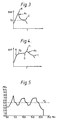
- the repressurisation can be repeated several times (see Figure 5) to confirm the results although some variation will occur in each phase due to the inevitable propagation of the fracture during each pressure phase.
- the linear slope which is observed during the second pressure increase is a measure of the compressibility of a fracture of constant length and therefore provides a measurement of the crack shape once the effect of wellbore compressibility is removed (the compressibility of the wellbore is measured from the pressure response during the injection prior to breakdown). For example, if it is assumed that the crack is radial then: in which V is the volume of fluid in the fracture, P the pressure, E the Young's modulus, v the Poisson's ratio and R the crack radius.
- the time between the fracture re-opening (R) and the pressure increase observed when the fluid reached the crack tip (O) is easily measured. It corresponds to the propagation of a fracture without toughness effect.
- This portion can be used to validate a propagation model because the propagation pressure and the time needed to reach a given length is known. It is also possible to maintain the pressure at a low value once the fluid has reached the tip of the crack and record the fluid loss to measure the permeability and the far-field pore pressure using an injection area larger than the one obtained in a PBU or RFT test.
- An indication of the actual fracture length required to obtain accurate sensible measurements can be determined from situations where fracture toughness can be estimated. For example if K Ic is of the order of 1 MPa ⁇ m, which it often is, and if a ⁇ P of 1 MPa is measured with reasonable accuracy then from (2) above R ⁇ 0.75 m, ie in the order of 1 m as would appear to be necessary with this test geometry in low permeability formations.
- the method of the present invention is conveniently performed using a tool such as that described in US patent number 4860581 and 4936139 which are incorporated herein by reference.
- the tool is a modular tool and includes a hydraulic power source, a packer unit and a pumpout unit.
- a sample chamber which can be connected to the test interval, a sudden pressure drop can be caused in the test interval when a fracture is detected so as to prevent fracture propagation.
- a flow control module can assist in determining the pressures and flow rates for the test interval.
Description
- The present invention relates to a method of performing rock fracture measurements which is particularly useful for making in-situ measurements of stress, fracture toughness and fracture size in a borehole.
- When drilling well boreholes in rock such as in oil exploration, a knowledge of the minimum stress and fracture toughness of the rocks being drilled are important for the planning of the drilling operation and any fracturing operations prior to production from the well. The fracture currently used to measure minimum stress in such circumstances is known as micro-hydraulic fracture (µHF). In µHF a short section of the borehole or well, the test interval, is isolated using inflatable packers. A fluid is then injected into the interval using pump at surface level while the pressure is monitored. A typical borehole pressure (BHP) v. time (T) plot for µHF is shown in Figure 1. The pressure in the interval is increased until a tensile fracture is initiated. This is often recognised by a sharp fall in pressure gradient (B), known as the breakdown pressure. However, fracture initiation may occur before the breakdown is observed. After breakdown the pressure stabilises (S) during which time the fracture propagates through the rock perpendicular to the rock minimum stress direction. When the pressure stabilises, pumping is ceased and a downhole shut-off tool is used to shut-in the interval in order to minimise any storage effects due to the wellbore and the pressure in the interval is monitored using a downhole pressure sensor. The pressure recorded when the interval is shut-in, the Instantaneous Shut-In Pressure (ISIP) is assumed to provide a good indication of the minimum stress. The closure stress (C) can be estimated from the pressure measurement by determining the point at which the pressure decline deviates from a linear dependence on the square-root of shut-in time.
- Variations on the µHF technique described above include step-rate tests and flow back tests. In the latter, the well is shut-in as before and fluid is allowed to flow back from the interval, typically at 10% of the pump-in rate. Monitoring the pressure during flow back can be used to estimate the pressure at which the fracture closes and hence the minimum stress.
- In the technique described above, the fluid used is usually a low viscosity fluid such as mud or water and typically not more than 400 l are injected into the formation at flow rates of 0.05-1.0 l/s. Several injection/fall off cycles are performed until repeatable results are obtained. This can take up to three hours. However, despite the long time taken, the estimation of minimum stress may include error of the order of several MPa, especially when the formation is permeable such that pressure leaks from the fracture face.
- It is an object of the present invention to provide a method which can be used to make more accurate estimations of minimum stress in a shorter time than with the previously proposed techniques.
- According to the present invention, there is provided a method of performing rock fracture measurements in a borehole, comprising isolating a portion of the borehole and alternately pumping a fluid into and removing fluid from said portion so as to increase and decrease the pressure therein respectively while continuously monitoring the fluid pressure in the portion, characterised in that the fluid is pumped into the portion until the initiation of a fracture is indicated, immediately after which fluid is pumped out of the portion so as to prevent propagation of the fracture and allow closure thereof, the portion then being repressurised by pumping fluid back in.
- By pumping out when the fracture is initiated, propagation is substantially prevented allowing estimation of the fracture length and toughness to be obtained during repressurisation and the time taken for the measurement reduced.
- Where appropriate, the pumping in and out can be repeated to obtain several measurements. The pump out rate is preferably the same as the pump in rate and is typically 1-100 x 10⁻⁴ litre/sec⁻¹ for low permeability formations.
- The fracture should be kept as short as possible, typically no greater than about 1 m in length.
- Pumping in and out is preferably achieved using a constant displacement pump. For accurate control, the pump can be a downhole pump, immediately adjacent the test interval.
- The present invention will now be described by way of example, with reference to the accompanying drawings, in which:
- Figure 1 shows a typical plot of borehole pressure (BHP) against time (T) for a conventional µHF test;
- Figure 2 shows a diagramatic view of an apparatus for performing a method according to the invention;
- Figure 3 shows a typical BHP vs T plot for the initial fracture and pump-out phase of a method according to the invention;
- Figure 4 shows a typical BHP vs T plot for a repressurisation and pump back subsequent to that shown in Figure 3;
- Figure 5 shows a BHP (MPa) vs T (min) plot for an experimental use of the method, and
- Figure 6 shows a more detailed practical example corresponding to Figure 4.
- Figure 2 shows a typical µHF tool comprising a
tubing line 10 connected to a pump (not shown) for a fracturing fluid such as mud or water.Packer modules tube line 10 for isolating aninterval 16 of theborehole 18. The portion of theline 10 between thepackers injection ports 22 to allow fluid to be pumped into or out of thetest interval 16. By inflating thepackers fracture 20 can be created. Although not shown, the pump and a pressure sensor are preferably mounted on theline 10 immediately adjacent the tool to reduce response time and minimise any tube line storage effect and increase accuracy as less fluid must be injected or removed to effect a noticeable increase or decrease in pressure. - The
test interval 16 has a typical length of 2 feet (60 cm) and eachpacker fracture 20 must remain effectively within this limit. Consequently, a fracture length of the order of 1 m is desired. - Referring now to Figure 3, the test interval is pressurised as with conventional µHF by pumping fluid into the test interval using a constant displacement pump. However, in this case the pump in rate is much lower than usual, typically 10⁻⁴ litre/sec - 100x10⁻⁴ litre/sec. The pressure in the test interval is closely monitored and increases until a fracture is initiated (B) at which time the pressure breakdown is observed. As soon as this point is reached, the pumping direction is reversed so that fluid is withdrawn from the test interval at substantially the same rate as it was pumped in. This is intended to restrict propagation of the fracture to a minimum and at the pumping rates given above, in low permeability formations, the fracture would be expected to propagate at around 1 m/min. Thus to restrict the fracture length to the limits indicated above, the pumping out (PO) should commence within 10-30 seconds of breakdown. The pressure is monitored during the pump-out phase and the pressure at which the fracture closes (C) can be determined form the discontinuity in the pressure decrease which can be seen. The closure stress (C) is a measure of the minimum stress for the formation σ ₃ and the pump back is continued well beyond this to ensure that the fracture is closed and substantially free of fluid.
- After the fracture is closed fully, the test interval is repressurised as shown in Figure 4. The repressurisation is essentially the same as the initial pressurisation but analysis of the pressure changes shows further information about the formation and the fracture. Again fluid is pumped out once breakdown is observed indicating re-initiation of the fracture. In the repressurisation phase, a pressure increase is seen as the interval is pressurised. At a pressure (R) greater than the closure stress, the fluid re-enters the fracture created in the first phase. After (R₂) the pressure stabilises as the fluid penetrates to the end of the existing fracture. The pressure then begins to rise again as the fracture opens (O) until the pressure is sufficient to re-initiate fracturing (pi) at which point pump back is commenced as before and closure effected. The repressurisation can be repeated several times (see Figure 5) to confirm the results although some variation will occur in each phase due to the inevitable propagation of the fracture during each pressure phase.
- The linear slope which is observed during the second pressure increase is a measure of the compressibility of a fracture of constant length and therefore provides a measurement of the crack shape once the effect of wellbore compressibility is removed (the compressibility of the wellbore is measured from the pressure response during the injection prior to breakdown). For example, if it is assumed that the crack is radial then:

in which V is the volume of fluid in the fracture, P the pressure, E the Young's modulus, v the Poisson's ratio and R the crack radius. Once the crack size has been determined, the re-initiation pressure pi and the value of σ₃ determined previously is used to compute the fracture toughness:

This approach has been tested on a shale which provided a measurement of KIc of 0.4 MPa √m which is in agreement with the known fracture toughness of the rock tested. - During the second injection test, the time between the fracture re-opening (R) and the pressure increase observed when the fluid reached the crack tip (O) is easily measured. It corresponds to the propagation of a fracture without toughness effect. This portion can be used to validate a propagation model because the propagation pressure and the time needed to reach a given length is known. It is also possible to maintain the pressure at a low value once the fluid has reached the tip of the crack and record the fluid loss to measure the permeability and the far-field pore pressure using an injection area larger than the one obtained in a PBU or RFT test.
- These analyses can be performed at each injection test (although the influence of the fracture toughness will be more and more negligible) allowing the determinations to be checked. Measurements using a series of injections, and therefore of various crack lengths allow the pressure response to be interpreted with a more elaborate model (eg elliptical crack shape).
- An indication of the actual fracture length required to obtain accurate sensible measurements can be determined from situations where fracture toughness can be estimated. For example if KIc is of the order of 1 MPa √m, which it often is, and if a ΔP of 1 MPa is measured with reasonable accuracy then from (2) above R ≃ 0.75 m, ie in the order of 1 m as would appear to be necessary with this test geometry in low permeability formations.
- The method of the present invention is conveniently performed using a tool such as that described in US patent number 4860581 and 4936139 which are incorporated herein by reference.
- In each case, the tool is a modular tool and includes a hydraulic power source, a packer unit and a pumpout unit. By including a sample chamber which can be connected to the test interval, a sudden pressure drop can be caused in the test interval when a fracture is detected so as to prevent fracture propagation. A flow control module can assist in determining the pressures and flow rates for the test interval.
- Modification of the tools to accommodate the pressure requirements in use may be required.
Claims (12)
- A method of performing rock fracture measurements in a borehole comprising isolating a portion of the borehole and alternately pumping a fluid into and removing fluid from said portion so as to increase and decrease the pressure therein respectively while continuously monitoring the fluid pressure in the portion as a function of time; characterised in that the fluid is pumped into the portion until the initiation of a fracture, immediately after which fluid is pumped out of the portion so as to prevent propagation of the fracture and allow closure thereof, the portion then being repressurised by pumping fluid back in.
- A method as claimed in claim 1, wherein the pumping-out and repressurising steps are repeated.
- A method as claimed in claim 1 or 2, wherein pumping-out is commenced before the fracture has propagated substantially beyond the influence of the test portion.
- A method as claimed in any preceding claim, wherein the fracture has a length of about 1 m.
- A method as claimed in any preceding claim, wherein pumping back is performed within about 30 seconds of fracture initiation being detected.
- A method as claimed in any preceding claim, wherein the pumping-out is performed at substantially the same rate as the pumping-in.
- A method as claimed in any preceding claim, wherein the pump-in and pump-out rates are 1-100x10⁻⁴ litre/sec.
- A method as claimed in any preceding claim, wherein pumping-in and pumping-out are performed downhole.
- A method as claimed in any preceding claim wherein the isolated portion is defined in uncased borehole.
- A method as claimed in any preceding claim when used to measure the minimum stress and fracture toughness of the formation.
- A method as claimed in claim 10, where the pressure at which the fracture closes is measured to determine the minimum stress.
- A method as claimed in claim 11, wherein the pressure at which the fracture propagates on repressurisation of the test interval is measured and used to calculate the fracture length and toughness.
Applications Claiming Priority (2)
| Application Number | Priority Date | Filing Date | Title |
|---|---|---|---|
| GB9026703 | 1990-12-07 | ||
| GB909026703A GB9026703D0 (en) | 1990-12-07 | 1990-12-07 | Downhole measurement using very short fractures |
Publications (2)
| Publication Number | Publication Date |
|---|---|
| EP0490421A1 EP0490421A1 (en) | 1992-06-17 |
| EP0490421B1 true EP0490421B1 (en) | 1994-12-14 |
Family
ID=10686686
Family Applications (1)
| Application Number | Title | Priority Date | Filing Date |
|---|---|---|---|
| EP91203098A Expired - Lifetime EP0490421B1 (en) | 1990-12-07 | 1991-11-27 | Downhole measurements using very short fractures |
Country Status (6)
| Country | Link |
|---|---|
| US (1) | US5165276A (en) |
| EP (1) | EP0490421B1 (en) |
| CA (1) | CA2056966C (en) |
| DE (1) | DE69105933D1 (en) |
| GB (2) | GB9026703D0 (en) |
| NO (1) | NO303152B1 (en) |
Families Citing this family (34)
| Publication number | Priority date | Publication date | Assignee | Title |
|---|---|---|---|---|
| GB9114972D0 (en) * | 1991-07-11 | 1991-08-28 | Schlumberger Ltd | Fracturing method and apparatus |
| US5353637A (en) * | 1992-06-09 | 1994-10-11 | Plumb Richard A | Methods and apparatus for borehole measurement of formation stress |
| US5287741A (en) * | 1992-08-31 | 1994-02-22 | Halliburton Company | Methods of perforating and testing wells using coiled tubing |
| US5413179A (en) * | 1993-04-16 | 1995-05-09 | The Energex Company | System and method for monitoring fracture growth during hydraulic fracture treatment |
| US5322126A (en) * | 1993-04-16 | 1994-06-21 | The Energex Company | System and method for monitoring fracture growth during hydraulic fracture treatment |
| US5635712A (en) * | 1995-05-04 | 1997-06-03 | Halliburton Company | Method for monitoring the hydraulic fracturing of a subterranean formation |
| US5703286A (en) * | 1995-10-20 | 1997-12-30 | Halliburton Energy Services, Inc. | Method of formation testing |
| US5743334A (en) * | 1996-04-04 | 1998-04-28 | Chevron U.S.A. Inc. | Evaluating a hydraulic fracture treatment in a wellbore |
| WO1999045236A1 (en) * | 1998-03-06 | 1999-09-10 | Baker Hughes Incorporated | Formation testing apparatus and method |
| EP1381755B1 (en) | 2000-07-20 | 2007-12-26 | Baker Hughes Incorporated | Drawdown apparatus and method for in-situ analysis of formation fluids |
| US7032661B2 (en) | 2001-07-20 | 2006-04-25 | Baker Hughes Incorporated | Method and apparatus for combined NMR and formation testing for assessing relative permeability with formation testing and nuclear magnetic resonance testing |
| US7126332B2 (en) | 2001-07-20 | 2006-10-24 | Baker Hughes Incorporated | Downhole high resolution NMR spectroscopy with polarization enhancement |
| US7011155B2 (en) | 2001-07-20 | 2006-03-14 | Baker Hughes Incorporated | Formation testing apparatus and method for optimizing draw down |
| US7395703B2 (en) | 2001-07-20 | 2008-07-08 | Baker Hughes Incorporated | Formation testing apparatus and method for smooth draw down |
| US6832515B2 (en) | 2002-09-09 | 2004-12-21 | Schlumberger Technology Corporation | Method for measuring formation properties with a time-limited formation test |
| US7234521B2 (en) | 2003-03-10 | 2007-06-26 | Baker Hughes Incorporated | Method and apparatus for pumping quality control through formation rate analysis techniques |
| US20070215345A1 (en) * | 2006-03-14 | 2007-09-20 | Theodore Lafferty | Method And Apparatus For Hydraulic Fracturing And Monitoring |
| KR100925266B1 (en) * | 2006-10-31 | 2009-11-05 | 한국지질자원연구원 | Apparatus for measuring in-situ stress of rock using thermal crack |
| US8146416B2 (en) * | 2009-02-13 | 2012-04-03 | Schlumberger Technology Corporation | Methods and apparatus to perform stress testing of geological formations |
| US8047284B2 (en) * | 2009-02-27 | 2011-11-01 | Halliburton Energy Services, Inc. | Determining the use of stimulation treatments based on high process zone stress |
| US20130180722A1 (en) * | 2009-12-04 | 2013-07-18 | Schlumberger Technology Corporation | Technique of fracturing with selective stream injection |
| PL400952A1 (en) * | 2009-12-09 | 2013-05-27 | Schlumberger Technology B.V. | Method for enlarging the area of fracturing |
| US20110168389A1 (en) * | 2010-01-08 | 2011-07-14 | Meijs Raymund J | Surface Controlled Downhole Shut-In Valve |
| US9243486B2 (en) * | 2013-02-25 | 2016-01-26 | Baker Hughes Incorporated | Apparatus and method for determining closure pressure from flowback measurements of a fractured formation |
| US9702247B2 (en) | 2013-09-17 | 2017-07-11 | Halliburton Energy Services, Inc. | Controlling an injection treatment of a subterranean region based on stride test data |
| US9500076B2 (en) * | 2013-09-17 | 2016-11-22 | Halliburton Energy Services, Inc. | Injection testing a subterranean region |
| US9574443B2 (en) * | 2013-09-17 | 2017-02-21 | Halliburton Energy Services, Inc. | Designing an injection treatment for a subterranean region based on stride test data |
| US9976402B2 (en) * | 2014-09-18 | 2018-05-22 | Baker Hughes, A Ge Company, Llc | Method and system for hydraulic fracture diagnosis with the use of a coiled tubing dual isolation service tool |
| WO2017095252A1 (en) | 2015-11-30 | 2017-06-08 | Шлюмберже Текнолоджи Корпорейшн | Method for determining fracture closure pressure in a formation |
| CN106546479A (en) * | 2017-02-06 | 2017-03-29 | 江苏拓创科研仪器有限公司 | Fracture caused by hydraulic pressure sharing lood assay device |
| US10738600B2 (en) * | 2017-05-19 | 2020-08-11 | Baker Hughes, A Ge Company, Llc | One run reservoir evaluation and stimulation while drilling |
| US10557345B2 (en) | 2018-05-21 | 2020-02-11 | Saudi Arabian Oil Company | Systems and methods to predict and inhibit broken-out drilling-induced fractures in hydrocarbon wells |
| US10753203B2 (en) | 2018-07-10 | 2020-08-25 | Saudi Arabian Oil Company | Systems and methods to identify and inhibit spider web borehole failure in hydrocarbon wells |
| CN113533680A (en) * | 2020-04-16 | 2021-10-22 | 中国石油化工股份有限公司 | Experimental device and method for simulating underground temporary plugging fracturing experiment |
Family Cites Families (16)
| Publication number | Priority date | Publication date | Assignee | Title |
|---|---|---|---|---|
| US3602308A (en) * | 1969-08-26 | 1971-08-31 | Amoco Prod Co | Hydraulically fracturing an isolated zone of an unconsolidated formation |
| US4398416A (en) * | 1979-08-31 | 1983-08-16 | Standard Oil Company (Indiana) | Determination of fracturing fluid loss rate from pressure decline curve |
| FR2467414A1 (en) * | 1979-10-11 | 1981-04-17 | Anvar | METHOD AND DEVICE FOR RECOGNIZING SOILS AND ROCKY MEDIA |
| US4372380A (en) * | 1981-02-27 | 1983-02-08 | Standard Oil Company (Indiana) | Method for determination of fracture closure pressure |
| US4453595A (en) * | 1982-09-07 | 1984-06-12 | Maxwell Laboratories, Inc. | Method of measuring fracture pressure in underground formations |
| EP0146324A3 (en) * | 1983-12-20 | 1986-07-09 | Shosei Serata | Method and apparatus for measuring in situ earthen stresses and properties using a borehole probe |
| FR2566834B1 (en) * | 1984-06-29 | 1986-11-14 | Inst Francais Du Petrole | METHOD FOR DETERMINING AT LEAST ONE CHARACTERISTIC SIZE OF A GEOLOGICAL FORMATION, IN PARTICULAR THE TENACITY OF THIS FORMATION |
| JPS6250591A (en) * | 1985-08-29 | 1987-03-05 | 東北大学長 | Crust stress measuring method by water pressure crushing method based on evaluation of crack behavior in rock |
| US4836280A (en) * | 1987-09-29 | 1989-06-06 | Halliburton Company | Method of evaluating subsurface fracturing operations |
| US4793413A (en) * | 1987-12-21 | 1988-12-27 | Amoco Corporation | Method for determining formation parting pressure |
| US4848461A (en) * | 1988-06-24 | 1989-07-18 | Halliburton Company | Method of evaluating fracturing fluid performance in subsurface fracturing operations |
| DE3823495A1 (en) * | 1988-07-12 | 1990-01-18 | Koezponti Banyaszati Fejleszte | HYDRAULIC STONE-DRILLING HOLE HOLE PROBE AND METHOD FOR ITS USE |
| US4936139A (en) * | 1988-09-23 | 1990-06-26 | Schlumberger Technology Corporation | Down hole method for determination of formation properties |
| US4860581A (en) * | 1988-09-23 | 1989-08-29 | Schlumberger Technology Corporation | Down hole tool for determination of formation properties |
| US5050674A (en) * | 1990-05-07 | 1991-09-24 | Halliburton Company | Method for determining fracture closure pressure and fracture volume of a subsurface formation |
| US5005643A (en) * | 1990-05-11 | 1991-04-09 | Halliburton Company | Method of determining fracture parameters for heterogenous formations |
-
1990
- 1990-12-07 GB GB909026703A patent/GB9026703D0/en active Pending
-
1991
- 1991-11-27 EP EP91203098A patent/EP0490421B1/en not_active Expired - Lifetime
- 1991-11-27 GB GB9125207A patent/GB2250602B/en not_active Expired - Lifetime
- 1991-11-27 DE DE69105933T patent/DE69105933D1/en not_active Expired - Lifetime
- 1991-12-04 US US07/802,388 patent/US5165276A/en not_active Expired - Lifetime
- 1991-12-04 CA CA002056966A patent/CA2056966C/en not_active Expired - Lifetime
- 1991-12-06 NO NO914821A patent/NO303152B1/en unknown
Also Published As
| Publication number | Publication date |
|---|---|
| GB2250602A (en) | 1992-06-10 |
| GB2250602B (en) | 1994-06-15 |
| EP0490421A1 (en) | 1992-06-17 |
| GB9125207D0 (en) | 1992-01-29 |
| GB9026703D0 (en) | 1991-01-23 |
| CA2056966A1 (en) | 1992-06-08 |
| NO914821L (en) | 1992-06-09 |
| NO914821D0 (en) | 1991-12-06 |
| US5165276A (en) | 1992-11-24 |
| DE69105933D1 (en) | 1995-01-26 |
| NO303152B1 (en) | 1998-06-02 |
| CA2056966C (en) | 2000-04-18 |
Similar Documents
| Publication | Publication Date | Title |
|---|---|---|
| EP0490421B1 (en) | Downhole measurements using very short fractures | |
| US7031841B2 (en) | Method for determining pressure of earth formations | |
| CA2034444C (en) | Method and apparatus for the determination of formation fluid flow rates and reservoir deliverability | |
| US8899349B2 (en) | Methods for determining formation strength of a wellbore | |
| US5184508A (en) | Method for determining formation pressure | |
| US5095745A (en) | Method and apparatus for testing subsurface formations | |
| US5295393A (en) | Fracturing method and apparatus | |
| US8418546B2 (en) | In-situ fluid compatibility testing using a wireline formation tester | |
| US7774140B2 (en) | Method and an apparatus for detecting fracture with significant residual width from previous treatments | |
| US7753117B2 (en) | Tool and method for evaluating fluid dynamic properties of a cement annulus surrounding a casing | |
| US8909478B2 (en) | Method for calculating the ratio of relative permeabilities of formation fluids and wettability of a formation downhole, and a formation testing tool to implement the same | |
| US7753118B2 (en) | Method and tool for evaluating fluid dynamic properties of a cement annulus surrounding a casing | |
| Daneshy et al. | In-situ stress measurements during drilling | |
| US6378363B1 (en) | Method for obtaining leak-off test and formation integrity test profiles from limited downhole pressure measurements | |
| Thiercelin et al. | A new wireline tool for in-situ stress measurements | |
| US5492175A (en) | Method for determining closure of a hydraulically induced in-situ fracture | |
| US8371161B2 (en) | Apparatus and method for formation testing | |
| US5272916A (en) | Methods of detecting and measuring in-situ elastic anisotropy in subterranean formations | |
| Ray | Thiercelin & Desroches (1993) have analyzed the condition needed to successfully carry out stress tests in low permeability rocks. Some of these con-ditions are:-to inject the fracturing uid at extremely low | |
| ITO | The baby borehole hydrofracturing method for deep stress measurements | |
| Alekseenko et al. | Inverse Problems in Hydraulic Fracturing |
Legal Events
| Date | Code | Title | Description |
|---|---|---|---|
| PUAI | Public reference made under article 153(3) epc to a published international application that has entered the european phase |
Free format text: ORIGINAL CODE: 0009012 |
|
| AK | Designated contracting states |
Kind code of ref document: A1 Designated state(s): DE DK FR IT NL |
|
| 17P | Request for examination filed |
Effective date: 19920629 |
|
| 17Q | First examination report despatched |
Effective date: 19940126 |
|
| GRAA | (expected) grant |
Free format text: ORIGINAL CODE: 0009210 |
|
| AK | Designated contracting states |
Kind code of ref document: B1 Designated state(s): DE DK FR IT NL |
|
| PG25 | Lapsed in a contracting state [announced via postgrant information from national office to epo] |
Ref country code: IT Free format text: LAPSE BECAUSE OF FAILURE TO SUBMIT A TRANSLATION OF THE DESCRIPTION OR TO PAY THE FEE WITHIN THE PRE;WARNING: LAPSES OF ITALIAN PATENTS WITH EFFECTIVE DATE BEFORE 2007 MAY HAVE OCCURRED AT ANY TIME BEFORE 2007. THE CORRECT EFFECTIVE DATE MAY BE DIFFERENT FROM THE ONE RECORDED.SCRIBED TIME-LIMIT Effective date: 19941214 Ref country code: DK Effective date: 19941214 |
|
| REF | Corresponds to: |
Ref document number: 69105933 Country of ref document: DE Date of ref document: 19950126 |
|
| PG25 | Lapsed in a contracting state [announced via postgrant information from national office to epo] |
Ref country code: DE Effective date: 19950315 |
|
| ET | Fr: translation filed | ||
| K2C3 | Correction of patent specification (complete document) published |
Effective date: 19941214 |
|
| PLBE | No opposition filed within time limit |
Free format text: ORIGINAL CODE: 0009261 |
|
| STAA | Information on the status of an ep patent application or granted ep patent |
Free format text: STATUS: NO OPPOSITION FILED WITHIN TIME LIMIT |
|
| 26N | No opposition filed | ||
| PGFP | Annual fee paid to national office [announced via postgrant information from national office to epo] |
Ref country code: FR Payment date: 20031110 Year of fee payment: 13 |
|
| PGFP | Annual fee paid to national office [announced via postgrant information from national office to epo] |
Ref country code: NL Payment date: 20041103 Year of fee payment: 14 |
|
| PG25 | Lapsed in a contracting state [announced via postgrant information from national office to epo] |
Ref country code: FR Free format text: LAPSE BECAUSE OF NON-PAYMENT OF DUE FEES Effective date: 20050729 |
|
| REG | Reference to a national code |
Ref country code: FR Ref legal event code: ST |
|
| PG25 | Lapsed in a contracting state [announced via postgrant information from national office to epo] |
Ref country code: NL Free format text: LAPSE BECAUSE OF NON-PAYMENT OF DUE FEES Effective date: 20060601 |
|
| NLV4 | Nl: lapsed or anulled due to non-payment of the annual fee |
Effective date: 20060601 |