EP0490292B1 - Light irradiating apparatus having light emitting diode used as light source - Google Patents
Light irradiating apparatus having light emitting diode used as light source Download PDFInfo
- Publication number
- EP0490292B1 EP0490292B1 EP91120976A EP91120976A EP0490292B1 EP 0490292 B1 EP0490292 B1 EP 0490292B1 EP 91120976 A EP91120976 A EP 91120976A EP 91120976 A EP91120976 A EP 91120976A EP 0490292 B1 EP0490292 B1 EP 0490292B1
- Authority
- EP
- European Patent Office
- Prior art keywords
- light
- light source
- light emitting
- motorcar
- emitting units
- Prior art date
- Legal status (The legal status is an assumption and is not a legal conclusion. Google has not performed a legal analysis and makes no representation as to the accuracy of the status listed.)
- Expired - Lifetime
Links
Images

Classifications
-
- G—PHYSICS
- G01—MEASURING; TESTING
- G01S—RADIO DIRECTION-FINDING; RADIO NAVIGATION; DETERMINING DISTANCE OR VELOCITY BY USE OF RADIO WAVES; LOCATING OR PRESENCE-DETECTING BY USE OF THE REFLECTION OR RERADIATION OF RADIO WAVES; ANALOGOUS ARRANGEMENTS USING OTHER WAVES
- G01S7/00—Details of systems according to groups G01S13/00, G01S15/00, G01S17/00
- G01S7/48—Details of systems according to groups G01S13/00, G01S15/00, G01S17/00 of systems according to group G01S17/00
- G01S7/481—Constructional features, e.g. arrangements of optical elements
- G01S7/4818—Constructional features, e.g. arrangements of optical elements using optical fibres
-
- G—PHYSICS
- G01—MEASURING; TESTING
- G01S—RADIO DIRECTION-FINDING; RADIO NAVIGATION; DETERMINING DISTANCE OR VELOCITY BY USE OF RADIO WAVES; LOCATING OR PRESENCE-DETECTING BY USE OF THE REFLECTION OR RERADIATION OF RADIO WAVES; ANALOGOUS ARRANGEMENTS USING OTHER WAVES
- G01S17/00—Systems using the reflection or reradiation of electromagnetic waves other than radio waves, e.g. lidar systems
- G01S17/88—Lidar systems specially adapted for specific applications
- G01S17/93—Lidar systems specially adapted for specific applications for anti-collision purposes
- G01S17/931—Lidar systems specially adapted for specific applications for anti-collision purposes of land vehicles
-
- G—PHYSICS
- G01—MEASURING; TESTING
- G01S—RADIO DIRECTION-FINDING; RADIO NAVIGATION; DETERMINING DISTANCE OR VELOCITY BY USE OF RADIO WAVES; LOCATING OR PRESENCE-DETECTING BY USE OF THE REFLECTION OR RERADIATION OF RADIO WAVES; ANALOGOUS ARRANGEMENTS USING OTHER WAVES
- G01S7/00—Details of systems according to groups G01S13/00, G01S15/00, G01S17/00
- G01S7/48—Details of systems according to groups G01S13/00, G01S15/00, G01S17/00 of systems according to group G01S17/00
- G01S7/481—Constructional features, e.g. arrangements of optical elements
- G01S7/4814—Constructional features, e.g. arrangements of optical elements of transmitters alone
-
- G—PHYSICS
- G02—OPTICS
- G02B—OPTICAL ELEMENTS, SYSTEMS OR APPARATUS
- G02B6/00—Light guides; Structural details of arrangements comprising light guides and other optical elements, e.g. couplings
- G02B6/04—Light guides; Structural details of arrangements comprising light guides and other optical elements, e.g. couplings formed by bundles of fibres
- G02B6/06—Light guides; Structural details of arrangements comprising light guides and other optical elements, e.g. couplings formed by bundles of fibres the relative position of the fibres being the same at both ends, e.g. for transporting images
-
- G—PHYSICS
- G02—OPTICS
- G02B—OPTICAL ELEMENTS, SYSTEMS OR APPARATUS
- G02B6/00—Light guides; Structural details of arrangements comprising light guides and other optical elements, e.g. couplings
- G02B6/24—Coupling light guides
- G02B6/42—Coupling light guides with opto-electronic elements
- G02B6/4201—Packages, e.g. shape, construction, internal or external details
- G02B6/4204—Packages, e.g. shape, construction, internal or external details the coupling comprising intermediate optical elements, e.g. lenses, holograms
- G02B6/4206—Optical features
-
- G—PHYSICS
- G02—OPTICS
- G02B—OPTICAL ELEMENTS, SYSTEMS OR APPARATUS
- G02B6/00—Light guides; Structural details of arrangements comprising light guides and other optical elements, e.g. couplings
- G02B6/24—Coupling light guides
- G02B6/42—Coupling light guides with opto-electronic elements
- G02B6/4201—Packages, e.g. shape, construction, internal or external details
- G02B6/4249—Packages, e.g. shape, construction, internal or external details comprising arrays of active devices and fibres
-
- G—PHYSICS
- G02—OPTICS
- G02B—OPTICAL ELEMENTS, SYSTEMS OR APPARATUS
- G02B6/00—Light guides; Structural details of arrangements comprising light guides and other optical elements, e.g. couplings
- G02B6/24—Coupling light guides
- G02B6/42—Coupling light guides with opto-electronic elements
- G02B6/4298—Coupling light guides with opto-electronic elements coupling with non-coherent light sources and/or radiation detectors, e.g. lamps, incandescent bulbs, scintillation chambers
-
- G—PHYSICS
- G01—MEASURING; TESTING
- G01S—RADIO DIRECTION-FINDING; RADIO NAVIGATION; DETERMINING DISTANCE OR VELOCITY BY USE OF RADIO WAVES; LOCATING OR PRESENCE-DETECTING BY USE OF THE REFLECTION OR RERADIATION OF RADIO WAVES; ANALOGOUS ARRANGEMENTS USING OTHER WAVES
- G01S7/00—Details of systems according to groups G01S13/00, G01S15/00, G01S17/00
- G01S7/48—Details of systems according to groups G01S13/00, G01S15/00, G01S17/00 of systems according to group G01S17/00
- G01S7/481—Constructional features, e.g. arrangements of optical elements
- G01S7/4814—Constructional features, e.g. arrangements of optical elements of transmitters alone
- G01S7/4815—Constructional features, e.g. arrangements of optical elements of transmitters alone using multiple transmitters
-
- G—PHYSICS
- G01—MEASURING; TESTING
- G01S—RADIO DIRECTION-FINDING; RADIO NAVIGATION; DETERMINING DISTANCE OR VELOCITY BY USE OF RADIO WAVES; LOCATING OR PRESENCE-DETECTING BY USE OF THE REFLECTION OR RERADIATION OF RADIO WAVES; ANALOGOUS ARRANGEMENTS USING OTHER WAVES
- G01S7/00—Details of systems according to groups G01S13/00, G01S15/00, G01S17/00
- G01S7/48—Details of systems according to groups G01S13/00, G01S15/00, G01S17/00 of systems according to group G01S17/00
- G01S7/491—Details of non-pulse systems
- G01S7/4911—Transmitters
Definitions
- the present invention relates to a light irradiating apparatus for an optical radar system.
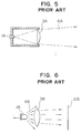
- a conventional optical radar system as well as a conventional light irradiating apparatus having a light emitting diode used therefor as a light source will briefly be described below with reference to Figs. 5 and 6.
- Fig. 5 is a schematic side view of a conventional optical radar system which has been developed as an apparatus for measuring a distance from a motorcar running ahead of a rear motorcar.
- reference numeral 1A designates a light source
- reference numeral 3A designates a light irradiating lens
- reference numeral 4A designates an emitted light.
- the light source 1A having a certain small surface is arranged at the position coincident with the focus of the light irradiating lens 3A.
- the light outputted from the light source 1A becomes an emitted light 4A which propagates while gradually radially expanding after it has permeated through the light irradiating lens 3A.
- the motorcar running ahead,of the rear motorcar is located remote from the rear motorcar, the emitted light 4A sufficiently radially expands during its propagation, whereby a reflective plate mounted on the rear part of the motorcar running ahead of the rear motorcar is reliably illuminated with the emitted light 4A.
- the motorcar running ahead of the rear motorcar can visually be recognized by a driver on the rear motorcar, and moreover, a distance between both the motorcars can be measured with excellent accuracy by measuring the time that elapses from the point of time when the light is reflected at the reflective plate till the point of time when the reflected light returns to the rear motorcar, by using suitable measuring means mounted on the rear motorcar.
- Fig. 6 is a schematic side view of a conventional light emitting apparatus having a light emitting diode used therefor as a light source (hereinafter referred to simply as a LED light emitting apparatus) for projecting a substantially parallel light onto a screen or the like while a light emitting diode is used as a light source.
- reference numeral 1B designates a light emitting diode light source (hereinafter referred to simply as a LED light source)
- reference numeral 3B designates a light irradiating lens
- reference numeral 4B designates an emitted light
- reference numeral 5B designates a screen.
- the LED light source 1B for emitting a light from the whole surface thereof With respect to the LED light source 1B for emitting a light from the whole surface thereof, a difference in optical intensity of the emitted light 4A arises depending on the positions where wire bonding portions and tip end portions are arranged. For this reason, even when the emitted light beam 4B outputted from the LED light source 1B is transformed into a substantially parallel light via the light irradiating lens 3B, the light 4B having fluctuation in optical intensity thereof is projected onto the screen 12B or the like while it is adversely affected by a pattern of emission of the light 4B from the LED light source 1B.
- the LED light source 1B has a large light emission angle, an optical system associated with the light irradiating lens 3B becomes unavoidably complicated in structure when the emitted light 4B is intended to be transformed into a substantially parallel light at a high optical efficiency.
- a light irradiating apparatus for an optical radar system comprising a plurality of light emitting units so as to emit a narrow beam by activating part of said light emitting units or a wide beam by activating all said light emitting units.
- a light irradiating apparatus for an optical radar system according to the present invention is defined by claim 1.
- a motor car running ahead of a rear motor car can be irradiated by the narrow beam or the wide beam according to the driver's choice.
- An example for the choice is that first the motor car running ahead is irradiated by the wide beam so as to detect a portion to be needed, and second said portion of the motor car running ahead is concentrically irradiated by the narrow beam.
- US-Patent 4 914 747 shows a vehicular projector-type headlamp having upper and lower reflector parts and two light sources disposed one behind the other on a common axis, one of said light sources being positioned at the first focus of the upper reflector part, and the other light source being positioned at the first focus of the lower reflector part.
- DE-C-1 162 787 shows in Fig. 10 a head lamp particularly for motorcars comprising a plurality of light producing units which can be activated individually or in common and which are disposed in a circular pattern in the center of which a blinker lamp is provided.
- Fig. 1 is a perspective view of a light source employable for an optical radar system in accordance with an embodiment of the present invention.
- the light source designated by reference numeral 1 is constituted by seven light emitting units 2 in such a manner that one of them is located at the central part of the light source 1 and the remaining six light emitting units 2 are circumferentially arranged around the central light emitting unit 2 in the side-by-side relationship.
- the light source 1 constructed as described above, only the central light emitting unit 2 may be activated. Alternatively, all the seven light emitting units 2 may be activated simultaneously.
- infrared ray emitting diodes or the like are employed for the light emitting units 2.
- the light source 1 is located at the position coincident to the focus of a light irradiating lens 3, and an emitted light 4 generated when only the central light emitting unit 2 is activated becomes a narrow beam which advances from the light source 1 while gradually radially expanding after it has permeated through the light irradiating lens 3 in the same manner as the conventional LED light source 1A which has been described above with reference to Fig. 6.
- an emitted light 5 generated when all the seven light emitting units 2 are simultaneously activated becomes a wide beam which advances from the light source 1 while largely radially expanding after it has permeated through the light irradiating lens 3, because the light emitting section has a wide working surface and a some light component is irradiated from the position comparatively largely offset from an optical axis of the light source 1.
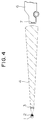
- a largely radially expanding wide light 5 is emitted from the light source 1 by activating all the seven light emitting units 2 so that a wide range inclusive of a reflective plate 7 mounted the rear end of the motorcar 6 is illuminated with the wide beam.
- a distance between the two motorcars is sufficiently long as shown in Fig. 4
- only the central light emitting unit 2 is activated to generate a slightly radially expanding narrow beam 4.
- the narrow beam 4 since the narrow beam 4 has sufficiently large radial expansion until it reaches the motorcar 6 running ahead of the rear motorcar, the reflective plate 7 on the rear end of the motorcar 6 can reliably be illuminated even with the narrow beam 4.
- the motorcar 6 running ahead of the rear motorcar can reliably visually be sensed by a driver on the rear motorcar regardless of a distance between the two motorcars by properly changing the working surface of the light emitting section of the light source 1 depending on the distance between the two motorcars.
- the time that elapses from the point of time when the light beam is reflected from the reflective plate 7 on the rear end of the motorcar 6 till the point of time when the reflected light returns to suitable measuring means on the rear motorcar can be measured by this measuring means, the distance between the two motorcars can be determined with high accuracy.
- the present invention should not be limited only to the described embodiment but the number of light emitting units 2 and a manner of arranging them may be determined in proper consideration of various working conditions.
- the light source of the present invention may be used not only as a light source for a conventional light irradiating device or apparatus but also as a light source for a conventional lamp.
Landscapes
- Physics & Mathematics (AREA)
- General Physics & Mathematics (AREA)
- Engineering & Computer Science (AREA)
- Optics & Photonics (AREA)
- Computer Networks & Wireless Communication (AREA)
- Radar, Positioning & Navigation (AREA)
- Remote Sensing (AREA)
- Electromagnetism (AREA)
- Optical Radar Systems And Details Thereof (AREA)
Description
Claims (5)
- A light irradiating apparatus for an optical radar system, said apparatus comprising a light source (1) and a lens (3), said light source (1) being located at a position coincident with the focus of said lens (3), and the light emitted from said light source (1) passing through said lens (3) for irradiating an object, said light source (1) comprising a plurality of light emitting units (2) arranged in such a manner that said light source (1) can emit a narrow beam or a wide beam by activating a part of said light emiting units (2) or all of said light emitting units (2), characterised in that said part of said light emitting units (2) for emitting a narrow beam comprises a single centrally positioned light emitting unit (2), the remaining light emitting units (2) of said plurality of light emitting units (2) being disposed symmetrically around said central light emitting unit.
- A light irradiating apparatus according to claim 1, wherein said light emitting units (2) are arranged substantially perpendicular to the optical axis of said light irradiating apparatus.
- A light irradiating apparatus according to claim 1 or 2, wherein said light source (1) comprises seven light emitting units (2).
- A light irradiating apparatus according to one of claims 1 to 3, wherein said light source (1) is arranged in a manner that its illuminating surface is facing said lens (3).
- A light irradiating apparatus according to claim 4, wherein said illuminating surface of said light source (1) is arranged substantially parallel to said lens (3).
Priority Applications (2)
| Application Number | Priority Date | Filing Date | Title |
|---|---|---|---|
| EP94101001A EP0596866B1 (en) | 1990-12-22 | 1991-12-06 | Optical Fiber |
| EP19940100997 EP0596865A3 (en) | 1990-12-17 | 1991-12-06 | Light irradiating apparatus having light emitting diode used as light source |
Applications Claiming Priority (10)
| Application Number | Priority Date | Filing Date | Title |
|---|---|---|---|
| JP401774/90U | 1990-12-07 | ||
| JP40177490U JPH0487487U (en) | 1990-12-07 | 1990-12-07 | |
| JP40350690U JPH0487802U (en) | 1990-12-17 | 1990-12-17 | |
| JP40350590U JPH0487801U (en) | 1990-12-17 | 1990-12-17 | |
| JP403506/90U | 1990-12-17 | ||
| JP403505/90U | 1990-12-17 | ||
| JP40410190U JPH0491303U (en) | 1990-12-21 | 1990-12-21 | |
| JP404101/90U | 1990-12-21 | ||
| JP1990404364U JPH0491302U (en) | 1990-12-22 | 1990-12-22 | |
| JP404364/90U | 1990-12-22 |
Related Child Applications (4)
| Application Number | Title | Priority Date | Filing Date |
|---|---|---|---|
| EP94101001A Division EP0596866B1 (en) | 1990-12-22 | 1991-12-06 | Optical Fiber |
| EP19940100997 Division EP0596865A3 (en) | 1990-12-17 | 1991-12-06 | Light irradiating apparatus having light emitting diode used as light source |
| EP94100997.9 Division-Into | 1991-12-06 | ||
| EP94101001.9 Division-Into | 1991-12-06 |
Publications (3)
| Publication Number | Publication Date |
|---|---|
| EP0490292A2 EP0490292A2 (en) | 1992-06-17 |
| EP0490292A3 EP0490292A3 (en) | 1993-05-05 |
| EP0490292B1 true EP0490292B1 (en) | 1998-04-01 |
Family
ID=27531353
Family Applications (1)
| Application Number | Title | Priority Date | Filing Date |
|---|---|---|---|
| EP91120976A Expired - Lifetime EP0490292B1 (en) | 1990-12-07 | 1991-12-06 | Light irradiating apparatus having light emitting diode used as light source |
Country Status (2)
| Country | Link |
|---|---|
| EP (1) | EP0490292B1 (en) |
| DE (1) | DE69129182T2 (en) |
Cited By (1)
| Publication number | Priority date | Publication date | Assignee | Title |
|---|---|---|---|---|
| US7360924B2 (en) | 2002-12-02 | 2008-04-22 | 3M Innovative Properties Company | Illumination system using a plurality of light sources |
Families Citing this family (5)
| Publication number | Priority date | Publication date | Assignee | Title |
|---|---|---|---|---|
| IT1256956B (en) * | 1992-10-05 | 1995-12-27 | Gilardini Spa | DEVICE TO DETECT RELATIVE POSITIONS BETWEEN VEHICLES, MAINLY IN ANTI-COLLISION FUNCTION. |
| US6152588A (en) * | 1994-09-28 | 2000-11-28 | Sdl, Inc. | Addressable vehicular lighting system |
| US7250611B2 (en) | 2003-12-02 | 2007-07-31 | 3M Innovative Properties Company | LED curing apparatus and method |
| US7329887B2 (en) * | 2003-12-02 | 2008-02-12 | 3M Innovative Properties Company | Solid state light device |
| DE102019207470A1 (en) * | 2019-05-22 | 2020-11-26 | Robert Bosch Gmbh | LIDAR sensor for optical detection of a field of view and method for optical detection of a field of view |
Citations (1)
| Publication number | Priority date | Publication date | Assignee | Title |
|---|---|---|---|---|
| DE1162787B (en) * | 1961-06-29 | 1964-02-13 | Josef Helmut Danzer | Glare-proof headlights, especially for automobiles |
Family Cites Families (1)
| Publication number | Priority date | Publication date | Assignee | Title |
|---|---|---|---|---|
| JPH07118208B2 (en) * | 1988-06-28 | 1995-12-18 | 株式会社小糸製作所 | Automotive headlights |
-
1991
- 1991-12-06 EP EP91120976A patent/EP0490292B1/en not_active Expired - Lifetime
- 1991-12-06 DE DE69129182T patent/DE69129182T2/en not_active Expired - Fee Related
Patent Citations (1)
| Publication number | Priority date | Publication date | Assignee | Title |
|---|---|---|---|---|
| DE1162787B (en) * | 1961-06-29 | 1964-02-13 | Josef Helmut Danzer | Glare-proof headlights, especially for automobiles |
Cited By (2)
| Publication number | Priority date | Publication date | Assignee | Title |
|---|---|---|---|---|
| US7360924B2 (en) | 2002-12-02 | 2008-04-22 | 3M Innovative Properties Company | Illumination system using a plurality of light sources |
| US7658526B2 (en) | 2002-12-02 | 2010-02-09 | 3M Innovative Properties Company | Illumination system using a plurality of light sources |
Also Published As
| Publication number | Publication date |
|---|---|
| EP0490292A2 (en) | 1992-06-17 |
| DE69129182T2 (en) | 1998-09-03 |
| DE69129182D1 (en) | 1998-05-07 |
| EP0490292A3 (en) | 1993-05-05 |
Similar Documents
| Publication | Publication Date | Title |
|---|---|---|
| US6499870B1 (en) | Tail light for a motor vehicle | |
| CN105465713B (en) | Luminous lighting and/or signalling module for a motor vehicle | |
| US5257173A (en) | Light irradiating apparatus having light emitting diode used as light source | |
| CN113167454B (en) | Lighting device for vehicle | |
| EP4174368B1 (en) | Vehicle lighting device | |
| JP2000215710A (en) | Multifunctional taillight device for vehicles | |
| KR102953560B1 (en) | Lamp for vehicle | |
| US20020044454A1 (en) | Light-emitting diode combination marker/clearance lamp for trucks and trailers | |
| US10612743B2 (en) | Vehicle lamp | |
| EP4321794B1 (en) | Illumination module for a vehicle lamp with multi light sources and headlight having the same | |
| CN111853691A (en) | Integrated LIDAR light device for a vehicle | |
| WO2017075506A1 (en) | Methods and apparatus for intrinsically safe laser sourced illumination | |
| EP0596865A2 (en) | Light irradiating apparatus having light emitting diode used as light source | |
| US10823364B2 (en) | Vehicular lamp | |
| EP3581846B1 (en) | Vehicular lamp | |
| US20070165416A1 (en) | Vehicular headlamp | |
| EP1077346A2 (en) | Signal lamp with LED light sources | |
| JPH1143908A (en) | Eye guide lamp | |
| US20230324022A1 (en) | Beamshaping Waveguide for Headlights | |
| EP3561374B1 (en) | Vehicular lamp | |
| JP7782040B2 (en) | Lighting module with illumination and signaling functions | |
| KR20210125761A (en) | Lamp for vehicle and vehicle including the same | |
| CN113365875A (en) | Light emitting device for a motor vehicle | |
| EP0490292A2 (en) | Light irradiating apparatus having light emitting diode used as light source | |
| CN113785240B (en) | Ground projection equipment for motor vehicles |
Legal Events
| Date | Code | Title | Description |
|---|---|---|---|
| PUAI | Public reference made under article 153(3) epc to a published international application that has entered the european phase |
Free format text: ORIGINAL CODE: 0009012 |
|
| AK | Designated contracting states |
Kind code of ref document: A2 Designated state(s): DE FR GB |
|
| RIN1 | Information on inventor provided before grant (corrected) |
Inventor name: SENOO, YASUSHI Inventor name: SUGIMURA, KAZUHIKO Inventor name: KITAMURA, HIDEKI Inventor name: SETO, TAKAO YUTAKAHAITSU NAKAYAMA 101 Inventor name: IWASAKI, KAZUHISA Inventor name: TANABE, TORU Inventor name: KIMURA, SHIGERU Inventor name: OHMAMYUDA, YUKIO |
|
| PUAL | Search report despatched |
Free format text: ORIGINAL CODE: 0009013 |
|
| AK | Designated contracting states |
Kind code of ref document: A3 Designated state(s): DE FR GB |
|
| 17P | Request for examination filed |
Effective date: 19930607 |
|
| 17Q | First examination report despatched |
Effective date: 19930923 |
|
| GRAG | Despatch of communication of intention to grant |
Free format text: ORIGINAL CODE: EPIDOS AGRA |
|
| GRAG | Despatch of communication of intention to grant |
Free format text: ORIGINAL CODE: EPIDOS AGRA |
|
| GRAH | Despatch of communication of intention to grant a patent |
Free format text: ORIGINAL CODE: EPIDOS IGRA |
|
| GRAH | Despatch of communication of intention to grant a patent |
Free format text: ORIGINAL CODE: EPIDOS IGRA |
|
| GRAA | (expected) grant |
Free format text: ORIGINAL CODE: 0009210 |
|
| AK | Designated contracting states |
Kind code of ref document: B1 Designated state(s): DE FR GB |
|
| XX | Miscellaneous (additional remarks) |
Free format text: TEILANMELDUNG 94100997.9 EINGEREICHT AM 06/12/91. |
|
| REF | Corresponds to: |
Ref document number: 69129182 Country of ref document: DE Date of ref document: 19980507 |
|
| ET | Fr: translation filed | ||
| PG25 | Lapsed in a contracting state [announced via postgrant information from national office to epo] |
Ref country code: GB Free format text: LAPSE BECAUSE OF NON-PAYMENT OF DUE FEES Effective date: 19981206 |
|
| PLBE | No opposition filed within time limit |
Free format text: ORIGINAL CODE: 0009261 |
|
| STAA | Information on the status of an ep patent application or granted ep patent |
Free format text: STATUS: NO OPPOSITION FILED WITHIN TIME LIMIT |
|
| 26N | No opposition filed | ||
| GBPC | Gb: european patent ceased through non-payment of renewal fee |
Effective date: 19981206 |
|
| PG25 | Lapsed in a contracting state [announced via postgrant information from national office to epo] |
Ref country code: FR Free format text: LAPSE BECAUSE OF NON-PAYMENT OF DUE FEES Effective date: 19990831 |
|
| REG | Reference to a national code |
Ref country code: FR Ref legal event code: ST |
|
| PG25 | Lapsed in a contracting state [announced via postgrant information from national office to epo] |
Ref country code: DE Free format text: LAPSE BECAUSE OF NON-PAYMENT OF DUE FEES Effective date: 19991001 |