EP0490194A1 - Screw with selfblocking thread - Google Patents
Screw with selfblocking thread Download PDFInfo
- Publication number
- EP0490194A1 EP0490194A1 EP91120567A EP91120567A EP0490194A1 EP 0490194 A1 EP0490194 A1 EP 0490194A1 EP 91120567 A EP91120567 A EP 91120567A EP 91120567 A EP91120567 A EP 91120567A EP 0490194 A1 EP0490194 A1 EP 0490194A1
- Authority
- EP
- European Patent Office
- Prior art keywords
- thread
- screw
- offset
- axially offset
- rolling jaw
- Prior art date
- Legal status (The legal status is an assumption and is not a legal conclusion. Google has not performed a legal analysis and makes no representation as to the accuracy of the status listed.)
- Withdrawn
Links
- 238000005096 rolling process Methods 0.000 claims description 20
- 238000004519 manufacturing process Methods 0.000 claims description 5
- 238000000034 method Methods 0.000 claims description 3
- 230000015572 biosynthetic process Effects 0.000 description 1
- 230000005764 inhibitory process Effects 0.000 description 1
- 230000002093 peripheral effect Effects 0.000 description 1
- 230000036316 preload Effects 0.000 description 1
- 230000007704 transition Effects 0.000 description 1
Images

Classifications
-
- F—MECHANICAL ENGINEERING; LIGHTING; HEATING; WEAPONS; BLASTING
- F16—ENGINEERING ELEMENTS AND UNITS; GENERAL MEASURES FOR PRODUCING AND MAINTAINING EFFECTIVE FUNCTIONING OF MACHINES OR INSTALLATIONS; THERMAL INSULATION IN GENERAL
- F16B—DEVICES FOR FASTENING OR SECURING CONSTRUCTIONAL ELEMENTS OR MACHINE PARTS TOGETHER, e.g. NAILS, BOLTS, CIRCLIPS, CLAMPS, CLIPS OR WEDGES; JOINTS OR JOINTING
- F16B39/00—Locking of screws, bolts or nuts
- F16B39/22—Locking of screws, bolts or nuts in which the locking takes place during screwing down or tightening
- F16B39/28—Locking of screws, bolts or nuts in which the locking takes place during screwing down or tightening by special members on, or shape of, the nut or bolt
- F16B39/30—Locking exclusively by special shape of the screw-thread
-
- B—PERFORMING OPERATIONS; TRANSPORTING
- B21—MECHANICAL METAL-WORKING WITHOUT ESSENTIALLY REMOVING MATERIAL; PUNCHING METAL
- B21H—MAKING PARTICULAR METAL OBJECTS BY ROLLING, e.g. SCREWS, WHEELS, RINGS, BARRELS, BALLS
- B21H3/00—Making helical bodies or bodies having parts of helical shape
- B21H3/02—Making helical bodies or bodies having parts of helical shape external screw-threads ; Making dies for thread rolling
- B21H3/025—Rolling locking screws
Definitions
- Screws that are screwed into an existing nut thread can loosen, especially if vibrations act on the screw connection. This is the case, for example, with machine screws which are arranged on parts suffering from vibrations, for example in automobiles.
- the unwanted self-loosening is caused by a relative movement, since the thread cannot normally be made without play.
- Unintentional loosening of a screw is not only annoying, it is also often associated with dangers. There are therefore many constructive proposals to prevent screws from being loosened unintentionally.
- a group of securing means provides elements on the screw head or below the screw head in the upper region of the shaft, which create an inhibition between the head and / or shaft on the one hand and the workpiece on the other.
- the invention has for its object to provide a screw with a self-locking thread that is easy to manufacture and reliably prevents relative movement in a screw connection.
- the invention belongs to the last-mentioned category.
- the thread In at least one thread flank of the area in engagement with a nut thread, the thread extends over a limited circumferential length axially offset section.
- several thread flanks are provided with axially offset sections which can be offset from one another in the circumferential direction.
- the axially offset flank sections of a plurality of turns are preferably arranged in a row, preferably parallel to the screw axis.
- the safety region which has the axially offset flank sections preferably extends over the entire screw length. In the case of axially offset flank sections arranged in a row, these can have the same circumferential length over the circumference.
- the circumferential length of the axially offset flank sections can gradually increase from the screw tip to the screw head.
- the offset of the thread flank on the screw thread means that forming work is carried out, so that a thread free of play is generated and thus a relative movement in the screw connection is prevented. If a relative movement is no longer possible, the connection can no longer be unintentionally released.
- the axially offset flank section can be 1/4 to 1/5 of the Extend the circumference of the screw.
- such a thread is more difficult to manufacture.
- the axial offset of the thread flank must have a minimum so that the desired deformation work is achieved. On the other hand, it must not be too large, since otherwise the effort required to screw the screw into the nut thread will be too great. If the offset is too large, the tightening torque is impermissible, while the preload torque is reduced. According to one embodiment of the invention, the offset dimension is 15 to 50% of the thread pitch. An offset of more than 50% is inappropriate for the reasons mentioned.
- the screw according to the invention expediently has an otherwise fully profiled thread, the securing region having the offset flanks not causing a substantial change in the thread profile.
- the screw according to the invention can be used with conventional Rolling jaws are manufactured.
- a method according to the invention provides that first a thread rolling jaw with the shaped profile for the screw thread is produced without offset flank sections, with a locking section of the rolling jaw having the size of the offset portions being approximately displaced by the offset dimension approximately perpendicular to the thread flanks and then the screw thread is formed. With the offset section of the rolling jaw, the securing area is formed during thread rolling.
- the rolling jaw for carrying out the method has at least one insert which can be accommodated by a recess in the rolling jaw and which can be displaced approximately perpendicular to the thread flanks. Means can be provided for at least one-end fixing of the insert after being moved in the rolling jaw before the screw thread is formed.
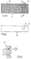
- the shaft 10 has a thread 14, for example a conventional metric thread, which is also fully profiled in the shaft.
- the free end of the shaft 10 has a conical section 16.
- the area surrounded by the dash-dotted circle 2 is shown in perspective in FIG. 2. It can be seen that the flanks 18 of the thread 14 are deformed in a peripheral region, as can be seen at 20.
- the deformation 20 consists in an axial offset Pv of the flanks 18 by one certain amount, where Pv can be 15 to 50% of the pitch P of the thread 14. Between the transition sections 22, the axially offset sections 20 run like the flanks of the rest of the thread 14, only shifted by the mentioned axial offset.
- the extent of the sections 20 in the circumferential direction of the screw can be 1/4 to 1/5 of the circumference.
- the axially offset sections 20 can extend over the entire thread, as indicated in FIG. 1.
- a securing area which consists of a series of axially offset flank sections, are shown.
- all axially offset flank sections 20 are of the same length, and the securing area extends parallel to the screw axis.
- the row of flank sections also extends axially parallel, but the length gradually increases in the direction of the screw head 12 (wedge shape).
- a rolling jaw 30 is shown with which the thread 14 can be formed.
- the rolling jaw 30 is manufactured in the usual way. However, it has an insert 32 which can have a slightly wedge-shaped cross-section (FIG. 4) and which is received in a correspondingly shaped recess 34.
- the shaped thread of the rolling jaw 30 is produced in the usual way, the thread being simultaneously shaped in the insert 32 in the same way.
- the stake is then shifted by the amount Pv and preferably only fixed at one end (not shown).
- the thread 14 is then rolled, so that the thread 14 in the A design results in the rolling jaw 30.
- 3 shows the state of the rolling jaw 30 after the insert 32 has been displaced. This also results from the sectional view according to FIG. 5.
Abstract
Description
Schrauben, die in ein vorhandenes Muttergewinde eingeschraubt werden, können sich lösen, insbesondere wenn Erschütterungen auf die Schraubverbindung wirken. Dies ist z.B. der Fall bei Maschinenschrauben, die auf Erschütterungen erleidenden Teilen angeordnet sind, beispielsweise bei Automobilen. Das ungewollte Selbstlösen wird durch eine Relativbewegung verursacht, da das Gewinde normalerweise nicht absolut spielfrei hergestellt werden kann bzw. darf. Ein ungewolltes Lösen einer Schraube ist nicht nur lästig, sondern häufig auch mit Gefahren verbunden. Es bestehen daher viele konstruktive Vorschläge, ein ungewolltes Losdrehen von Schrauben zu verhindern. Eine Gruppe von Sicherungsmitteln sieht Elemente am Schraubenkopf oder unterhalb des Schraubenkopfes im oberen Bereich des Schaftes vor, welche eine Hemmung zwischen Kopf und/oder Schaft einerseits und dem Werkstück andererseits erzeugen. Abgesehen davon, daß diese Sicherungsmittel häufig unzureichend sind, erfordern sie einen zusätzlichen Fertigungsaufwand. Eine andere Gruppe bezieht sich auf die Formgebung des Gewindes selbst, durch welche ein fester Sitz der Schraube im Muttergewinde erreicht werden soll. Derartige konstruktive Maßnahmen an einem Schraubengewinde erfordern jedoch zumeist einen hohen Herstellungaufwand.Screws that are screwed into an existing nut thread can loosen, especially if vibrations act on the screw connection. This is the case, for example, with machine screws which are arranged on parts suffering from vibrations, for example in automobiles. The unwanted self-loosening is caused by a relative movement, since the thread cannot normally be made without play. Unintentional loosening of a screw is not only annoying, it is also often associated with dangers. There are therefore many constructive proposals to prevent screws from being loosened unintentionally. A group of securing means provides elements on the screw head or below the screw head in the upper region of the shaft, which create an inhibition between the head and / or shaft on the one hand and the workpiece on the other. In addition to the fact that these securing means are often inadequate, they require additional manufacturing effort. Another group relates to the shape of the thread itself, through which a tight fit of the screw in the nut thread is to be achieved. Such design measures on a screw thread, however, usually require a high manufacturing effort.
Der Erfindung liegt die Aufgabe zugrunde, eine Schraube mit selbstsicherndem Gewinde zu schaffen, die einfach herstellbar ist und eine Relativbewegung in einer Schraubverbindung sicher verhindert.The invention has for its object to provide a screw with a self-locking thread that is easy to manufacture and reliably prevents relative movement in a screw connection.
Diese Aufgabe wird durch die Merkmale des Kennzeichnungsteils des Patentanspruches 1 gelöst.This object is achieved by the features of the characterizing part of patent claim 1.
Die Erfindung gehört zur oben zuletzt erwähnten Kategorie. Das Gewinde weist in mindestens einer Gewindeflanke des mit einem Muttergewinde in Eingriff befindlichen Bereiches einen über eine begrenzte Umfangslänge sich erstreckenden axial versetzten Abschnitt auf. Vorzugsweise sind mehrere Gewindeflanken mit axial versetzten Abschnitten versehen, die gegenseitig in Umfangsrichtung versetzt sein können. Vorzugsweise sind die axial versetzten Flankenabschnitte mehrerer Windungen in einer Reihe angeordnet, vorzugsweise parallel zur Schraubenachse. Vorzugsweise erstreckt sich der die axial versetzten Flankenabschnitte aufweisende Sicherheitsbereich über die gesamte Schraubenlänge. Bei in Reihe angeordneten axial versetzten Flankenabschnitten können diese über den Umfang die gleiche Umfangslänge aufweisen. Vorzugsweise kann die Umfangslänge der axial versetzten Flankenabschnitte von der Schraubenspitze zum Schraubenkopf allmählich zunehmen.The invention belongs to the last-mentioned category. In at least one thread flank of the area in engagement with a nut thread, the thread extends over a limited circumferential length axially offset section. Preferably, several thread flanks are provided with axially offset sections which can be offset from one another in the circumferential direction. The axially offset flank sections of a plurality of turns are preferably arranged in a row, preferably parallel to the screw axis. The safety region which has the axially offset flank sections preferably extends over the entire screw length. In the case of axially offset flank sections arranged in a row, these can have the same circumferential length over the circumference. Preferably, the circumferential length of the axially offset flank sections can gradually increase from the screw tip to the screw head.
Beim Einsatz der erfindungsgemäßen Schraube in ein vorhandenes Muttergewinde wird durch den Versatz der Gewindeflanke am Schraubengewinde Umformarbeit geleistet, so daß ein spielfreies Gewinde erzeugt und somit eine Relativbewegung in der Schraubverbindung verhindert wird. Ist eine Relativbewegung nicht mehr möglich, kann es auch nicht mehr zum ungewollten Lösen der Verbindung kommen.When the screw according to the invention is used in an existing nut thread, the offset of the thread flank on the screw thread means that forming work is carried out, so that a thread free of play is generated and thus a relative movement in the screw connection is prevented. If a relative movement is no longer possible, the connection can no longer be unintentionally released.
Nach einer weiteren Ausgestaltung der Erfindung kann sich der axial versetzte Flankenabschnitt über 1/4 bis 1/5 des Schraubenumfanges erstrecken. Grundsätzlich ist es auch möglich, pro Windung mehr als einen axial versetzten Flankenabschnitt vorzusehen, z.B. zwei oder drei, die im Umfangsabstand angeordnet sind und dementsprechend eine geringere Umfangslänge haben als z.B. ein einziger axial versetzter Flankenabschnitt. Ein derartiges Gewinde läßt sich jedoch schwerer herstellen.According to a further embodiment of the invention, the axially offset flank section can be 1/4 to 1/5 of the Extend the circumference of the screw. In principle, it is also possible to provide more than one axially offset flank section per turn, for example two or three, which are arranged at a circumferential distance and accordingly have a shorter circumferential length than, for example, a single axially offset flank section. However, such a thread is more difficult to manufacture.
Der axiale Versatz der Gewindeflanke muß ein Minimum aufweisen, damit die angestrebte Verformungsarbeit erreicht wird. Andererseits darf er nicht zu groß sein, da sonst der Kraftaufwand zum Eindrehen der Schraube in das Muttergewinde zu hoch wird. Ein zu großer Versatz erhöht das Schraubmoment unzulässig, während das Vorspannmoment verkleinert wird. Nach einer Ausgestaltung der Erfindung beträgt das Versatzmaß 15 bis 50 % der Gewindesteigung. Ein Versatzmaß über 50 % ist aus den erwähnten Gründen unzweckmäßig.The axial offset of the thread flank must have a minimum so that the desired deformation work is achieved. On the other hand, it must not be too large, since otherwise the effort required to screw the screw into the nut thread will be too great. If the offset is too large, the tightening torque is impermissible, while the preload torque is reduced. According to one embodiment of the invention, the offset dimension is 15 to 50% of the thread pitch. An offset of more than 50% is inappropriate for the reasons mentioned.
Die erfindungsgemäße Schraube weist zweckmäßigerweise ein im übrigen voll profiliertes Gewinde auf, wobei der die versetzten Flanken aufweisende Sicherungsbereich eine wesentliche Änderung des Gewindeprofils nicht bewirkt.The screw according to the invention expediently has an otherwise fully profiled thread, the securing region having the offset flanks not causing a substantial change in the thread profile.
Die erfindungsgemäße Schraube kann mit Hilfe herkömmlicher Walzbacken hergestellt werden. Ein erfindungsgemäßes Verfahren sieht vor, daß zunächst eine Gewindewalzbacke mit dem Formprofil für das Schraubgewinde ohne versetzte Flankenabschnitte hergestellt wird, wobei anschließend ein von der Größe eines die versetzten Abschnitte aufweisenden Sicherungsabschnitts der Walzbacke annähernd senkrecht zu den Gewindeflanken um das Versatzmaß relativ verschoben und anschließend das Schraubgewinde geformt wird. Mit dem versetzten Abschnitt der Walzbacke wird beim Gewindewalzen der Sicherungsbereich geformt. Die Walzbacke zur Durchführung des Verfahrens weist nach einer weiteren Ausgestaltung der Erfindung mindestens einen Einsatz auf, der passend von einer Ausnehmung der Walzbacke aufnehmbar ist und der annähernd senkrecht zu den Gewindeflanken verschiebbar ist. Es können Mittel vorgesehen werden zur mindestens einendigen Festlegung des Einsates nach dem Versetzen in der Walzbacke vor dem Formen des Schraubgewindes.The screw according to the invention can be used with conventional Rolling jaws are manufactured. A method according to the invention provides that first a thread rolling jaw with the shaped profile for the screw thread is produced without offset flank sections, with a locking section of the rolling jaw having the size of the offset portions being approximately displaced by the offset dimension approximately perpendicular to the thread flanks and then the screw thread is formed. With the offset section of the rolling jaw, the securing area is formed during thread rolling. According to a further embodiment of the invention, the rolling jaw for carrying out the method has at least one insert which can be accommodated by a recess in the rolling jaw and which can be displaced approximately perpendicular to the thread flanks. Means can be provided for at least one-end fixing of the insert after being moved in the rolling jaw before the screw thread is formed.
Die Erfindung wird nachfolgend anhand von Zeichnungen näher erläutert.
- Fig. 1
- zeigt eine Schraube in einem Sicherungsbereich nach der Erfindung in Seitenansicht.
- Fig. 2
- zeigt perspektivisch einen Teil des Schraubgewindes der Schraube nach Fig. 1 in einem Teil des Sicherungsbereiches.
- Fig. 3
- zeigt eine Draufsicht auf eine abgewickelte Gewindewalzbacke zur Herstellung des Gewindes nach Fig. 2.
- Fig. 4
- zeigt eine Seitenansicht der abgewickelten Walzbacke nach Fig. 3 in Richtung Pfeil 4.
- Fig. 5
- zeigt einen Schnitt durch die abgewickelte Walzbacke nach Fig. 3 entlang der Linie V-V.
- Fig. 1
- shows a screw in a securing area according to the invention in side view.
- Fig. 2
- shows in perspective a part of the screw thread of the screw of FIG. 1 in a part of the securing area.
- Fig. 3
- shows a top view of a developed thread rolling jaw for producing the thread according to FIG. 2.
- Fig. 4
- 3 shows a side view of the unwound roll jaw according to FIG. 3 in the direction of arrow 4.
- Fig. 5
- shows a section through the unwound roll jaw of FIG. 3 along the line VV.
Eine Schraube nach Fig. 1 weist einen Schaft 10 und einen Sechskantkopf 12 auf. Der Schaft 10 besitzt ein Gewinde 14, beispielsweise ein übliches metrisches Gewinde, das voll profiliert auch im Schaft geformt ist. Das freie Ende des Schaftes 10 besitzt einen konischen Abschnitt 16. Der mit dem strichpunktierten Kreis 2 umrandete Bereich ist in Fig. 2 perspektivisch dargestellt. Man erkennt, daß die Flanken 18 des Gewindes 14 in einem Umfangsbereich verformt sind, wie bei 20 zu erkennen. Die Verformung 20 besteht in einem axialen Versatz Pv der Flanken 18 um einen bestimmten Betrag, wobei Pv 15 bis 50 % der Steigung P des Gewindes 14 betragen kann. Zwischen den Übergangsabschnitten 22 verlaufen die axial versetzten Abschnitte 20 wie die Flanken des übrigen Gewindes 14, nur um den erwähnten axialen Versatz verschoben. Die Erstreckung der Abschnitte 20 in Umfangsrichtung der Schraube kann 1/4 bis 1/5 des Umfanges betragen. Die axial versetzten Abschnitte 20 können sich über das gesamte Gewinde erstrecken, wie in Fig. 1 angedeutet. In Fig. 1 sind zwei Möglichkeiten für die Ausbildung eines Sicherungsbereiches, der aus einer Reihe axial versetzter Flankenabschnitte besteht, gezeigt. Bei der ersten Ausführung A sind alle axial versetzten Flankenabschnitte 20 von gleicher Länge, und der Sicherungsbereich erstreckt sich parallel zur Schraubenachse. Bei der Ausführung B erstreckt sich die Reihe der Flankenabschnitte ebenfalls achsparallel, die Länge wird jedoch in Richtung Schraubenkopf 12 allmählich größer (Keilform).1 has a
Bei einem Einschrauben einer Schraube 10 in Schraubrichtung 24 (Fig. 2) leistet das Muttergewinde Verformungsarbeit und verformt die axial versetzten Abschnitte 20 zurück, so daß sich ein spielfreier Sitz ergibt. Der Versatz der Steigungen ergibt Pv, das nicht zu groß sein darf, da sonst das Einschraubmoment zu hoch wird.When a
In den Fig. 3 bis 5 ist eine Walzbacke 30 dargestellt, mit der das Gewinde 14 geformt werden kann. Die Walzbacke 30 ist in üblicher Weise hergestellt. Sie weist indessen einen Einsatz 32 auf, der leicht keilförmig im Querschnitt geformt sein kann (Fig. 4), der in einer entsprechend geformten Ausnehmung 34 aufgenommen ist. Das Formgewinde der Walzbacke 30 wird in üblicher Weise hergestellt, wobei das Gewinde in gleicher Weise im Einsatz 32 gleichzeitig mitgeformt wird. Anschließend wird der Einsatz um den Betrag Pv verschoben und vorzugsweise nur an einem Ende festgelegt (nicht gezeigt). Danach erfolgt das Walzen des Gewindes 14, so daß sich bei der Walzbacke 30 das Gewinde 14 in der Ausführung A ergibt. In Fig. 3 ist der Zustand der Walzbacke 30 nach der Verschiebung des Einsatzes 32 dargestellt. Dies ergibt sich auch aus dem Schnittbild nach Fig. 5.3 to 5, a rolling
Claims (9)
Applications Claiming Priority (2)
| Application Number | Priority Date | Filing Date | Title |
|---|---|---|---|
| DE19904039402 DE4039402A1 (en) | 1990-12-10 | 1990-12-10 | SCREW WITH SELF-LOCKING THREAD |
| DE4039402 | 1990-12-10 |
Publications (1)
| Publication Number | Publication Date |
|---|---|
| EP0490194A1 true EP0490194A1 (en) | 1992-06-17 |
Family
ID=6419997
Family Applications (1)
| Application Number | Title | Priority Date | Filing Date |
|---|---|---|---|
| EP91120567A Withdrawn EP0490194A1 (en) | 1990-12-10 | 1991-11-29 | Screw with selfblocking thread |
Country Status (2)
| Country | Link |
|---|---|
| EP (1) | EP0490194A1 (en) |
| DE (1) | DE4039402A1 (en) |
Cited By (1)
| Publication number | Priority date | Publication date | Assignee | Title |
|---|---|---|---|---|
| CN107702666A (en) * | 2017-08-30 | 2018-02-16 | 北京航天控制仪器研究所 | A kind of screw thread and the measuring method of reference axis axiality |
Families Citing this family (3)
| Publication number | Priority date | Publication date | Assignee | Title |
|---|---|---|---|---|
| DE102008027297A1 (en) | 2008-06-06 | 2009-12-10 | Pee-Wee Kaltwalz- Und Rohrbearbeitungsmaschinen Gmbh | Connecting element for a screw connection and such a screw connection |
| DE102010037757A1 (en) | 2010-09-24 | 2012-03-29 | Pee-Wee Kaltwalz- Und Rohrbearbeitungsmaschinen Gmbh | Screw thread for e.g. screw bolt and nut, has edges with protrusion on both sides of groove, where thread exhibits smaller thread depth in region of clamping portion if pitch is smaller or equivalent to preset value than outside of portion |
| DE102014214788A1 (en) * | 2014-07-28 | 2016-01-28 | Robert Bosch Gmbh | High-pressure connection device, method and tool for producing a high-pressure connection device and fuel injection valve with a high-pressure connection device |
Citations (5)
| Publication number | Priority date | Publication date | Assignee | Title |
|---|---|---|---|---|
| CH471978A (en) * | 1967-04-14 | 1969-04-30 | Burdsall & Ward Co | Locking screw |
| US3452375A (en) * | 1967-05-10 | 1969-07-01 | Eric G Gabbey | Process for producing self-locking screw threads |
| US3481380A (en) * | 1967-05-18 | 1969-12-02 | Lamson & Sessions Co | Thread forming fastener |
| LU67373A1 (en) * | 1972-04-09 | 1973-06-18 | ||
| DE3804291A1 (en) * | 1988-02-12 | 1989-08-24 | Bergner Richard Gmbh Co | Clamping screw |
-
1990
- 1990-12-10 DE DE19904039402 patent/DE4039402A1/en not_active Withdrawn
-
1991
- 1991-11-29 EP EP91120567A patent/EP0490194A1/en not_active Withdrawn
Patent Citations (5)
| Publication number | Priority date | Publication date | Assignee | Title |
|---|---|---|---|---|
| CH471978A (en) * | 1967-04-14 | 1969-04-30 | Burdsall & Ward Co | Locking screw |
| US3452375A (en) * | 1967-05-10 | 1969-07-01 | Eric G Gabbey | Process for producing self-locking screw threads |
| US3481380A (en) * | 1967-05-18 | 1969-12-02 | Lamson & Sessions Co | Thread forming fastener |
| LU67373A1 (en) * | 1972-04-09 | 1973-06-18 | ||
| DE3804291A1 (en) * | 1988-02-12 | 1989-08-24 | Bergner Richard Gmbh Co | Clamping screw |
Cited By (1)
| Publication number | Priority date | Publication date | Assignee | Title |
|---|---|---|---|---|
| CN107702666A (en) * | 2017-08-30 | 2018-02-16 | 北京航天控制仪器研究所 | A kind of screw thread and the measuring method of reference axis axiality |
Also Published As
| Publication number | Publication date |
|---|---|
| DE4039402A1 (en) | 1992-06-11 |
Similar Documents
| Publication | Publication Date | Title |
|---|---|---|
| DE3610392C2 (en) | Screw for contaminated tapped holes | |
| DE19900791B4 (en) | Connecting element for two machine or components, in particular fitting expansion screw, fitting threaded bolt or the like. | |
| DE2538139C2 (en) | screw | |
| DE2907360C2 (en) | Thread forming screw and blank for their manufacture | |
| DE2617136A1 (en) | THREADED COMPONENT, IN PARTICULAR SCREW | |
| DE4333791A1 (en) | Self-tapping screw | |
| DE1400883B1 (en) | Chipless thread-producing screw | |
| DE19902461A1 (en) | Nut with T-shaped cross-section for use inside hollow shafts made of e.g. plastic wood | |
| WO2003011508A2 (en) | Thread former or tap | |
| DE1750617A1 (en) | Fasteners and process for their manufacture | |
| DE2461546A1 (en) | THREAD FORMING SCREW | |
| DE2649766C2 (en) | ||
| DE3703031A1 (en) | FASTENING DEVICE WITH A U-NUT | |
| EP0408492B1 (en) | Screw nut | |
| DE102007036733A1 (en) | Threaded bolt and method for its production | |
| DE3803149A1 (en) | SCREW | |
| DE2521684A1 (en) | VIBRATION-PROOF FIXING ELEMENT | |
| EP2224143A1 (en) | Nut, screw connection, profile connection and method for producing a nut | |
| DE2365132C3 (en) | ||
| EP0292734B1 (en) | Thread forming screw | |
| DE102005050919A1 (en) | Locking nut or bolt has integral locking section with thread of different pitch and profile to non-locking sections, increasing force required to release it | |
| DE2625997A1 (en) | SAFETY THREAD | |
| EP0490194A1 (en) | Screw with selfblocking thread | |
| DE102009005336A1 (en) | Screw element, screw connection and method for producing a screw element | |
| EP3519708B1 (en) | Internally threaded locking element, threaded connection and production method and tool |
Legal Events
| Date | Code | Title | Description |
|---|---|---|---|
| PUAI | Public reference made under article 153(3) epc to a published international application that has entered the european phase |
Free format text: ORIGINAL CODE: 0009012 |
|
| AK | Designated contracting states |
Kind code of ref document: A1 Designated state(s): DE ES FR GB NL |
|
| 17P | Request for examination filed |
Effective date: 19920921 |
|
| 17Q | First examination report despatched |
Effective date: 19930929 |
|
| STAA | Information on the status of an ep patent application or granted ep patent |
Free format text: STATUS: THE APPLICATION IS DEEMED TO BE WITHDRAWN |
|
| 18D | Application deemed to be withdrawn |
Effective date: 19940210 |