EP0489847B1 - Interferometer utilizing superfluorescent optical source - Google Patents
Interferometer utilizing superfluorescent optical source Download PDFInfo
- Publication number
- EP0489847B1 EP0489847B1 EP90913928A EP90913928A EP0489847B1 EP 0489847 B1 EP0489847 B1 EP 0489847B1 EP 90913928 A EP90913928 A EP 90913928A EP 90913928 A EP90913928 A EP 90913928A EP 0489847 B1 EP0489847 B1 EP 0489847B1
- Authority
- EP
- European Patent Office
- Prior art keywords
- light
- optical
- optical fiber
- interferometer
- waveguide
- Prior art date
- Legal status (The legal status is an assumption and is not a legal conclusion. Google has not performed a legal analysis and makes no representation as to the accuracy of the status listed.)
- Expired - Lifetime
Links
- 230000003287 optical effect Effects 0.000 title claims description 85
- 239000013307 optical fiber Substances 0.000 claims abstract description 164
- 238000005253 cladding Methods 0.000 claims description 35
- 230000001902 propagating effect Effects 0.000 claims description 27
- 239000000463 material Substances 0.000 claims description 19
- 229910052779 Neodymium Inorganic materials 0.000 claims description 11
- QEFYFXOXNSNQGX-UHFFFAOYSA-N neodymium atom Chemical compound [Nd] QEFYFXOXNSNQGX-UHFFFAOYSA-N 0.000 claims description 11
- 238000000034 method Methods 0.000 claims description 10
- 230000005855 radiation Effects 0.000 claims description 10
- 230000008878 coupling Effects 0.000 claims description 4
- 238000010168 coupling process Methods 0.000 claims description 4
- 238000005859 coupling reaction Methods 0.000 claims description 4
- 230000010287 polarization Effects 0.000 claims description 3
- 238000005086 pumping Methods 0.000 claims description 2
- 230000004044 response Effects 0.000 claims description 2
- 239000000835 fiber Substances 0.000 abstract description 47
- 230000010355 oscillation Effects 0.000 abstract description 8
- 230000002269 spontaneous effect Effects 0.000 description 7
- UIAFKZKHHVMJGS-UHFFFAOYSA-N 2,4-dihydroxybenzoic acid Chemical compound OC(=O)C1=CC=C(O)C=C1O UIAFKZKHHVMJGS-UHFFFAOYSA-N 0.000 description 4
- 229910052691 Erbium Inorganic materials 0.000 description 4
- 230000000694 effects Effects 0.000 description 4
- UYAHIZSMUZPPFV-UHFFFAOYSA-N erbium Chemical compound [Er] UYAHIZSMUZPPFV-UHFFFAOYSA-N 0.000 description 4
- 230000003595 spectral effect Effects 0.000 description 3
- 230000007704 transition Effects 0.000 description 3
- VYPSYNLAJGMNEJ-UHFFFAOYSA-N Silicium dioxide Chemical compound O=[Si]=O VYPSYNLAJGMNEJ-UHFFFAOYSA-N 0.000 description 2
- 238000010521 absorption reaction Methods 0.000 description 2
- 239000011248 coating agent Substances 0.000 description 2
- 238000000576 coating method Methods 0.000 description 2
- 230000007423 decrease Effects 0.000 description 2
- 230000004048 modification Effects 0.000 description 2
- 238000012986 modification Methods 0.000 description 2
- 229920000642 polymer Polymers 0.000 description 2
- 230000000644 propagated effect Effects 0.000 description 2
- 239000011149 active material Substances 0.000 description 1
- PNEYBMLMFCGWSK-UHFFFAOYSA-N aluminium oxide Inorganic materials [O-2].[O-2].[O-2].[Al+3].[Al+3] PNEYBMLMFCGWSK-UHFFFAOYSA-N 0.000 description 1
- 230000003321 amplification Effects 0.000 description 1
- 230000008901 benefit Effects 0.000 description 1
- 230000015572 biosynthetic process Effects 0.000 description 1
- 230000008859 change Effects 0.000 description 1
- 230000001427 coherent effect Effects 0.000 description 1
- 229910052593 corundum Inorganic materials 0.000 description 1
- 230000005284 excitation Effects 0.000 description 1
- 230000005283 ground state Effects 0.000 description 1
- 239000000146 host glass Substances 0.000 description 1
- 230000003993 interaction Effects 0.000 description 1
- 230000002452 interceptive effect Effects 0.000 description 1
- PLDDOISOJJCEMH-UHFFFAOYSA-N neodymium oxide Inorganic materials [O-2].[O-2].[O-2].[Nd+3].[Nd+3] PLDDOISOJJCEMH-UHFFFAOYSA-N 0.000 description 1
- 238000003199 nucleic acid amplification method Methods 0.000 description 1
- 230000008569 process Effects 0.000 description 1
- 238000001228 spectrum Methods 0.000 description 1
- 230000002123 temporal effect Effects 0.000 description 1
- 229910001845 yogo sapphire Inorganic materials 0.000 description 1
Images


Classifications
-
- G—PHYSICS
- G01—MEASURING; TESTING
- G01C—MEASURING DISTANCES, LEVELS OR BEARINGS; SURVEYING; NAVIGATION; GYROSCOPIC INSTRUMENTS; PHOTOGRAMMETRY OR VIDEOGRAMMETRY
- G01C19/00—Gyroscopes; Turn-sensitive devices using vibrating masses; Turn-sensitive devices without moving masses; Measuring angular rate using gyroscopic effects
- G01C19/58—Turn-sensitive devices without moving masses
- G01C19/64—Gyrometers using the Sagnac effect, i.e. rotation-induced shifts between counter-rotating electromagnetic beams
- G01C19/72—Gyrometers using the Sagnac effect, i.e. rotation-induced shifts between counter-rotating electromagnetic beams with counter-rotating light beams in a passive ring, e.g. fibre laser gyrometers
- G01C19/721—Details
-
- G—PHYSICS
- G01—MEASURING; TESTING
- G01P—MEASURING LINEAR OR ANGULAR SPEED, ACCELERATION, DECELERATION, OR SHOCK; INDICATING PRESENCE, ABSENCE, OR DIRECTION, OF MOVEMENT
- G01P3/00—Measuring linear or angular speed; Measuring differences of linear or angular speeds
- G01P3/36—Devices characterised by the use of optical means, e.g. using infrared, visible, or ultraviolet light
Definitions
- the present invention is in the field of optical interferometers and components, and, in particular, is in the field of broadband light sources for interferometers, rotation sensors, and the like.
- a Sagnac interferometer comprises an optical loop, typically of optical fiber, that is used to sense rotation of an object onto which the loop is mounted.
- interferometers operate by dividing the optical energy from a light source into two substantially equal beams of light and causing the two beams of light to propagate around the loop in opposite directions. The two beams of light are combined after passing through the loop and the changes in intensity of the combined light caused by interference of the two beams is detected.
- rotation of the object and thus of the loop of fiber causes changes in the relative phase between light propagating in the two directions which in turn causes the detected intensity to change.
- the rotation rate of the loop can be determined from the detected changes in the intensity. See, for example, U.S. Patent Nos. 4,410,275; 4,529,312; 4,637,722; 4,671,658; 4,687,330 and 4,836,676.
- a broadband light source to provide the light introduced into the loop of optical fiber. See, for example, U.S. Patent No. 4,637,025 wherein a super radiant light source is described.
- the light source in U.S. Patent No. 4,637,025 operates by introducing a pump signal into a single-mode optical fiber having a core doped with an active fluorescent material such as neodymium or other rare earths.
- the pump light has a sufficient intensity to cause amplification of spontaneous emission of photons by the fluorescent material.
- pump light is input into the optical fiber via a lens.
- the pump light is introduced via a dichroic lens that is transparent to the pump light and highly reflective of emitted light.
- the pump light is absorbed by the fluorescent material and excites the electrons therein to higher energy states resulting in the emission light when the electrons transition to lower states. Because of the random manner in which the spontaneous emissions occur, the amplified emitted light is effectively spontaneous fluorescence and temporally incoherent.
- the two embodiments in U.S. Patent No. 4,637,025 generate light that is emitted in all directions in the core of the fiber. A portion of the light generated in the core propagates directly out the output end of the fiber. A second portion of the light propagates toward the input end of the fiber. In the first embodiment, the light reaches the input end of the fiber. Although the input end does not have a reflector, as in the second embodiment, surfaces in the optical path cause a portion of the generated light to be reflected back into the fiber. In the second embodiment, the dichroic reflector is included to specifically reflect the generated light that propagates toward the input end portion back toward the output end portion.
- the present invention comprises an interferometer having a light source and an optical loop.
- the light source comprises an optical waveguide formed of a material which emits a broadband optical signal in response to pumping with pump radiation.
- the light source introduces the emitted optical signal to the optical loop along a connecting optical path extending between the optical loop and the light source.
- the loop returns at least a portion of light comprising the emitted optical signal back to the light source along the connecting optical path to provide a returning broadband optical signal.
- the light source is non-reflective for the returning optical signal, to prevent the returning optical signal from being reflected back to the loop. By preventing such reflection, the interferometer avoids resonance between the source and the loop, and prevents substantial narrowing of the spectral line width.
- the light source additionally comprises a source of pump light coupled to optically pump the light-emitting material such that the pump light propagates in the waveguide in a direction opposite to that of the emitted optical signal.
- the waveguide comprises an optical fiber having a core surrounded by a cladding, and the pump light source couples the pump light into the cladding.
- the optical fiber has a first numerical aperture corresponding to a first acceptance region, and the cladding has a second numerical aperture corresponding to a second acceptance region.
- the acceptance regions define an aperture window therebetween, and the pump source introduces the pump light into the aperture window at one end of the fiber.
- the core of the optical fiber is circular and single mode, while the cladding is rectangular and multi-mode.
- the fiber is doped with neodymium or other light-emitting material.
- the returning optical signal propagates through the waveguide and exits the waveguide at an end thereof.
- a photodetector is positioned at such end to detect the returning optical signal, and is arranged to prevent light incident thereon from being reflected back into the loop.
- the optical loop comprises an optical waveguide having two polarization modes, and the emitted optical signal has a coherence time which is significantly less than the propagation time difference between the modes after traversing the length of the loop.
- the invention also encompasses a method of operating an interferometer having a light source and an optical sensing loop.
- pump radiation is input to an optical waveguide to pump the optical waveguide to emit broadband light.
- Emitted light from the light source propagates towards the optical sensing loop, and light from the optical sensing loop is returned towards the light source without returning to the loop to prevent optical resonance of the emitted light in the interferometer.
- the emitted light is emitted from a first end of the waveguide and the pump radiation is coupled to the waveguide in the form of optical energy at a location between the sensing loop and a second end of the waveguide.
- a further preferred aspect of the method involves passing the emitted light propagating from the loop to the source through the waveguide to provide amplified light and detecting the amplified light.
- Figure 1 is a pictorial representation of a conventional broadband light source.
- Figure 2 is a pictorial representation of a conventional Sagnac interferometer.
- Figure 3 is a pictorial representation of a conventional Sagnac interferometer and a broadband light source in accordance with one aspect of the present invention.
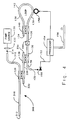
- Figure 4 is a pictorial representation of a conventional Sagnac interferometer and a broadband light source in accordance with a second aspect of the present invention.
- FIG. 5 is a pictorial representation of a conventional Sagnac interferometer and a broadband light source in accordance with an additional aspect of the present invention in which the broadband light source comprises a double-clad neodymium-doped optical fiber.
- Figure 6 is a cross-sectional view of the double-clad neodymium-doped optical fiber taken along the lines 6-6 in Figure 5.
- Figure 7 is cross-sectional representation of the juxtaposition of the double-clad neodymium-doped optical fiber with the multimode optical fiber of Figure 5.
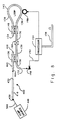
- Figure 8 is a pictorial representation of a conventional Sagnac interferometer and the broadband light source in accordance with the present invention, illustrating an alternative placement of the pump source with respect to the double-clad neodymium doped optical fiber.
- Figure 9 is a pictorial representation of a conventional Sagnac interferometer and the broadband light source in accordance with the present invention, illustrating a further alternative placement of the pump source with respect to the double-clad neodymium doped optical fiber.
- Figure 10 is a pictorial representation of a conventional Sagnac interferometer in combination with a further embodiment of a broadband light source in accordance with the present invention, wherein the pump light is coupled to a doped optical fiber via a dichroic mirror.
- Figure 11 is a pictorial representation of the Sagnac interferometer and the broadband light source of Figure 10, wherein the photodetector is positioned to receive amplified light from the doped optical fiber.
- Figure 12 is a pictorial representation of the Sagnac interferometer and the broadband light source of Figure 3, wherein the photodetector is positioned to receive amplified light from the doped optical fiber.
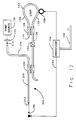
- Figure 13 is a pictorial representation of the Sagnac interferometer and the broadband light source of Figure 9, wherein the photodetector is positioned to receive amplified light from the doped optical fiber.
- Figure 1 illustrates an exemplary broadband light source 100.
- the light source 100 includes a waveguide comprising an optical fiber 110 having a first end 112 and a second end 114.
- the optical fiber 110 is a fluorescent optical fiber. That is, when the optical fiber 110 is pumped with optical energy within specified ranges of optical wavelengths (referred to as the absorption bands of the optical fiber), the optical fiber 110 generates output light having a wavelength responsive to the wavelength of the pump optical energy.
- the optical fiber 110 comprises a core of a host glass that is doped with an active fluorescent material such as neodymium which absorbs light having wavelengths on the order of 0.82 microns, for example.
- the absorbed photons from the pump optical energy excite the electrons in the active material to higher energy electron energy states, and, when the electrons transition to lower energy levels, photons are emitted at characteristic emission bands, or fluorescing wavelengths.
- emission bands are 1.06 microns and 1.35 microns.
- the transitions through the lower energy levels back to the ground state for spontaneous emission occur in a random manner to cause the photon emissions caused by the pump light to be amplified spontaneous fluorescence, thus causing the emitted output light to be temporally incoherent.
- the broadband light source 100 further includes a pump light source 120 which may be, for example, a laser diode, or the like, that provides an optical pump signal having a wavelength within one of the absorption bands of the fluorescent optical fiber 110, for example, 0.82 microns.
- the pump light provided by the pump light source 120 is introduced into the first end 112 of the optical fiber 110 via a lens 122, or the like, so that the pump light propagates in the fluorescent material in the core of the optical fiber 110.
- the intensity of the pump light provided by the pump light source 120 is selected to be sufficiently great to cause a population inversion of the electrons in the fluorescent material, thereby supporting amplified spontaneous emission of light from the fluorescent material.
- the length of the fluorescent optical fiber 110 is selected to be sufficiently long so that substantially all the pump optical energy is absorbed by the fluorescent material and little, if any, pump optical energy is emitted from the second end 114 of the optical fiber 110.
- the emitted light energy has a high radiant intensity relative to the light produced by a so-called super radiant light-emitting diode (LED).
- the emitted light has a wavelength distribution that is broader than the characteristic spectral line output of a laser diode, has a low temporal coherence, and has a principal wavelength that is generally temperature independent.
- the emitted light is generated in all directions within the fluorescent material in the core of the fluorescent optical fiber 110.
- the portion of the light initially propagating in the general direction of the second end 114 (referred to herein as the forward propagating light) will be emitted therefrom as a broadband output signal.
- Figure 2 illustrates a conventional Sagnac interferometer 102 having a light source 123 (typically a superluminescent diode) coupled to an optical fiber 125.
- a light source 123 typically a superluminescent diode
- Light from the source 123 is introduced into the Sagnac interferometer 102 by, for example, forming the optical fiber 125 into one-half of a first directional coupler 126, which is preferably constructed in accordance with U.S. Patent No. 4,536,058, or the like.
- the second half of the first directional coupler is formed on an optical fiber 130 which has a first end 132 and a second end 134.
- the first directional coupler 126 is preferably constructed to couple approximately 50 percent of the light from the fluorescent optical fiber 110 to the optical fiber 130 in the Sagnac interferometer 102.
- the Sagnac interferometer 102 further comprises a second directional coupler 140 that forms a portion of the optical fiber 130 into a loop 142 between the two ends 132 and 134.
- the loop 142 operates as the sensing portion of the interferometer 102.
- the second directional coupler 140 is preferably constructed in the same manner as the first directional coupler 126 and is also preferably a 50 percent coupler such that approximately 50 percent of the light coupled to the optical fiber 130 from the light source 123 propagates around the loop 142 in a first direction (clockwise in Figure 2) and approximately 50 percent propagates around the loop 142 in a second opposite direction (counterclockwise in Figure 2).
- the light propagating around the loop 142 is recombined by the second directional coupler 140, and the recombined light signal propagates back toward the first directional coupler 126. Approximately 50 percent of the light is provided as an output signal via the first end 132 of the optical fiber 130 with the other 50 percent being coupled back to the light source 123.
- the output signal from the first end 132 is detected by a detector 150 which provides an electrical output signal on a line 152 that is provided to a processor 154.
- the processor 154 processes the electrical output signal and provides a calculated output signal ⁇ on a bus 156 responsive to the direction and rate at which the loop 142 is rotated.
- the operation of Sagnac interferometers is well-known and will not be discussed in detail herein. One skilled in the art will recognize that additional components are frequently used to improve the operation of such interferometers.
- the Sagnac interferometer 102 of Figure 2 further includes a phase modulator 158 driven by the processor 154 that introduces a phase modulation into the counterpropagating light signals within the loop 142 to enable the electrical output signal to be synchronously demodulated.
- Sagnac interferometer of this type is disclosed in U.S. Patent Nos. 4,671,658 and 4,881,817.
- Other components such as a polarizer 160 positioned on the optical fiber 130 between the first directional coupler 126 and the second directional coupler 140, are also advantageously used in many applications.
- portions of the Sagnac interferometer 102 can be advantageously constructed using integrated optic components or bulk optic components.
- the broadband light source 110 of Figure 1 may be substituted for the light source 123 of the interferometer 102 to supply broadband light thereto. This may be accomplished either by coupling the second end 114 of the fiber 110 to the input end of the fiber 125 or by forming the fiber 110 into one-half of the first directional coupler 126.
- the light generated in the fluorescent optical fiber 110 that propagates toward the first end 112 (referred to herein as the backward propagating light) will be generally emitted from the first end 112 toward the pump source 120.
- the first end 112 will generally be either a smooth flat end or a smooth spherical end (as described in U.S. Patent No.
- the first end 112 will act as a partial reflector of the backward propagating light and will cause the backward propagating light to be reflected back toward the second end 114 of the optical fiber 110.
- the lens and pump source have surfaces which reflect light.
- the reflected light will also be introduced into Sagnac interferometer 102.
- U.S. Patent No. 4,637,025 it was considered desirable to reflect the backward propagating light.
- Figure 2 of that patent an embodiment is disclosed in which a dichroic reflector is formed on the first end 112 so that substantially all the backward propagating emitted light is reflected toward the second end 114.
- the loop 142 provides the same effect as a mirror, and up to 50 percent of the light introduced into the Sagnac interferometer 102 and propagating around the loop 142 can be coupled back to the light source. If the light source of Figure 1 is used in the interferometer of Figure 2, the source will reflect a portion of this light so that it again propagates back towards the interferometer loop. It can be seen that the source of Figure 1 and the loop of Figure 2 act as the two mirrors of a resonant cavity. Thus, resonant lasing can occur to cause the generation of undesirable temporally coherent laser light.
- Figure 3 illustrates a first embodiment of a broadband light source which prevents the resonant lasing from occurring by eliminating the reflection of light at one end of a fluorescent optical fiber.
- This embodiment uses the same basic configuration as the Sagnac interferometer of Figure 2, and includes the optical fiber 130 having its first end 132 and its second end 134.
- the basic operation of the Sagnac interferometer of Figure 3 is substantially as described above.
- a light source 200 comprises a fluorescent optical fiber 210 which advantageously has a neodymium-doped core such as described above, or other rare earth-doped core such as erbium.
- the fluorescent optical fiber has a first end 212 and a second end 214.
- the light source 200 further includes the pump source 120 which is coupled to the second 214 of the fluorescent optical fiber using the lens 122, for example.
- the pump light introduced into the fluorescent optical fiber 210 propagates from the second end 214 back towards the first end 212.
- the Sagnac interferometer is coupled to the light source 200 via a coupler 220 which is formed onto the fluorescent optical fiber 210 proximate to its second end 214 and is formed onto the optical fiber 130 proximate to its first end 132.
- the coupler 220 of Figure 3 is a multiplexing coupler. As described, for example, in U.S. Patent No. 4,556,279, the multiplexing coupler 220 is constructed so that it couples different percentages of light between the two coupler halves in accordance with the wavelength of the light.
- the multiplexing coupler 220 is constructed so that substantially all the light introduced into the optical fiber 230 at the wavelength of the pump signal (e.g., 0.82 microns) is not coupled and remains in the fluorescent optical fiber 210 to cause the fluorescent effect described above.
- the multiplexing coupler 220 causes approximately 50 percent of the fluorescent light generated within the fluorescent optical fiber 210 and propagating in the forward direction toward the second end 214 to be coupled from the fluorescent optical fiber 210 to the optical fiber 130.
- the coupled light propagates in the optical fiber 130 to the directional coupler 140 and thus to the loop 142 of the Sagnac interferometer.
- the loop 142 comprises a waveguide (such as an optical fiber) having two polarization modes which propagate light at different velocities, such that the light traversing the loop in one mode yields a propagation time difference with respect to light traversing the loop in the other mode.
- the propagation time difference is significantly greater than the coherence time of the light input to the loop.
- the first end 212 of the fluorescent optical fiber 210 is specifically formed to preclude reflections at the first end 212.
- a slashed line across the first end 212 indicates that the first end 212 has been cut at an angle (e.g., 15 degrees) so that light propagating to the first end will be non-reflectively emitted from the first end 212. Thus, substantially no light propagating toward the first end 212 will be reflected back toward the second end 214.
- the detector 150 is positioned proximate to the first end 132 of the optical fiber 130 to detect light emitted therefrom.
- a filter 240 is advantageously positioned between the first end 132 and the detector 240. The purpose for the filter 240 will be briefly discussed below.
- the pump light coupled to the fluorescent optical fiber 210 stimulates the emission of broadband light as discussed above in connection with Figure 1.
- the intensity of the pump light is selected to be sufficiently great to cause a population inversion of the electrons in the fluorescent material, thereby supporting amplified spontaneous emission of light from the fluorescent material.
- the length of the fluorescent optical fiber 210 is selected to be sufficiently long so that substantially all the pump optical energy is absorbed by the fluorescent material and little, if any, pump optical energy is emitted from the first end 212 of the optical fiber 210; however, it should be understood that since the first end 212 is non-reflectively terminated, this is not a stringent requirement.
- the re-combined light returning from the Sagnac interferometer returns to the multiplexing coupler 220 where 50 percent of the re-combined light is coupled to the fluorescent optical fiber 210 and propagates to the first end 212 and is non-reflectively emitted therefrom.
- the other 50 percent of the re-combined light remains in the optical fiber 130 and propagates to the first end 132 where it is emitted.
- the emitted light passes through the filter 240 to the detector 150 where it is detected to generate a responsive electrical signal that is processed as discussed above.
- the multiplexing coupler 220 is preferably constructed so that substantially none of the light from the pump source 120 is coupled to the optical fiber 130, the filter 240 is included to filter out any pump light that may be coupled.
- the filter 240 is selected to have optical characteristics such that substantially all the light at the pump light wavelength (e.g., 0.82 microns) is blocked and such that substantially all the light in the emission band (e.g., 1.06 microns) is transmitted through the filter 240 to the detector 150.
- substantially all the light at the pump light wavelength e.g. 0.82 microns
- substantially all the light in the emission band e.g., 1.06 microns
- a portion of the light emitted by the pump source 120 may undesirably couple through the multiplexing coupler 220 to the optical fiber 130. There is a possibility that the pump light could interfere with the operation of the detector 150.
- FIG 4 illustrates an alternative embodiment of the present invention in which the detector 150 is effectively isolated from the pump light.
- the Sagnac interferometer is coupled to a broadband light source 300.
- the broadband light source 300 includes a fluorescent optical fiber 310 having a first end 312 and a second end 314.
- the fluorescent optical fiber 310 has the characteristics discussed above.
- a first multiplexing coupler 320 is formed on the fluorescent optical fiber 310 to couple the fluorescent optical fiber to an optical fiber 330.
- the optical fiber 330 has a first end 332 and a second end 334.
- the pump light source 120 is positioned to input light to the second end 314 of the fluorescent optical fiber 310 via the lens 122, as discussed above.
- the multiplexing coupler 320 is constructed so that substantially none of the pump light is coupled from the fluorescent optical fiber 310 to the optical fiber 330. Thus, substantially all the pump light propagates toward the first end 312 and is absorbed by the fluorescent material in the fluorescent optical fiber 310.
- the first end of the fluorescent optical fiber 310 is non-reflectively terminated (e.g., by cutting it at an angle of, for example, 15 degrees) so that substantially all the pump light and substantially all of the emitted light propagating toward the first end 312 are discharged therefrom.
- the multiplexing coupler 320 is further constructed to provide substantially 100 percent coupling at the emission wavelength (e.g., 1.06 microns) of the fluorescent optical fiber 310 so that the emitted light propagating toward the second end 314 is coupled from the fluorescent optical fiber 310 to the optical fiber 330. Thus, substantially none of the light in the emission band will propagate to the pump source 120.
- the emission wavelength e.g., 1.06 microns
- the first half of the first directional coupler 126 is formed on the optical fiber 330.
- the second half of the first directional coupler is formed on the optical fiber 130.
- the first directional coupler 126 is constructed to couple approximately 50 percent of the light in the optical fiber 330 to the optical fiber 130 in the Sagnac interferometer.
- the 50-percent portion of the light coupled to the optical fiber 130 propagates to the second directional coupler 140 and is thus coupled to the loop 142 of the Sagnac interferometer.
- the re-combined light from the coupler 140 of the Sagnac interferometer propagates back to the first directional coupler 126. Approximately 50 percent of the light remains in the optical fiber 130 and is emitted from the first end 132 to the detector 150. The other 50 percent of the re-combined light is coupled to the optical fiber 330 and propagates back to the multiplexing coupler 320 where it is coupled to the fluorescent optical fiber 310 to propagate to the non-reflective first end 312 and be discharged therefrom. Again, the first end 312 is non-reflectively terminated to prevent the formation of a resonant cavity.
- the detector 150 is positioned proximate to the first end 132 of the optical fiber 130. It can be seen that there is substantially no probability of any of the pump light reaching the detector 150 with the pump source 120 positioned as shown. Thus, there is no need for a filter between the first end 132 and the detector 150.
- Figure 5 illustrates a further embodiment of the present invention.
- the interferometer is constructed substantially as described above.
- the interferometer is connected to a broadband light source 400 via the first directional coupler 126.
- the directional coupler 126 couples the optical fiber 130 to an optical fiber 402 that has a first end 404 and a second end 406.
- the broadband light source 400 is constructed using a double-clad fluorescent optical fiber 410 such as is available from Polaroid Corporation.
- the double-clad optical fiber 400 is shown in more detail in a cross sectional view in Figure 6.
- the double-clad optical fiber 410 includes an inner core 420 comprising silica glass doped with approximately 0.5 percent by weight of Nd2O3 and 3.8 percent by weight of Al2O3.
- the core 420 has a numerical aperture of 0.16.
- the core 420 has a diameter of approximately 4.8 microns and is surrounded by a first cladding 422 having an approximately rectangular shape (e.g., having two substantially parallel sides connected by slightly rounded ends, as shown).
- the first cladding 422 has approximate rectangular dimensions of 110 microns by 45 microns to provide a ratio of first cladding area to core area of approximately 274.
- the first cladding 422 comprises mainly silica (SiO2).
- the first cladding 422 is surrounded by a second cladding 424 which is a first buffer coating.
- the second cladding 424 comprises a soft fluro-polymer with a refractive index of approximately 1.39.
- the numerical aperture between the first cladding 422 and the second cladding 424 is approximately 0.4.
- the second cladding 424 is surrounded by a second or outer buffer coating 426 which comprises a commercial hard polymer for protecting the double-clad optical fiber 410.
- the first cladding 422 functions as a multimode core of the double-clad optical fiber 410.
- the multimode core i.e., the first cladding 422
- light can be introduced into the first cladding 422 at a position such that it does not enter the inner core 420.
- the double-clad optical fiber 410 has a first end 430 and a second end 432, each of which is non-reflectively terminated by cutting the two ends at angles (e.g., the first end 430 and the second end 432 are cut at approximately 15 degrees).
- the second end 432 is positioned proximate to the first end 404 of the optical fiber 402 in the interferometer.
- a lens (not shown) can advantageously be used to direct light from the second end 432 of the double-clad optical fiber 410 into the first end 404 of the optical fiber 402.
- approximately 50 percent of the light generated by the broadband light source 400 is coupled to the Sagnac interferometer.
- the first end 430 of the double-clad optical fiber 410 is positioned to receive pump light from a pump source 440.
- the pump source 440 comprises a diode array 442, such as a GaAlAs phased array, and a multimode fiber 444.
- the multimode fiber 444 has a first end 446 and a second 448.
- the diode array 442 introduces light into the first end 446 and it propagates to the second end 448.
- the second end 448 of the multimode fiber 444 is pigtailed to the double-clad optical fiber 410 so that the light is coupled into the double-clad optical fiber 410. This is illustrated more clearly in Figure 7 which is a cross-sectional view of the pigtail splice between the two fibers 410, 444.
- the multimode fiber 444 has a core 450 and an outer cladding 452.
- the multimode fiber 444 is positioned on the angled cut first end 430 of the double-clad optical fiber 410 such that the core 450 is juxtaposed with the first cladding 422 of the double-clad optical fiber 410.
- the light discharged from the multimode fiber 444 enters into the first cladding 422 of the double-clad optical fiber 410 and begins propagating therein. Since the light enters the double-clad optical fiber 410 at an angle, the light is not guided by the core 420 of the double-clad optical fiber 410, but rather repeatedly traverses the core 420.
- the light traverses the core 420 it is absorbed by the neodymium doping to cause the excitation of the electrons therein, as discussed above. This results in superfluorescing and the emission of broadband light into the core 420.
- the emitted broadband light propagates to the second end 432 of the double-clad optical fiber 410 where it is coupled to the Sagnac interferometer.
- the angled cut of the second end 432 prevents reflection of any of the emitted light back toward the first end 430.
- the angled cut of the first end 430 prevents any of the backward propagating light from being reflected toward the second end 432.
- the pump light from the multimode fiber 444 is introduced into the double-clad optical fiber 410 at an angle such that the light is introduced into an aperture window between the numerical aperture of the core and the numerical aperture of the cladding. That is, the angle of the multimode fiber 444 with respect to the double-clad optical fiber 410 is sufficiently greater than the acceptance angle of the core 420 that the light is not guided in the core 420. On the other hand, the angle of the multimode fiber 444 with respect to the double-clad optical fiber 410 is sufficiently less than the acceptance angle of the first cladding 422 so that the light is guided within the first cladding 422 and traverses the core 420, as discussed above.
- the light is introduced into the double-clad optical fiber 410 outside the numerical aperture of the core 420 and within the numerical aperture of the first cladding 422.
- the aperture window or acceptance window corresponds to a range of angles greater than approximately 8 degrees and less than approximately 23 degrees.
- light is introduced at an angle of 15 degrees to be well within the acceptance window for the first cladding 422.
- the core 450 of the multimode optical fiber 444 is offset from the inner core 420 of the double-clad optical fiber 410 so that the light enters only the multimode core (i.e., the first cladding 422) of the double-clad optical fiber 410.
- the two fibers are positioned so that the longitudinal axes of the two fibers are at an angle of approximately 15 degrees, for example, so that the light is only within the acceptance window of the multimode core (i.e., the first cladding 422) of the double-clad optical fiber 410.
- the pump light from the multimode fiber 444 is not accepted by the inner core 420.
- the offset of the two inner cores has the further advantage that the fluorescent light generated within the inner core 420 of the double-clad optical fiber 410 does not couple to the inner core 450 of the multimode optical fiber 444. This precludes any light from being reflected at the first end 448 of the multimode optical fiber 444 and re-entering the double-clad optical fiber 410.
- Figure 8 illustrates an alternative embodiment in which the pump source 440 is positioned proximate to the first end 430 of the double-clad optical fiber 410.
- the pump source 440 is not pigtailed to the first end 430. Rather, the light is directed toward the first end 430 as a beam 500.
- the beam can be focused onto the first end 430 with a lens (not shown).
- the pump source 440 is positioned at an angle with respect to the double-clad optical fiber 410 so that the beam is within an aperture window defined between the numerical apertures of the core 420 and the first cladding 422.
- Figure 9 illustrates a still further embodiment of the present invention wherein the pump source 440 is positioned at an angle with respect to the second end 432 of the double-clad optical fiber 410. Since the pump source 440 is at an angle it can be positioned away from the centerline of the double-clad optical fiber 410 so as not to interfere with the light emitted from the second end 432 while remaining with the acceptance window of the first cladding 422. In this embodiment, the pump light propagates away from the Sagnac interferometer so that there is substantially no possibility of the pump light entering the interferometer and interfering with its operation.
- the light returning from the Sagnac interferometer propagates from the second end 432 toward the first end 430 of the double-clad optical fiber 410 where it is non-reflectively discharged.
- the light returning from the Sagnac interferometer propagates from the second end 432 toward the first end 430 of the double-clad optical fiber 410 where it is non-reflectively discharged.
- FIG 10 illustrates a further embodiment of the present invention in which a broadband light source 600 comprises a double-clad fluorescent optical fiber 610 having a first end 612 and a second end 614.
- the double-clad fiber 610 is advantageously the same as the fiber 400 described above available from Polaroid Corporation.
- Optical pump light is provided by a diode array pump 620 which is advantageously a 500 milliwatt Spectra Diode Labs 815-nanometer laser diode array.
- the diode array pump 620 is operated at approximately 350 milliwatts with a current of 650 Ma and provides an optical output signal having a 3 Db bandwidth of 2.75 nanometers.
- the output of the diode array pump 620 is collimated by a first microscope objective lens 624 and directed onto a narrowband dichroic mirror 630.
- the dichroic mirror 630 is selected to reflect substantially all light having a wavelength of 815 nanometers, the wavelength of the pump light provided by the diode array pump 620.
- the dichroic mirror 630 is further selected to be substantially transparent to light having a wavelength of 1060 nanometers.
- the dichroic mirror is preferably oriented at an angle of 45° with respect to the direction of propagation of the pump light so that the pump light is reflected at an angle of 90° toward a second microscope objective lens 634.
- the second microscope objective lens 634 focuses the pump light into the multimode core of the double-clad fiber 610.
- the overall coupling efficiency from the diode array pump 620 to the multimode core of the fiber 610 is approximately 50%.
- the pump light propagating in the fiber 610 causes fluorescence which generates an optical output signal having a wavelength of 1060 nanometers.
- the first end 612 of the fiber 610 is cut at an angle so that the portion of the signal propagating toward the first end 612 is non-reflectively coupled from the fiber 610.
- the portion of the optical signal propagating toward the second end 614 is coupled from the fiber 610 and passes through the second microscope objective lens 634 to the dichroic mirror 630. Since the dichroic mirror 630 is transparent at 1060 nanometers, the 1060-nanometer optical signal passes through the dichroic mirror to a third microscope objective lens 640.
- the third microscope objective lens focuses the optical signal onto a first end 650 of an optical fiber 652 which has a second end 654.
- the optical fiber 652 is formed into one-half of the directional coupler 126 discussed above.
- the directional coupler 126 couples the light to the optical fiber 130 so that it propagates in the rotation sensor loop 142, as discussed above.
- the light returning from the interferometer loop 142 propagates to the first end 132 of the optical fiber 130 where it is emitted onto the photodetector 150.
- the operation of the photodetector 150 and the processor 154 in detecting and processing the optical output signal has been discussed above.
- Figure 11 illustrates a further embodiment of the invention derived from the embodiment of Figure 10 wherein the coupler 126 is eliminated and the interferometer output signal is coupled directly from the optical fiber 130 to the broadband light source 600.
- the output signal from the interferometer passes through the third microscope objective lens 640, through the dichroic mirror 630, through the second microscope objective lens 634 to the second end 614 of the double-clad fiber 610.
- the photodetector 150 is positioned proximate to the first end 612 of the double-clad optical fiber 610 and receives the light after it has propagated through the optical fiber 610.
- the double-clad optical fiber 610 is pumped by the pump light from the diode array pump 620, the optical output signal from the interferometer is amplified within the double-clad optical fiber 610.
- the light incident on the photodetector 150 in the embodiment of Figure 11 has a greater power than the light incident on the photodetector 150 in the embodiment of Figure 10.
- the frequency of the phase modulation in the interferometer loop should be above a threshold frequency.
- the gain modulation is quite high for modulator frequencies up to about 500 Hz to 1 KHz, and then decreases rapidly.
- the fluorescence lifetime of neodymium is on the order of 40 »sec, less than the lifetime of erbium, which is about 10-15 ms.
- the threshold frequency for erbium doped fibers is less than for neodymium doped fibers.
- the modulation frequency is linked to the length of the interferometer loop (see, for example, U.S. Patent Nos. 4,410,275 and 4,671,658).
- the modulation frequency is about 200 KHz.
- the gain modulation is almost zero for erbium doped fibers and negligible for neodymium doped fibers.
- the photodetector 150 is oriented in the optical path so that the light receiving surface on the photodetector 150 is at an angle with the optical path of light exiting the fluorescent fiber.
- any light reflected by this surface of the photodetector 150 will not re-enter the first end 612 of the optical fiber 610. If such light were to re-enter the optical fiber 610, it could create a resonant cavity between the photodetector 150 and the loop 142, an effect which the embodiments of the present invention otherwise avoid.
- the angle at which the photodetector 150 is oriented is selected so that any reflected light will be outside the numerical aperture of the optical fiber 610.
- the angle at which the reflective surface is oriented should be in the range of at least 6 to 7 degrees. In preferred embodiments, an angle of 10 degrees is utilized to further decrease the likelihood of any reflected light entering the optical fiber 610.
- Figures 12 and 13 correspond to Figures 3 and 9, respectively, with the photodetector 150 moved to the respective first ends of the fluorescing optical fibers 210 and 410.
- the optical output signal from the interferometer is amplified within the fluorescing optical fiber to provide an amplified optical output signal to be detected by the photodetector 150.
- Figures 4, 5 and 8 can be similarly modified by positioning the photodetector 150 to receive the optical output signal after it has propagated through the double-clad optical fiber 400 in each embodiment.
- the preferred embodiments were described in terms of a closed loop interferometer in which the detector output is used to drive the phase modulator, it will be recognized that the invention may be implemented in an open loop interferometer such as disclosed in U.S. Patent Nos. 4,779,975 and 4,410,275.
Abstract
Description
- The present invention is in the field of optical interferometers and components, and, in particular, is in the field of broadband light sources for interferometers, rotation sensors, and the like.
- A Sagnac interferometer comprises an optical loop, typically of optical fiber, that is used to sense rotation of an object onto which the loop is mounted. Briefly, such interferometers operate by dividing the optical energy from a light source into two substantially equal beams of light and causing the two beams of light to propagate around the loop in opposite directions. The two beams of light are combined after passing through the loop and the changes in intensity of the combined light caused by interference of the two beams is detected. In accordance with the well-known Sagnac effect, rotation of the object and thus of the loop of fiber causes changes in the relative phase between light propagating in the two directions which in turn causes the detected intensity to change. The rotation rate of the loop can be determined from the detected changes in the intensity. See, for example, U.S. Patent Nos. 4,410,275; 4,529,312; 4,637,722; 4,671,658; 4,687,330 and 4,836,676.
- With respect to Sagnac interferometers, it has been found to be advantageous to use a broadband light source to provide the light introduced into the loop of optical fiber. See, for example, U.S. Patent No. 4,637,025 wherein a super radiant light source is described. The light source in U.S. Patent No. 4,637,025 operates by introducing a pump signal into a single-mode optical fiber having a core doped with an active fluorescent material such as neodymium or other rare earths. The pump light has a sufficient intensity to cause amplification of spontaneous emission of photons by the fluorescent material. In one embodiment (Figure 1), pump light is input into the optical fiber via a lens. In the second of the two embodiments, the pump light is introduced via a dichroic lens that is transparent to the pump light and highly reflective of emitted light. The pump light is absorbed by the fluorescent material and excites the electrons therein to higher energy states resulting in the emission light when the electrons transition to lower states. Because of the random manner in which the spontaneous emissions occur, the amplified emitted light is effectively spontaneous fluorescence and temporally incoherent.
- The two embodiments in U.S. Patent No. 4,637,025 generate light that is emitted in all directions in the core of the fiber. A portion of the light generated in the core propagates directly out the output end of the fiber. A second portion of the light propagates toward the input end of the fiber. In the first embodiment, the light reaches the input end of the fiber. Although the input end does not have a reflector, as in the second embodiment, surfaces in the optical path cause a portion of the generated light to be reflected back into the fiber. In the second embodiment, the dichroic reflector is included to specifically reflect the generated light that propagates toward the input end portion back toward the output end portion.
- No reflector is provided at the output end of the fiber in U.S. Patent No. 4,637,025 so that laser oscillations are purportedly prevented. See, for example, Column 5, lines 1-5, of the patent. Although there is no intent to support laser oscillations in such a light source, it has been found that when such light sources are used in combination with Sagnac interferometers, for example, the optical fiber loop of the interferometer acts like a mirror. That is, the light entering the fiber loop propagates around the loop and exits propagating in the opposite direction to the entry direction (i.e., back towards the light source). A portion of the exiting light re-enters the fluorescent optical fiber. The dichroic reflector (Figure 2) at the input end of the optical fiber (Figure 1) reflects this return light. Thus, it can be seen that an unintentional laser oscillation can occur because of the interaction of the reflection at the input end of the fluorescent fiber and the "reflection" caused by the optical fiber loop. The laser oscillations are unacceptable for many applications.
- The present invention comprises an interferometer having a light source and an optical loop. The light source comprises an optical waveguide formed of a material which emits a broadband optical signal in response to pumping with pump radiation. The light source introduces the emitted optical signal to the optical loop along a connecting optical path extending between the optical loop and the light source. The loop returns at least a portion of light comprising the emitted optical signal back to the light source along the connecting optical path to provide a returning broadband optical signal. The light source is non-reflective for the returning optical signal, to prevent the returning optical signal from being reflected back to the loop. By preventing such reflection, the interferometer avoids resonance between the source and the loop, and prevents substantial narrowing of the spectral line width.
- In a preferred embodiment, the light source additionally comprises a source of pump light coupled to optically pump the light-emitting material such that the pump light propagates in the waveguide in a direction opposite to that of the emitted optical signal. The waveguide comprises an optical fiber having a core surrounded by a cladding, and the pump light source couples the pump light into the cladding. The optical fiber has a first numerical aperture corresponding to a first acceptance region, and the cladding has a second numerical aperture corresponding to a second acceptance region. The acceptance regions define an aperture window therebetween, and the pump source introduces the pump light into the aperture window at one end of the fiber. In one embodiment, the core of the optical fiber is circular and single mode, while the cladding is rectangular and multi-mode. The fiber is doped with neodymium or other light-emitting material.
- In accordance with a further aspect of the invention, the returning optical signal propagates through the waveguide and exits the waveguide at an end thereof. A photodetector is positioned at such end to detect the returning optical signal, and is arranged to prevent light incident thereon from being reflected back into the loop. In the preferred embodiment, the optical loop comprises an optical waveguide having two polarization modes, and the emitted optical signal has a coherence time which is significantly less than the propagation time difference between the modes after traversing the length of the loop.
- The invention also encompasses a method of operating an interferometer having a light source and an optical sensing loop. In accordance with this method, pump radiation is input to an optical waveguide to pump the optical waveguide to emit broadband light. Emitted light from the light source propagates towards the optical sensing loop, and light from the optical sensing loop is returned towards the light source without returning to the loop to prevent optical resonance of the emitted light in the interferometer. Preferably, the emitted light is emitted from a first end of the waveguide and the pump radiation is coupled to the waveguide in the form of optical energy at a location between the sensing loop and a second end of the waveguide. A further preferred aspect of the method involves passing the emitted light propagating from the loop to the source through the waveguide to provide amplified light and detecting the amplified light.
- Figure 1 is a pictorial representation of a conventional broadband light source.
- Figure 2 is a pictorial representation of a conventional Sagnac interferometer.
- Figure 3 is a pictorial representation of a conventional Sagnac interferometer and a broadband light source in accordance with one aspect of the present invention.
- Figure 4 is a pictorial representation of a conventional Sagnac interferometer and a broadband light source in accordance with a second aspect of the present invention.
- Figure 5 is a pictorial representation of a conventional Sagnac interferometer and a broadband light source in accordance with an additional aspect of the present invention in which the broadband light source comprises a double-clad neodymium-doped optical fiber.
- Figure 6 is a cross-sectional view of the double-clad neodymium-doped optical fiber taken along the lines 6-6 in Figure 5.
- Figure 7 is cross-sectional representation of the juxtaposition of the double-clad neodymium-doped optical fiber with the multimode optical fiber of Figure 5.
- Figure 8 is a pictorial representation of a conventional Sagnac interferometer and the broadband light source in accordance with the present invention, illustrating an alternative placement of the pump source with respect to the double-clad neodymium doped optical fiber.
- Figure 9 is a pictorial representation of a conventional Sagnac interferometer and the broadband light source in accordance with the present invention, illustrating a further alternative placement of the pump source with respect to the double-clad neodymium doped optical fiber.
- Figure 10 is a pictorial representation of a conventional Sagnac interferometer in combination with a further embodiment of a broadband light source in accordance with the present invention, wherein the pump light is coupled to a doped optical fiber via a dichroic mirror.
- Figure 11 is a pictorial representation of the Sagnac interferometer and the broadband light source of Figure 10, wherein the photodetector is positioned to receive amplified light from the doped optical fiber.
- Figure 12 is a pictorial representation of the Sagnac interferometer and the broadband light source of Figure 3, wherein the photodetector is positioned to receive amplified light from the doped optical fiber.
- Figure 13 is a pictorial representation of the Sagnac interferometer and the broadband light source of Figure 9, wherein the photodetector is positioned to receive amplified light from the doped optical fiber.
- Figure 1 illustrates an exemplary broadband
light source 100. As illustrated, thelight source 100 includes a waveguide comprising anoptical fiber 110 having afirst end 112 and a second end 114. Theoptical fiber 110 is a fluorescent optical fiber. That is, when theoptical fiber 110 is pumped with optical energy within specified ranges of optical wavelengths (referred to as the absorption bands of the optical fiber), theoptical fiber 110 generates output light having a wavelength responsive to the wavelength of the pump optical energy. Theoptical fiber 110 comprises a core of a host glass that is doped with an active fluorescent material such as neodymium which absorbs light having wavelengths on the order of 0.82 microns, for example. The absorbed photons from the pump optical energy excite the electrons in the active material to higher energy electron energy states, and, when the electrons transition to lower energy levels, photons are emitted at characteristic emission bands, or fluorescing wavelengths. For example, in the case of neodymium, the emission bands are 1.06 microns and 1.35 microns. The transitions through the lower energy levels back to the ground state for spontaneous emission occur in a random manner to cause the photon emissions caused by the pump light to be amplified spontaneous fluorescence, thus causing the emitted output light to be temporally incoherent. - The
broadband light source 100 further includes a pumplight source 120 which may be, for example, a laser diode, or the like, that provides an optical pump signal having a wavelength within one of the absorption bands of the fluorescentoptical fiber 110, for example, 0.82 microns. The pump light provided by the pumplight source 120 is introduced into thefirst end 112 of theoptical fiber 110 via alens 122, or the like, so that the pump light propagates in the fluorescent material in the core of theoptical fiber 110. The intensity of the pump light provided by the pumplight source 120 is selected to be sufficiently great to cause a population inversion of the electrons in the fluorescent material, thereby supporting amplified spontaneous emission of light from the fluorescent material. The length of the fluorescentoptical fiber 110 is selected to be sufficiently long so that substantially all the pump optical energy is absorbed by the fluorescent material and little, if any, pump optical energy is emitted from the second end 114 of theoptical fiber 110. - The emitted light energy has a high radiant intensity relative to the light produced by a so-called super radiant light-emitting diode (LED). In addition, the emitted light has a wavelength distribution that is broader than the characteristic spectral line output of a laser diode, has a low temporal coherence, and has a principal wavelength that is generally temperature independent.
- The emitted light is generated in all directions within the fluorescent material in the core of the fluorescent
optical fiber 110. The portion of the light initially propagating in the general direction of the second end 114 (referred to herein as the forward propagating light) will be emitted therefrom as a broadband output signal. - Figure 2 illustrates a
conventional Sagnac interferometer 102 having a light source 123 (typically a superluminescent diode) coupled to anoptical fiber 125. Light from thesource 123 is introduced into theSagnac interferometer 102 by, for example, forming theoptical fiber 125 into one-half of a firstdirectional coupler 126, which is preferably constructed in accordance with U.S. Patent No. 4,536,058, or the like. The second half of the first directional coupler is formed on anoptical fiber 130 which has afirst end 132 and asecond end 134. The firstdirectional coupler 126 is preferably constructed to couple approximately 50 percent of the light from the fluorescentoptical fiber 110 to theoptical fiber 130 in theSagnac interferometer 102. - In addition to the
coupler 126, theSagnac interferometer 102 further comprises a seconddirectional coupler 140 that forms a portion of theoptical fiber 130 into aloop 142 between the two ends 132 and 134. Theloop 142 operates as the sensing portion of theinterferometer 102. The seconddirectional coupler 140 is preferably constructed in the same manner as the firstdirectional coupler 126 and is also preferably a 50 percent coupler such that approximately 50 percent of the light coupled to theoptical fiber 130 from thelight source 123 propagates around theloop 142 in a first direction (clockwise in Figure 2) and approximately 50 percent propagates around theloop 142 in a second opposite direction (counterclockwise in Figure 2). The light propagating around theloop 142 is recombined by the seconddirectional coupler 140, and the recombined light signal propagates back toward the firstdirectional coupler 126. Approximately 50 percent of the light is provided as an output signal via thefirst end 132 of theoptical fiber 130 with the other 50 percent being coupled back to thelight source 123. - The output signal from the
first end 132 is detected by adetector 150 which provides an electrical output signal on aline 152 that is provided to aprocessor 154. Theprocessor 154 processes the electrical output signal and provides a calculated output signal Ω on abus 156 responsive to the direction and rate at which theloop 142 is rotated. The operation of Sagnac interferometers is well-known and will not be discussed in detail herein. One skilled in the art will recognize that additional components are frequently used to improve the operation of such interferometers. For example, theSagnac interferometer 102 of Figure 2 further includes aphase modulator 158 driven by theprocessor 154 that introduces a phase modulation into the counterpropagating light signals within theloop 142 to enable the electrical output signal to be synchronously demodulated. An example of a Sagnac interferometer of this type is disclosed in U.S. Patent Nos. 4,671,658 and 4,881,817. Other components, such as apolarizer 160 positioned on theoptical fiber 130 between the firstdirectional coupler 126 and the seconddirectional coupler 140, are also advantageously used in many applications. One skilled in the art will also recognize that portions of theSagnac interferometer 102 can be advantageously constructed using integrated optic components or bulk optic components. - The
broadband light source 110 of Figure 1 may be substituted for thelight source 123 of theinterferometer 102 to supply broadband light thereto. This may be accomplished either by coupling the second end 114 of thefiber 110 to the input end of thefiber 125 or by forming thefiber 110 into one-half of the firstdirectional coupler 126. The light generated in the fluorescentoptical fiber 110 that propagates toward the first end 112 (referred to herein as the backward propagating light) will be generally emitted from thefirst end 112 toward thepump source 120. However, since thefirst end 112 will generally be either a smooth flat end or a smooth spherical end (as described in U.S. Patent No. 4,637,025), thefirst end 112 will act as a partial reflector of the backward propagating light and will cause the backward propagating light to be reflected back toward the second end 114 of theoptical fiber 110. Further, the lens and pump source have surfaces which reflect light. The reflected light will also be introduced intoSagnac interferometer 102. In U.S. Patent No. 4,637,025, it was considered desirable to reflect the backward propagating light. For example, in Figure 2 of that patent, an embodiment is disclosed in which a dichroic reflector is formed on thefirst end 112 so that substantially all the backward propagating emitted light is reflected toward the second end 114. - Applicants have discovered that the reflection of the backward propagating light is undesirable in many applications. In particular, the
loop 142 provides the same effect as a mirror, and up to 50 percent of the light introduced into theSagnac interferometer 102 and propagating around theloop 142 can be coupled back to the light source. If the light source of Figure 1 is used in the interferometer of Figure 2, the source will reflect a portion of this light so that it again propagates back towards the interferometer loop. It can be seen that the source of Figure 1 and the loop of Figure 2 act as the two mirrors of a resonant cavity. Thus, resonant lasing can occur to cause the generation of undesirable temporally coherent laser light. - Figure 3 illustrates a first embodiment of a broadband light source which prevents the resonant lasing from occurring by eliminating the reflection of light at one end of a fluorescent optical fiber. This embodiment uses the same basic configuration as the Sagnac interferometer of Figure 2, and includes the
optical fiber 130 having itsfirst end 132 and itssecond end 134. The basic operation of the Sagnac interferometer of Figure 3 is substantially as described above. - As shown in Figure 3, a
light source 200 comprises a fluorescentoptical fiber 210 which advantageously has a neodymium-doped core such as described above, or other rare earth-doped core such as erbium. The fluorescent optical fiber has afirst end 212 and asecond end 214. Thelight source 200 further includes thepump source 120 which is coupled to the second 214 of the fluorescent optical fiber using thelens 122, for example. Thus, the pump light introduced into the fluorescentoptical fiber 210 propagates from thesecond end 214 back towards thefirst end 212. The Sagnac interferometer is coupled to thelight source 200 via acoupler 220 which is formed onto the fluorescentoptical fiber 210 proximate to itssecond end 214 and is formed onto theoptical fiber 130 proximate to itsfirst end 132. Unlike thecoupler 126 of Figure 2, thecoupler 220 of Figure 3 is a multiplexing coupler. As described, for example, in U.S. Patent No. 4,556,279, the multiplexingcoupler 220 is constructed so that it couples different percentages of light between the two coupler halves in accordance with the wavelength of the light. For example, the multiplexingcoupler 220 is constructed so that substantially all the light introduced into the optical fiber 230 at the wavelength of the pump signal (e.g., 0.82 microns) is not coupled and remains in the fluorescentoptical fiber 210 to cause the fluorescent effect described above. On the other hand, the multiplexingcoupler 220 causes approximately 50 percent of the fluorescent light generated within the fluorescentoptical fiber 210 and propagating in the forward direction toward thesecond end 214 to be coupled from the fluorescentoptical fiber 210 to theoptical fiber 130. The coupled light propagates in theoptical fiber 130 to thedirectional coupler 140 and thus to theloop 142 of the Sagnac interferometer. In the preferred embodiment, theloop 142 comprises a waveguide (such as an optical fiber) having two polarization modes which propagate light at different velocities, such that the light traversing the loop in one mode yields a propagation time difference with respect to light traversing the loop in the other mode. Preferably, the propagation time difference is significantly greater than the coherence time of the light input to the loop. - The
first end 212 of the fluorescentoptical fiber 210 is specifically formed to preclude reflections at thefirst end 212. For example, in Figure 3, a slashed line across thefirst end 212 indicates that thefirst end 212 has been cut at an angle (e.g., 15 degrees) so that light propagating to the first end will be non-reflectively emitted from thefirst end 212. Thus, substantially no light propagating toward thefirst end 212 will be reflected back toward thesecond end 214. - The
detector 150 is positioned proximate to thefirst end 132 of theoptical fiber 130 to detect light emitted therefrom. Afilter 240 is advantageously positioned between thefirst end 132 and thedetector 240. The purpose for thefilter 240 will be briefly discussed below. - The pump light coupled to the fluorescent
optical fiber 210 stimulates the emission of broadband light as discussed above in connection with Figure 1. The intensity of the pump light is selected to be sufficiently great to cause a population inversion of the electrons in the fluorescent material, thereby supporting amplified spontaneous emission of light from the fluorescent material. The length of the fluorescentoptical fiber 210 is selected to be sufficiently long so that substantially all the pump optical energy is absorbed by the fluorescent material and little, if any, pump optical energy is emitted from thefirst end 212 of theoptical fiber 210; however, it should be understood that since thefirst end 212 is non-reflectively terminated, this is not a stringent requirement. - The re-combined light returning from the Sagnac interferometer returns to the
multiplexing coupler 220 where 50 percent of the re-combined light is coupled to the fluorescentoptical fiber 210 and propagates to thefirst end 212 and is non-reflectively emitted therefrom. The other 50 percent of the re-combined light remains in theoptical fiber 130 and propagates to thefirst end 132 where it is emitted. The emitted light passes through thefilter 240 to thedetector 150 where it is detected to generate a responsive electrical signal that is processed as discussed above. Although themultiplexing coupler 220 is preferably constructed so that substantially none of the light from thepump source 120 is coupled to theoptical fiber 130, thefilter 240 is included to filter out any pump light that may be coupled. Thefilter 240 is selected to have optical characteristics such that substantially all the light at the pump light wavelength (e.g., 0.82 microns) is blocked and such that substantially all the light in the emission band (e.g., 1.06 microns) is transmitted through thefilter 240 to thedetector 150. - It can be seen that by non-reflectively terminating the
first end 212 of the fluorescentoptical fiber 210, there is no possibility of creating a resonant cavity to support laser oscillations. This is particularly advantageous in maintaining the broadband, temporally incoherent characteristics of the light introduced into the Sagnac interferometer from thebroadband light source 200, and in preventing spectral narrowing of the light propagating in the interferometer. - In the embodiment of Figure 3, a portion of the light emitted by the
pump source 120 may undesirably couple through the multiplexingcoupler 220 to theoptical fiber 130. There is a possibility that the pump light could interfere with the operation of thedetector 150. - Figure 4 illustrates an alternative embodiment of the present invention in which the
detector 150 is effectively isolated from the pump light. As in Figure 3, the Sagnac interferometer is coupled to abroadband light source 300. Thebroadband light source 300 includes a fluorescentoptical fiber 310 having afirst end 312 and asecond end 314. The fluorescentoptical fiber 310 has the characteristics discussed above. Afirst multiplexing coupler 320 is formed on the fluorescentoptical fiber 310 to couple the fluorescent optical fiber to anoptical fiber 330. Theoptical fiber 330 has afirst end 332 and asecond end 334. The pumplight source 120 is positioned to input light to thesecond end 314 of the fluorescentoptical fiber 310 via thelens 122, as discussed above. The multiplexingcoupler 320 is constructed so that substantially none of the pump light is coupled from the fluorescentoptical fiber 310 to theoptical fiber 330. Thus, substantially all the pump light propagates toward thefirst end 312 and is absorbed by the fluorescent material in the fluorescentoptical fiber 310. The first end of the fluorescentoptical fiber 310 is non-reflectively terminated (e.g., by cutting it at an angle of, for example, 15 degrees) so that substantially all the pump light and substantially all of the emitted light propagating toward thefirst end 312 are discharged therefrom. The multiplexingcoupler 320 is further constructed to provide substantially 100 percent coupling at the emission wavelength (e.g., 1.06 microns) of the fluorescentoptical fiber 310 so that the emitted light propagating toward thesecond end 314 is coupled from the fluorescentoptical fiber 310 to theoptical fiber 330. Thus, substantially none of the light in the emission band will propagate to thepump source 120. - The first half of the first
directional coupler 126 is formed on theoptical fiber 330. The second half of the first directional coupler is formed on theoptical fiber 130. The firstdirectional coupler 126 is constructed to couple approximately 50 percent of the light in theoptical fiber 330 to theoptical fiber 130 in the Sagnac interferometer. The 50-percent portion of the light coupled to theoptical fiber 130 propagates to the seconddirectional coupler 140 and is thus coupled to theloop 142 of the Sagnac interferometer. - The re-combined light from the
coupler 140 of the Sagnac interferometer propagates back to the firstdirectional coupler 126. Approximately 50 percent of the light remains in theoptical fiber 130 and is emitted from thefirst end 132 to thedetector 150. The other 50 percent of the re-combined light is coupled to theoptical fiber 330 and propagates back to themultiplexing coupler 320 where it is coupled to the fluorescentoptical fiber 310 to propagate to the non-reflectivefirst end 312 and be discharged therefrom. Again, thefirst end 312 is non-reflectively terminated to prevent the formation of a resonant cavity. - As illustrated, the
detector 150 is positioned proximate to thefirst end 132 of theoptical fiber 130. It can be seen that there is substantially no probability of any of the pump light reaching thedetector 150 with thepump source 120 positioned as shown. Thus, there is no need for a filter between thefirst end 132 and thedetector 150. - Figure 5 illustrates a further embodiment of the present invention. The interferometer is constructed substantially as described above. The interferometer is connected to a
broadband light source 400 via the firstdirectional coupler 126. Thedirectional coupler 126 couples theoptical fiber 130 to anoptical fiber 402 that has afirst end 404 and asecond end 406. - The
broadband light source 400 is constructed using a double-clad fluorescentoptical fiber 410 such as is available from Polaroid Corporation. The double-cladoptical fiber 400 is shown in more detail in a cross sectional view in Figure 6. As illustrated, the double-cladoptical fiber 410 includes aninner core 420 comprising silica glass doped with approximately 0.5 percent by weight of Nd₂O₃ and 3.8 percent by weight of Al₂O₃. Thecore 420 has a numerical aperture of 0.16. Thecore 420 has a diameter of approximately 4.8 microns and is surrounded by afirst cladding 422 having an approximately rectangular shape (e.g., having two substantially parallel sides connected by slightly rounded ends, as shown). Thefirst cladding 422 has approximate rectangular dimensions of 110 microns by 45 microns to provide a ratio of first cladding area to core area of approximately 274. Thefirst cladding 422 comprises mainly silica (SiO₂). Thefirst cladding 422 is surrounded by asecond cladding 424 which is a first buffer coating. Thesecond cladding 424 comprises a soft fluro-polymer with a refractive index of approximately 1.39. The numerical aperture between thefirst cladding 422 and thesecond cladding 424 is approximately 0.4. Thesecond cladding 424 is surrounded by a second orouter buffer coating 426 which comprises a commercial hard polymer for protecting the double-cladoptical fiber 410. - The
first cladding 422 functions as a multimode core of the double-cladoptical fiber 410. As will be discussed below, the multimode core (i.e., the first cladding 422) will accept light that is introduced at such an angle that it will not be accepted by theinner core 420 of the double-cladoptical fiber 410. Similarly, light can be introduced into thefirst cladding 422 at a position such that it does not enter theinner core 420. - Returning to Figure 5, the double-clad
optical fiber 410 has afirst end 430 and asecond end 432, each of which is non-reflectively terminated by cutting the two ends at angles (e.g., thefirst end 430 and thesecond end 432 are cut at approximately 15 degrees). Thesecond end 432 is positioned proximate to thefirst end 404 of theoptical fiber 402 in the interferometer. A lens (not shown) can advantageously be used to direct light from thesecond end 432 of the double-cladoptical fiber 410 into thefirst end 404 of theoptical fiber 402. Thus, approximately 50 percent of the light generated by thebroadband light source 400 is coupled to the Sagnac interferometer. - The
first end 430 of the double-cladoptical fiber 410 is positioned to receive pump light from apump source 440. In the embodiment of Figure 5, thepump source 440 comprises adiode array 442, such as a GaAlAs phased array, and amultimode fiber 444. Themultimode fiber 444 has afirst end 446 and a second 448. Thediode array 442 introduces light into thefirst end 446 and it propagates to thesecond end 448. Thesecond end 448 of themultimode fiber 444 is pigtailed to the double-cladoptical fiber 410 so that the light is coupled into the double-cladoptical fiber 410. This is illustrated more clearly in Figure 7 which is a cross-sectional view of the pigtail splice between the twofibers - As illustrated in Figure 7, the
multimode fiber 444 has acore 450 and anouter cladding 452. Themultimode fiber 444 is positioned on the angled cutfirst end 430 of the double-cladoptical fiber 410 such that thecore 450 is juxtaposed with thefirst cladding 422 of the double-cladoptical fiber 410. Thus, the light discharged from themultimode fiber 444 enters into thefirst cladding 422 of the double-cladoptical fiber 410 and begins propagating therein. Since the light enters the double-cladoptical fiber 410 at an angle, the light is not guided by thecore 420 of the double-cladoptical fiber 410, but rather repeatedly traverses thecore 420. As the light traverses thecore 420, it is absorbed by the neodymium doping to cause the excitation of the electrons therein, as discussed above. This results in superfluorescing and the emission of broadband light into thecore 420. The emitted broadband light propagates to thesecond end 432 of the double-cladoptical fiber 410 where it is coupled to the Sagnac interferometer. The angled cut of thesecond end 432 prevents reflection of any of the emitted light back toward thefirst end 430. Similarly, the angled cut of thefirst end 430 prevents any of the backward propagating light from being reflected toward thesecond end 432. Thus, there is substantially no likelihood of creating a resonant cavity that would support laser oscillations, and the broadband characteristics of the superfluorescent output signal are thereby preserved. - In Figures 5 and 7, the pump light from the
multimode fiber 444 is introduced into the double-cladoptical fiber 410 at an angle such that the light is introduced into an aperture window between the numerical aperture of the core and the numerical aperture of the cladding. That is, the angle of themultimode fiber 444 with respect to the double-cladoptical fiber 410 is sufficiently greater than the acceptance angle of the core 420 that the light is not guided in thecore 420. On the other hand, the angle of themultimode fiber 444 with respect to the double-cladoptical fiber 410 is sufficiently less than the acceptance angle of thefirst cladding 422 so that the light is guided within thefirst cladding 422 and traverses thecore 420, as discussed above. In other words, the light is introduced into the double-cladoptical fiber 410 outside the numerical aperture of thecore 420 and within the numerical aperture of thefirst cladding 422. In the exemplary double-cladoptical fiber 410 having a core numerical aperture of approximately 0.16 and a first cladding numerical aperture of approximately 0.40, the aperture window or acceptance window corresponds to a range of angles greater than approximately 8 degrees and less than approximately 23 degrees. For example, in one particular embodiment of the invention, light is introduced at an angle of 15 degrees to be well within the acceptance window for thefirst cladding 422. - In Figure 7, the
core 450 of the multimodeoptical fiber 444 is offset from theinner core 420 of the double-cladoptical fiber 410 so that the light enters only the multimode core (i.e., the first cladding 422) of the double-cladoptical fiber 410. In addition, the two fibers are positioned so that the longitudinal axes of the two fibers are at an angle of approximately 15 degrees, for example, so that the light is only within the acceptance window of the multimode core (i.e., the first cladding 422) of the double-cladoptical fiber 410. Thus, the pump light from themultimode fiber 444 is not accepted by theinner core 420. These two methods of precluding light from entering the inner core 420 (i.e., positioning the two fibers at an angle and offsetting the two inner cores) can be used together as shown or separately. The offset of the two inner cores has the further advantage that the fluorescent light generated within theinner core 420 of the double-cladoptical fiber 410 does not couple to theinner core 450 of the multimodeoptical fiber 444. This precludes any light from being reflected at thefirst end 448 of the multimodeoptical fiber 444 and re-entering the double-cladoptical fiber 410. - Figure 8 illustrates an alternative embodiment in which the
pump source 440 is positioned proximate to thefirst end 430 of the double-cladoptical fiber 410. However, thepump source 440 is not pigtailed to thefirst end 430. Rather, the light is directed toward thefirst end 430 as abeam 500. The beam can be focused onto thefirst end 430 with a lens (not shown). Again, thepump source 440 is positioned at an angle with respect to the double-cladoptical fiber 410 so that the beam is within an aperture window defined between the numerical apertures of thecore 420 and thefirst cladding 422. - Figure 9 illustrates a still further embodiment of the present invention wherein the
pump source 440 is positioned at an angle with respect to thesecond end 432 of the double-cladoptical fiber 410. Since thepump source 440 is at an angle it can be positioned away from the centerline of the double-cladoptical fiber 410 so as not to interfere with the light emitted from thesecond end 432 while remaining with the acceptance window of thefirst cladding 422. In this embodiment, the pump light propagates away from the Sagnac interferometer so that there is substantially no possibility of the pump light entering the interferometer and interfering with its operation. Further, the light returning from the Sagnac interferometer propagates from thesecond end 432 toward thefirst end 430 of the double-cladoptical fiber 410 where it is non-reflectively discharged. Thus, there is substantially no probability of the light from the interferometer entering thepump source 440. - Figure 10 illustrates a further embodiment of the present invention in which a
broadband light source 600 comprises a double-clad fluorescentoptical fiber 610 having afirst end 612 and asecond end 614. The double-cladfiber 610 is advantageously the same as thefiber 400 described above available from Polaroid Corporation. Optical pump light is provided by adiode array pump 620 which is advantageously a 500 milliwatt Spectra Diode Labs 815-nanometer laser diode array. In the preferred embodiment, thediode array pump 620 is operated at approximately 350 milliwatts with a current of 650 Ma and provides an optical output signal having a 3 Db bandwidth of 2.75 nanometers. The output of thediode array pump 620 is collimated by a firstmicroscope objective lens 624 and directed onto a narrowbanddichroic mirror 630. Thedichroic mirror 630 is selected to reflect substantially all light having a wavelength of 815 nanometers, the wavelength of the pump light provided by thediode array pump 620. Thedichroic mirror 630 is further selected to be substantially transparent to light having a wavelength of 1060 nanometers. - The dichroic mirror is preferably oriented at an angle of 45° with respect to the direction of propagation of the pump light so that the pump light is reflected at an angle of 90° toward a second
microscope objective lens 634. The secondmicroscope objective lens 634 focuses the pump light into the multimode core of the double-cladfiber 610. The overall coupling efficiency from thediode array pump 620 to the multimode core of thefiber 610 is approximately 50%. - As discussed above, the pump light propagating in the
fiber 610 causes fluorescence which generates an optical output signal having a wavelength of 1060 nanometers. Thefirst end 612 of thefiber 610 is cut at an angle so that the portion of the signal propagating toward thefirst end 612 is non-reflectively coupled from thefiber 610. The portion of the optical signal propagating toward thesecond end 614 is coupled from thefiber 610 and passes through the secondmicroscope objective lens 634 to thedichroic mirror 630. Since thedichroic mirror 630 is transparent at 1060 nanometers, the 1060-nanometer optical signal passes through the dichroic mirror to a third microscopeobjective lens 640. The third microscope objective lens focuses the optical signal onto afirst end 650 of anoptical fiber 652 which has asecond end 654. Theoptical fiber 652 is formed into one-half of thedirectional coupler 126 discussed above. Thedirectional coupler 126 couples the light to theoptical fiber 130 so that it propagates in therotation sensor loop 142, as discussed above. The light returning from theinterferometer loop 142 propagates to thefirst end 132 of theoptical fiber 130 where it is emitted onto thephotodetector 150. The operation of thephotodetector 150 and theprocessor 154 in detecting and processing the optical output signal has been discussed above. - Figure 11 illustrates a further embodiment of the invention derived from the embodiment of Figure 10 wherein the
coupler 126 is eliminated and the interferometer output signal is coupled directly from theoptical fiber 130 to thebroadband light source 600. The output signal from the interferometer passes through the third microscopeobjective lens 640, through thedichroic mirror 630, through the secondmicroscope objective lens 634 to thesecond end 614 of the double-cladfiber 610. Thephotodetector 150 is positioned proximate to thefirst end 612 of the double-cladoptical fiber 610 and receives the light after it has propagated through theoptical fiber 610. However, since the double-cladoptical fiber 610 is pumped by the pump light from thediode array pump 620, the optical output signal from the interferometer is amplified within the double-cladoptical fiber 610. Thus, the light incident on thephotodetector 150 in the embodiment of Figure 11 has a greater power than the light incident on thephotodetector 150 in the embodiment of Figure 10. - As discussed in more detail in co-pending Application Serial No. (Attorney Docket No. STANF.94A), filed on the same date as the present application, to prevent gain modulation in fluorescent fibers, the frequency of the phase modulation in the interferometer loop should be above a threshold frequency. For an erbium-doped fiber, the gain modulation is quite high for modulator frequencies up to about 500 Hz to 1 KHz, and then decreases rapidly. The fluorescence lifetime of neodymium is on the order of 40 »sec, less than the lifetime of erbium, which is about 10-15 ms. Thus, the threshold frequency for erbium doped fibers is less than for neodymium doped fibers. In Sagnac interferometers, the modulation frequency is linked to the length of the interferometer loop (see, for example, U.S. Patent Nos. 4,410,275 and 4,671,658). For
fiber loops 1 km in length, the modulation frequency is about 200 KHz. At such frequency, the gain modulation is almost zero for erbium doped fibers and negligible for neodymium doped fibers. - Preferably, in the embodiment of Figure 11, the
photodetector 150 is oriented in the optical path so that the light receiving surface on thephotodetector 150 is at an angle with the optical path of light exiting the fluorescent fiber. Thus, any light reflected by this surface of thephotodetector 150 will not re-enter thefirst end 612 of theoptical fiber 610. If such light were to re-enter theoptical fiber 610, it could create a resonant cavity between thephotodetector 150 and theloop 142, an effect which the embodiments of the present invention otherwise avoid. The angle at which thephotodetector 150 is oriented is selected so that any reflected light will be outside the numerical aperture of theoptical fiber 610. For example, for anoptical fiber 610 having a numerical aperture of about 1.1 to 1.2, the angle at which the reflective surface is oriented should be in the range of at least 6 to 7 degrees. In preferred embodiments, an angle of 10 degrees is utilized to further decrease the likelihood of any reflected light entering theoptical fiber 610. - Figures 12 and 13 correspond to Figures 3 and 9, respectively, with the
photodetector 150 moved to the respective first ends of the fluorescingoptical fibers photodetector 150. - One skilled in the art will appreciate that the embodiments of Figures 4, 5 and 8 can be similarly modified by positioning the
photodetector 150 to receive the optical output signal after it has propagated through the double-cladoptical fiber 400 in each embodiment. In addition, although the preferred embodiments were described in terms of a closed loop interferometer in which the detector output is used to drive the phase modulator, it will be recognized that the invention may be implemented in an open loop interferometer such as disclosed in U.S. Patent Nos. 4,779,975 and 4,410,275. - It can be seen that the foregoing embodiments describe improved broadband light sources in which the possibilities of undesirable laser oscillation are substantially eliminated. Thus, desired broadband and temporally incoherent characteristics of the superfluorescent light generated by the light source are maintained. Although described above in connection with the preferred embodiments, it should be understood that modifications within the scope of the invention may be apparent to those skilled in the art, and all such modifications are intended to be within the scope of the appended claims.
Claims (18)
- A Sagnac interferometer, comprising:
an optical loop (130); and
a light source (123) comprising an optical waveguide (110), said optical waveguide (110) comprising a material which emits an emitted broadband optical signal in response to pumping with pump radiation, said light source (123) introducing said emitted optical signal to said optical loop (130) along a connecting optical path extending between said light source (123) and said optical loop (130),
said interferometer being characterized in that said loop (130) returns at least a portion of light comprising said emitted optical signal back to said light source (123) along said connecting optical path to provide a returning broadband optical signal, said light source (123) being non-reflective for said returning optical signal to prevent said returning optical signal from being reflected back to said loop (130). - The interferometer as defined in Claim 1, wherein said light source (123) comprises a source of pump light (120) coupled to optically pump said material such that said pump light propagates in said waveguide (110) in a direction opposite to that of said emitted optical signal.
- The interferometer as defined in Claim 1 or 2, wherein said waveguide (110) comprises an optical fiber having a core surrounded by a cladding and said light source (123) comprises an optical source of pump light (120) coupled to introduce light into said cladding.
- The interferometer as defined in Claim 3, wherein said optical fiber has a first numerical aperture corresponding to a first acceptance region and said cladding has a second numerical aperture corresponding to a second acceptance region, said acceptance regions defining an aperture window therebetween, said pump source (120) introducing pump light into said aperture window.
- The interferometer as defined in any one of the preceding claims, additionally comprising a polarizer (160) positioned in said connecting path such that both said emitted optical signal and said returning optical signal pass through said polarizer (160).
- The interferometer as defined in Claim 4, wherein said cladding has a non-circular cross section.
- The interferometer as defined in Claim 6, wherein said cross section is rectangular.
- The interferometer as defined in Claim 3, wherein said core of said optical fiber is single-mode and said cladding is multimode.
- The interferometer as defined in any one of Claims 3-8, wherein said optical fiber (110) is doped with neodymium.
- The interferometer as defined in Claim 1, wherein said optical loop (130) comprises an optical waveguide having two polarization modes, said emitted optical signal having a coherence time which is significantly less than the propagation time difference between said modes after traversing the length of said loop (130).
- The interferometer as defined in Claim 1, wherein at least a portion of said returning optical signal propagates through said waveguide (110) and exits said waveguide (110) at an end thereof.
- The interferometer as defined in Claim 1, additionally comprising a photodetector (150) for detecting said portion of said returning optical signal, said photodetector (150) being disposed at said end of said waveguide (110) and arranged to prevent light incident thereon from being reflected back to said loop (130).
- The interferometer as defined in any one of the preceding claims, wherein said waveguide (110) comprises a fluorescent optical fiber.
- The interferometer as defined in any one of the preceding claims, wherein said waveguide (110) comprises a longitudinal axis and at least one end and wherein said pump radiation is input into said one end of said waveguide (110) at an angle to the longitudinal axis of said optical waveguide (110).
- A method of operating a Sagnac interferometer having a light source (123) and an optical sensing loop (130), said light source (123) comprising an optical waveguide (110) comprising a material which will emit light, said sensing loop (130) being coupled to receive light from said optical waveguide (110), said method being characterized by the steps of:
inputting pump radiation to the optical waveguide (110) to pump said optical waveguide (110) to emit broadband light;
propagating emitted light from the light source (123) towards the optical sensing loop (130); and
propagating emitted light from the optical sensing loop (130) towards the light source (123) without returning the emitted light to the loop (130) to prevent optical resonance of the emitted light in said interferometer. - The method as defined in Claim 15, wherein said waveguide (110) comprises a first end (112) and a second end (114), said emitted light being emitted from said first end (112), and wherein the step of inputting pump radiation comprises coupling optical pump energy to the waveguide (110) at locations between the sensing loop (130) and said second end (114) of the waveguide (110).
- The method as defined in any one of Claims 15-16, additionally comprising the step of passing emitted light propagating from the loop (130) to the light source (123) through the waveguide (110) to provide amplified light, and further comprising the step of detecting the amplified light.
- The method as defined in any one of Claims 15-17, wherein the step of inputting pump radiation comprises the step of orienting said pump radiation so that the direction of propagation of the pump radiation at one end of said waveguide (110) is at an angle with respect to the direction of propagation of the light signal emitted from the end of said waveguide (110).
Applications Claiming Priority (5)
| Application Number | Priority Date | Filing Date | Title |
|---|---|---|---|
| US565248 | 1983-12-23 | ||
| US40122589A | 1989-08-31 | 1989-08-31 | |
| US07/565,248 US5108183A (en) | 1989-08-31 | 1990-08-09 | Interferometer utilizing superfluorescent optical source |
| PCT/US1990/004956 WO1991003703A1 (en) | 1989-08-31 | 1990-08-30 | Interferometer utilizing superfluorescent optical source |
| US401225 | 1995-03-09 |
Publications (3)
| Publication Number | Publication Date |
|---|---|
| EP0489847A1 EP0489847A1 (en) | 1992-06-17 |
| EP0489847A4 EP0489847A4 (en) | 1993-06-09 |
| EP0489847B1 true EP0489847B1 (en) | 1994-09-28 |
Family
ID=27017355
Family Applications (1)
| Application Number | Title | Priority Date | Filing Date |
|---|---|---|---|
| EP90913928A Expired - Lifetime EP0489847B1 (en) | 1989-08-31 | 1990-08-30 | Interferometer utilizing superfluorescent optical source |
Country Status (5)
| Country | Link |
|---|---|
| US (1) | US5108183A (en) |
| EP (1) | EP0489847B1 (en) |
| JP (1) | JP2552583B2 (en) |
| CA (1) | CA2064719C (en) |
| DE (1) | DE69013003T2 (en) |
Families Citing this family (26)
| Publication number | Priority date | Publication date | Assignee | Title |
|---|---|---|---|---|
| US5231465A (en) * | 1991-02-08 | 1993-07-27 | Litton Systems, Inc. | High efficiency fiber absorber and method for attenuating pump light in a broadband fiber optic light source |
| FR2736732B1 (en) * | 1995-07-13 | 1997-10-03 | Photonetics | STABILIZED WIDE SPECTRUM LIGHT SOURCE |
| US5759781A (en) * | 1995-12-22 | 1998-06-02 | Yale University | Multiparametric fluorescence in situ hybridization |
| US5792610A (en) * | 1996-05-01 | 1998-08-11 | Biorad Laboratories, Inc. | Method for conducting multiparametric fluorescence in situ hybridization |
| US6007994A (en) | 1995-12-22 | 1999-12-28 | Yale University | Multiparametric fluorescence in situ hybridization |
| KR19980077130A (en) * | 1996-04-19 | 1998-11-16 | 마틴 키츠 반 하이닝겐 | Minimal, Minimal Configuration Fiber Optic Gyroscope with Simplified Signal Processing |
| US7656578B2 (en) * | 1997-03-21 | 2010-02-02 | Imra America, Inc. | Microchip-Yb fiber hybrid optical amplifier for micro-machining and marking |
| US7576909B2 (en) * | 1998-07-16 | 2009-08-18 | Imra America, Inc. | Multimode amplifier for amplifying single mode light |
| US5978528A (en) * | 1997-04-02 | 1999-11-02 | Litton Systems, Inc. | Method and apparatus for reducing excess photon noise in short coherence light sources |
| KR100208773B1 (en) * | 1997-07-05 | 1999-07-15 | 윤덕용 | The detection switching pulse type ring laser gyroscope |
| US5949930A (en) * | 1997-07-23 | 1999-09-07 | Litton Systems, Inc. | Apparatus and method for scale factor stabilization in interferometric fiber optic rotation sensors |
| US6025915A (en) * | 1998-06-25 | 2000-02-15 | Litton Systems, Inc. | Scale factor stabilization of a broadband fiber source used in fiber optic gyroscopes in radiation environments |
| US6144788A (en) * | 1998-06-30 | 2000-11-07 | Honeywell, Inc. | High stability fiber light source |
| US6434295B1 (en) * | 1999-01-14 | 2002-08-13 | Jds Uniphase Corporation | Side coupled pumping of double clad fiber gain media |
| US6108086A (en) * | 1999-03-04 | 2000-08-22 | Litton Systems, Inc. | System and method of stabilizing the scale factor shift in fiber optic gyroscopes using a spectral monitor array |
| US6570659B2 (en) | 2001-03-16 | 2003-05-27 | Lightlab Imaging, Llc | Broadband light source system and method and light source combiner |
| US6879851B2 (en) | 2001-06-07 | 2005-04-12 | Lightlab Imaging, Llc | Fiber optic endoscopic gastrointestinal probe |
| US7277179B2 (en) * | 2004-12-13 | 2007-10-02 | General Electric Company | Magneto-optical sensors |
| JP2010272827A (en) | 2009-05-25 | 2010-12-02 | Fujikura Ltd | Optical fiber coupler and optical fiber amplifier |
| US8179933B1 (en) * | 2010-10-29 | 2012-05-15 | Corning Incorporated | Systems and methods for visible light source evaluation |
| JP2015510253A (en) * | 2011-12-13 | 2015-04-02 | オーエフエス ファイテル,エルエルシー | Multi-core erbium-doped fiber amplifier |
| US20150212271A1 (en) * | 2012-12-11 | 2015-07-30 | Acacia Communications Inc. | Optical waveguide terminators with doped waveguides |
| DE102015217430A1 (en) * | 2015-09-11 | 2017-03-16 | Siemens Aktiengesellschaft | Fiber optic acceleration sensor |
| DE102015217434A1 (en) * | 2015-09-11 | 2017-03-30 | Siemens Aktiengesellschaft | Fiber optic acceleration sensor |
| US10563986B2 (en) * | 2016-09-22 | 2020-02-18 | LGS Innovations LLC | Cladding-pumped waveguide optical gyroscope |
| US10612977B2 (en) | 2017-07-20 | 2020-04-07 | The Charles Stark Draper Laboratory, Inc. | Grouped molecular absorption line wavelength calibration apparatus and method |
Family Cites Families (21)
| Publication number | Priority date | Publication date | Assignee | Title |
|---|---|---|---|---|
| DE2216747C3 (en) * | 1972-04-07 | 1975-12-04 | Eltro Gmbh, Gesellschaft Fuer Strahlungstechnik, 6900 Heidelberg | Optical amplifier |
| DE3049033A1 (en) * | 1980-12-24 | 1982-07-22 | Licentia Patent-Verwaltungs-Gmbh, 6000 Frankfurt | "RING INTERFEROMETER" |
| US4410275A (en) * | 1981-03-31 | 1983-10-18 | The Board Of Trustees Of The Leland Stanford Junior University | Fiber optic rotation sensor |
| US4671658A (en) * | 1981-09-30 | 1987-06-09 | The Board Of Trustees Of The Leland Stanford Junior University | Fiber optic rotation sensor utilizing a magnetic shield and an optical isolator |
| US4529312A (en) * | 1981-07-29 | 1985-07-16 | The Board Of Trustees Of The Leland Stanford Junior University | Fiber optic rotation sensor utilizing unpolarized light |
| US4536058A (en) * | 1981-09-10 | 1985-08-20 | The Board Of Trustees Of The Leland Stanford Junior University | Method of manufacturing a fiber optic directional coupler |
| US4456377A (en) * | 1981-11-06 | 1984-06-26 | The Board Of Trustees Of Leland Stanford Jr. Univ. | Multimode fiber optic rotation sensor |
| US4556279A (en) * | 1981-11-09 | 1985-12-03 | Board Of Trustees Of The Leland Stanford Junior University | Passive fiber optic multiplexer |
| US4546476A (en) * | 1982-12-10 | 1985-10-08 | The Board Of Trustees Of The Leland Stanford Junior University | Fiber optic amplifier |
| US4637722A (en) * | 1983-04-25 | 1987-01-20 | The Board Of Trustees Of The Leland Stanford Junior University | Fiber optical rotation sensor with extended dynamic range |
| US4687330A (en) * | 1983-04-25 | 1987-08-18 | The Board Of Trustees Of The Leland Stanford Junior University | Fiber optic rotation sensor with extended dynamic range |
| US4938556A (en) * | 1983-11-25 | 1990-07-03 | The Board Of Trustees Of The Leland Stanford Junior University | Superfluorescent broadband fiber laser source |
| US4723824A (en) * | 1983-11-25 | 1988-02-09 | The Board Of Trustees Of The Leland Stanford Junior University | Fiber optic amplifier |
| US4836676A (en) * | 1984-04-25 | 1989-06-06 | The Board Of Trustees Of The Leland Stanford Junior University | Phase reading fiber optic interferometer |
| US4637025A (en) * | 1984-10-22 | 1987-01-13 | Polaroid Corporation | Super radiant light source |
| FR2582800B1 (en) * | 1985-05-30 | 1987-07-17 | Thomson Csf | SINGLE-MODE OPTICAL FIBER RING INTERFEROMETRIC DEVICE |
| US4881817A (en) * | 1986-09-19 | 1989-11-21 | The Board Of Trustees Of The Leland Stanford Junior University | Fiber optic rotation sensor utilizing high birefringence fiber and having reduced intensity type phase errors |
| FR2616538B1 (en) * | 1987-06-11 | 1989-09-01 | Alsthom | SAGNAC-TYPE FIBER OPTIC INTERFEROMETRIC SYSTEM |
| US4779975A (en) * | 1987-06-25 | 1988-10-25 | The Board Of Trustees Of The Leland Stanford Junior University | Interferometric sensor using time domain measurements |
| US4815079A (en) * | 1987-12-17 | 1989-03-21 | Polaroid Corporation | Optical fiber lasers and amplifiers |
| US4964131A (en) * | 1988-12-16 | 1990-10-16 | The Board Of Trustees Of The Leland Standford Junior University | Broadband optical fiber laser |
-
1990
- 1990-08-09 US US07/565,248 patent/US5108183A/en not_active Expired - Lifetime
- 1990-08-30 JP JP2513020A patent/JP2552583B2/en not_active Expired - Lifetime
- 1990-08-30 CA CA002064719A patent/CA2064719C/en not_active Expired - Lifetime
- 1990-08-30 EP EP90913928A patent/EP0489847B1/en not_active Expired - Lifetime
- 1990-08-30 DE DE69013003T patent/DE69013003T2/en not_active Expired - Fee Related
Also Published As
| Publication number | Publication date |
|---|---|
| JP2552583B2 (en) | 1996-11-13 |
| DE69013003D1 (en) | 1994-11-03 |
| US5108183A (en) | 1992-04-28 |
| EP0489847A1 (en) | 1992-06-17 |
| DE69013003T2 (en) | 1995-05-11 |
| EP0489847A4 (en) | 1993-06-09 |
| CA2064719A1 (en) | 1991-03-01 |
| JPH05500714A (en) | 1993-02-12 |
| CA2064719C (en) | 2001-11-20 |
Similar Documents
| Publication | Publication Date | Title |
|---|---|---|
| EP0489847B1 (en) | Interferometer utilizing superfluorescent optical source | |
| US4637025A (en) | Super radiant light source | |
| US4964131A (en) | Broadband optical fiber laser | |
| JP3464804B2 (en) | Vertical mode selection laser | |
| US4938556A (en) | Superfluorescent broadband fiber laser source | |
| JP3833708B2 (en) | Polarized fiber laser source | |
| JP3296562B2 (en) | Fiber grating stabilized diode laser | |
| US6246816B1 (en) | Wavelength stabilized laser light source | |
| KR100218135B1 (en) | Optical waveguide amplifier source gyroscope | |
| JP2000036630A (en) | Optical signal surface | |
| US6282016B1 (en) | Polarization maintaining fiber lasers and amplifiers | |
| JPH10284777A (en) | Optical fiber laser | |
| JPH0648736B2 (en) | Apparatus and method for absorbing residual pump light from an optical signal output from a fiber optic light source | |
| EP0893671B1 (en) | Apparatus and method for scale factor stabilization in interferometric fiber optic rotation sensors | |
| CA2004716C (en) | Superfluorescent broadband fiber laser source | |
| JP2002532890A (en) | Super-fluorescent source with stable polarization and wavelength | |
| EP0366756B1 (en) | Broadband optical fiber laser | |
| WO1991003703A1 (en) | Interferometer utilizing superfluorescent optical source | |
| JP2717218B2 (en) | Laser oscillation device | |
| JPH03251825A (en) | Optical amplifier | |
| EP0817335B1 (en) | Superfluorescent broadband fibre laser source | |
| CA2388737A1 (en) | Ring laser |
Legal Events
| Date | Code | Title | Description |
|---|---|---|---|
| PUAI | Public reference made under article 153(3) epc to a published international application that has entered the european phase |
Free format text: ORIGINAL CODE: 0009012 |
|
| 17P | Request for examination filed |
Effective date: 19920319 |
|
| AK | Designated contracting states |
Kind code of ref document: A1 Designated state(s): DE FR GB IT |
|
| A4 | Supplementary search report drawn up and despatched |
Effective date: 19930421 |
|
| AK | Designated contracting states |
Kind code of ref document: A4 Designated state(s): DE FR GB IT |
|
| 17Q | First examination report despatched |
Effective date: 19931116 |
|
| GRAA | (expected) grant |
Free format text: ORIGINAL CODE: 0009210 |
|
| AK | Designated contracting states |
Kind code of ref document: B1 Designated state(s): DE FR GB IT |
|
| REF | Corresponds to: |
Ref document number: 69013003 Country of ref document: DE Date of ref document: 19941103 |
|
| ITF | It: translation for a ep patent filed |
Owner name: ING. ZINI MARANESI & C. S.R.L. |
|
| ET | Fr: translation filed | ||
| PLBE | No opposition filed within time limit |
Free format text: ORIGINAL CODE: 0009261 |
|
| STAA | Information on the status of an ep patent application or granted ep patent |
Free format text: STATUS: NO OPPOSITION FILED WITHIN TIME LIMIT |
|
| 26N | No opposition filed | ||
| REG | Reference to a national code |
Ref country code: GB Ref legal event code: IF02 |
|
| PGFP | Annual fee paid to national office [announced via postgrant information from national office to epo] |
Ref country code: DE Payment date: 20071001 Year of fee payment: 18 Ref country code: IT Payment date: 20070830 Year of fee payment: 18 |
|
| PG25 | Lapsed in a contracting state [announced via postgrant information from national office to epo] |
Ref country code: DE Free format text: LAPSE BECAUSE OF NON-PAYMENT OF DUE FEES Effective date: 20090303 Ref country code: IT Free format text: LAPSE BECAUSE OF NON-PAYMENT OF DUE FEES Effective date: 20080830 |
|
| PGFP | Annual fee paid to national office [announced via postgrant information from national office to epo] |
Ref country code: GB Payment date: 20090827 Year of fee payment: 20 |
|
| REG | Reference to a national code |
Ref country code: GB Ref legal event code: PE20 Expiry date: 20100829 |
|
| PG25 | Lapsed in a contracting state [announced via postgrant information from national office to epo] |
Ref country code: GB Free format text: LAPSE BECAUSE OF EXPIRATION OF PROTECTION Effective date: 20100829 |
|
| PGFP | Annual fee paid to national office [announced via postgrant information from national office to epo] |
Ref country code: FR Payment date: 20090914 Year of fee payment: 20 |