EP0489528A1 - Resistor device for blower motor - Google Patents
Resistor device for blower motor Download PDFInfo
- Publication number
- EP0489528A1 EP0489528A1 EP91310891A EP91310891A EP0489528A1 EP 0489528 A1 EP0489528 A1 EP 0489528A1 EP 91310891 A EP91310891 A EP 91310891A EP 91310891 A EP91310891 A EP 91310891A EP 0489528 A1 EP0489528 A1 EP 0489528A1
- Authority
- EP
- European Patent Office
- Prior art keywords
- resistor device
- plate
- ptc element
- electrodes
- terminal
- Prior art date
- Legal status (The legal status is an assumption and is not a legal conclusion. Google has not performed a legal analysis and makes no representation as to the accuracy of the status listed.)
- Granted
Links
Images


Classifications
-
- H—ELECTRICITY
- H02—GENERATION; CONVERSION OR DISTRIBUTION OF ELECTRIC POWER
- H02K—DYNAMO-ELECTRIC MACHINES
- H02K7/00—Arrangements for handling mechanical energy structurally associated with dynamo-electric machines, e.g. structural association with mechanical driving motors or auxiliary dynamo-electric machines
-
- H—ELECTRICITY
- H01—ELECTRIC ELEMENTS
- H01C—RESISTORS
- H01C1/00—Details
- H01C1/14—Terminals or tapping points or electrodes specially adapted for resistors; Arrangements of terminals or tapping points or electrodes on resistors
- H01C1/1406—Terminals or electrodes formed on resistive elements having positive temperature coefficient
-
- H—ELECTRICITY
- H01—ELECTRIC ELEMENTS
- H01C—RESISTORS
- H01C7/00—Non-adjustable resistors formed as one or more layers or coatings; Non-adjustable resistors made from powdered conducting material or powdered semi-conducting material with or without insulating material
- H01C7/02—Non-adjustable resistors formed as one or more layers or coatings; Non-adjustable resistors made from powdered conducting material or powdered semi-conducting material with or without insulating material having positive temperature coefficient
Definitions
- the present invention relates to a resistor device for controlling the rotational speed of a blower motor used is an air conditioning system for instance, one installed in an automobile.
- Resistor devices such as mentioned above are disposed around an outlet of an blower of an air conditioning system of an automobile so that the resistor device is cooled by the wind from the blower.
- a resistor device of this type is disclosed in Japanese Patent Publications (KOKOKU) No.57-45041 and No.57-32482 in which a semiconductor element of positive temperature coefficient (referred to as PTC element hereinafter) is used as the resistor element of the device.
- the PTC element has such a characteristic, as widely known, that the resistance thereof rises abruptly and greatly when the ambient temperature exceeds a predetermined value (Curie temperature).
- a predetermined value a predetermined value
- the PTC element is not appropriately cooled when the current is applied thereto or when an excessive current over an allowable extent is applied to the PTC element, the temperature of the PTC element is raised gradually first and when the temperature reaches Curie temperature, the resistance of the element increases suddenly very large so that the current is controlled and the temperature is maintained below the Curie temperature. Accordingly, the PTC element is very useful for proper operation of the motor and avoiding fires in the automobile.
- the resistor device is arranged in such a manner that a plurality of ring-shaped PTC element plates and a plurality of terminal plates having a center hole are disposed alternately and combined together by bolt inserted through the center holes of the plates and secured together by a nut screwed on the bolt.
- this structure it is necessary to dispose an insulation spacer between the bolt and the terminal plates to avoid contact and short circuit between the bolt and the terminal plates.
- the structure becomes complicated and proper adjustment of the torque for fastening the nut is necessitated, which makes the assembling work troublesome and the cost of the device becomes high.
- the present invention was made considering the above mentioned problems of the related art.
- Another aim of the present invention is to provide a resistor device for blower motor wherein the productivity of the device is raised and the maintenance of the device can be conveniently carried out.
- the structure of the resistor device be compact so as to reduce the airflow loss of the blower as much as possible.
- Still another aim of the present invention is to provide a resistor device for a blower motor which satisfies the requirements mentioned above.
- a resistor device for a blower motor comprising: a plate-like PTC element having two side surfaces; and a plurality of electrodes disposed on at least one of said two side surfaces.
- a terminal plate unit comprising a plurality of electrode members be disposed to face to the electrodes of the PTC element plate, each of the electrode members being electrically separated from the other members and having a lead terminal portion.
- each of the electrode members of the terminal plate unit be formed corresponding to each of the electrodes of the PTC element plate.
- the terminal plate unit include an electrode member spanning between a plurality of the electrodes of the PTC element plate.
- a plurality of electrodes be also disposed on the other side surface of the PTC element plate.
- electrodes be disposed in only one of the side surfaces of the PTC element plate.
- the PTC element plate and the terminal plate unit be held and secured together with the use of an elastic clip means.
- the electrode member of the terminal plate unit have a lead terminal portion protruding therefrom.
- the PTC element plate and the terminal plate unit be installed in a base holder unit in a state being combined together and pressed against each other by inserting the protruding lead terminal portions into through-holes formed in the base holder unit.
- a small projection for engagement be formed on a lateral side of each protruding lead terminal portion to prevent the lead terminal portion from slipping out from the through-hole.
- the resistor device is constructed in such a manner that on at least one of the side surfaces of one PTC plate, a plurality of electrodes, each having a desired electric resistance, are formed and that a plurality of electrode members of terminal plates are pressingly abutted against the electrodes of the PTC plate. Therefore, only one PTC plate is needed to form the resistor device wherein the PTC plate is sandwiched by terminal plates from the both sides thereof, which makes it possible to realize a resistor device having a regular thickness irrespective of the number of electrodes of the PTC element.
- the structure becomes compact as a whole so that the airflow loss is reduced and the current capacity is increased according as the cooling effect is promoted.
- the structure of the base holder for assembling the sandwiched structure of the PTC element can be also simplified so that the number of the parts can be reduced and the device can be assembled easily and reliably.
- the number of the resistance value obtained from the resistor device is the total number of combination from any two of the terminals. For example, if there are four electrode terminals, six kinds of resistance can be obtained from the resistor device. Thus, so many different resistance values can be obtained from one simple structure of the device of the present invention, which raises the industrial applicability of the resistor device.
- terminal plate used in the present invention includes not only the plate which itself is made from a conductive member such as metal constituting an electrode itself but also a structure comprising an electric insulation plate having metal electrodes formed thereon as well.
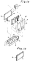
- Figs.1 and 2 illustrate an embodiment of the resistor device in accordance with the present invention wherein electrodes are disposed and attached to both sides of one plate of a PTC element.
- Reference A in the drawings designates a plate of a PTC element having two side surfaces (front side and back side). On one of the side surfaces, which is the front side surface in this particular drawing, a plurality of electrodes 1,2 and 3 are disposed. Each electrode has a size corresponding to a desired resistance value. On the other side of the PTC plate A (back side surface), one electrode 4 is disposed, as illustrated in Fig.1b.
- the PTC element is made from a ceramic member composed of BaTiO3 or compound comprising BaTiO3 or the component elements of the compound or the compound of the same group or series of BaTiO3 or other ceramic or plastic members.
- Reference B in Fig.1a designates a terminal plate comprising an electric insulation plate 50 having terminal portions 5, 6 and 7 protruding from the lower edge thereof and electrode members 8, 9 and 10 disposed on one side surface of the insulation plate 50.
- the electrode members 8, 9 and 10 have sizes corresponding to the sizes of the electrodes 1, 2 and 3 of the PTC element, respectively.
- the electrodes 8, 9 and 10 extend into the protruding terminal portions 5, 6 and 7 of the plate 50, respectively.
- a small projection 11 for engagement is formed on each lateral side of each of the terminal portions 5, 6 and 7.
- Reference C in Fig.1a designates a terminal plate comprising an electric insulation plate 51 having a terminal portion 12 protruding from the lower edge thereof and an electrode member 13 disposed on one side surface of the insulation plate 51.
- the electrode member 13 has a size corresponding to the size of the electrode 4 of the PTC element A (Fig.1b).
- the electrode 13 is formed extending into the protruding terminal portion 12 of the insulation plate 51.
- the terminal protrusion 12 has a small projection 11 on each of lateral sides thereof.
- the PTC element A is sandwiched between the terminal plates B and C in such a way that the electrode members 8, 9 and 10 of the terminal plate B abut against the electrodes 1, 2 and 3 of the PTC element A, respectively and that the electrode 13 of the terminal plate C abuts against the terminal 4 of the PTC element A.
- the sandwich structure is held and secured by a elastic clip 14 and installed in a base holder 15.
- the base holder 15 has a guide groove 17 into which the sandwich structure of the PTC element A interposed between the insulation plates B and C is inserted.
- through-holes 16 are formed at positions corresponding to the protruding terminals 5, 6, 7 and 12 of the terminal plates B and C, respectively. Only one through-hole 16 for the terminal 12 of the plate C is illustrated in Fig.1a.
- the terminal protrusions 5, 6, 7 and 12 are inserted to the corresponding through-holes 16 and penetrate through the base holder 15 and project below the base holder 15.
- the holder 15 has a connector housing 18 formed underside thereof to surround the terminals 5, 6, 7 and 12 projecting below the base holder 15.
- the sandwich structure is installed in the base holder 15 and secured thereto by pressingly inserting the protruding terminals into the through-holes 16 of the guide groove 17 whereby the small projections 11 of each terminal intrude into the inner surface of the through-hole to prevent the terminal protrusions from slipping out from the through-holes and avoid separation of the plates from the holder 15, thus making an assembled structure of the resistor device as illustrated in Fig.2.
- Figs.3 and 4 illustrate another embodiment of the resistor device in accordance with the present invention.
- One plate of PTC element A has a plurality of electrodes 1, 2 and 3 formed on one side surface (front surface in this particular example), as illustrated in Fig.3a. Each electrode has a size corresponding to a desired resistance value.
- the PTC plate A has a plurality of electrodes 21, 22 and 23, each having a size corresponding to a desired resistance value, on the other side surface (back side surface) of the plate A, as illustrated in Fig.3b.
- Numerals 24 and 25 designate terminal plates, each constituting an electrode by itself and having a terminal 26, 27 projecting from the lower edge thereof.
- the terminal plate 24 is pressed against the electrode 1 of the PTC plate A.
- the terminal plate 25 spans over and between the electrodes 2 and 3 of the PTC plate A.
- the terminal plate 25 is pressed against the electrodes 2 and 3.
- the numerals 28 and 29 designate terminal plates, each constituting an electrode by itself and having a terminal 30, 31 projecting from the lower edge thereof.
- the terminal plate 28 is pressed against the two adjacent electrodes 21 and 22 formed on the backside of the PTC element A.
- the terminal plate 29 is pressed against the electrode 23 formed on the backside of the PTC element A.
- the terminal plates are pressed against the electrodes of the PTC element by any appropriate means.
- insulation plates 32 and 33 are disposed in the outside of the terminal plates from both sides of the PTC plate A, as illustrated in Fig.3a, and the vertical layered sandwich structure is held and combined together by the same elastic clip 14 as used in the first embodiment mentioned above.
- the sandwich structure secured by the clip is installed in the base holder 15 in a same manner as the above mentioned first embodiment, that is, by inserting the protruding terminals 26, 27, 30 and 31 into the through-holes 34 of the base holder 15.
- small projections may be formed on the lateral sides of the protruding terminal, as in the case of the first embodiment mentioned above. Or other appropriate means may be adopted to prevent the terminals from slipping out from the through-holes 34.
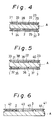
- Fig.4 illustrates a horizontal section of a central portion of the resistor device of Fig.3, showing the contact relation between the PTC element A, electrodes of the element and the terminal plates.
- From the terminal plate 24 disposed in the left end of the front side of the PTC plate A to the terminal plate 29 disposed in the right end of the back side of the PTC plate A is connected in series through the PTC plate and the other terminal plates, that is, from terminal 24 through electrode 1, PTC A, electrode 21, terminal 28, electrode 22, PTC A, electrode 2, terminal 25, electrode 3, PTC A and electrode 23 to the terminal 29.
- various resistance values can be obtained between the two terminals.
- Fig.5 illustrates a horizontal section of a central portion of still another embodiment of the resistor device in accordance with the present invention.
- three electrodes 1, 2 and 3 are disposed on the front surface of the PTC plate A and three electrodes 21, 22 and 23 are also disposed on the back surface of the PTC plate A.
- the six electrodes of the PTC plate A are pressingly covered by six terminal plates 35 to 40, respectively.
- Fig.6 illustrates a horizontal section of a central portion of still another embodiment of the resistor device in accordance with the present invention.
- four electrodes 1, 2, 3 and 41 are disposed on one side surface of a PTC element plate A.
- One terminal plate 43 is disposed spanning between the electrodes 2 and 3 and abuts against the two electrodes 2 and 3.
- terminal plates 42 and 44 are disposed corresponding to the electrodes 1 and 41 and abut against the electrodes, respectively.
- the terminal plate 43 covers the adjacent two electrodes 2 and 3.
- any two electrodes may be covered by one terminal plate.
- the two electrodes may not necessarily be adjacent to each other.
- one terminal plate may cover three electrodes or more. Further, the number of the terminal plates is not limited to three which is the case of the particular embodiment of Fig.6.
- the number of the electrodes of the PTC plate is not limited to that of the first embodiment or the second embodiment wherein three electrodes are disposed in the front surface and one electrode is disposed in the back surface of the PTC plate in accordance with the first embodiment and three electrodes are disposed in each of the two surfaces of the PTC plate in accordance with the second embodiment.
- a plurality of electrodes may be arranged in only one side surface of the PTC plate and a terminal plate is disposed corresponding to each of the electrodes so that any two terminal plates are selected to obtain desired resistance values between the two terminal plates.
- heat radiation fins may be arranged on the outer surface of the insulation plates or the terminal plates to enhance the cooling effect.
- the shape of the PTC element is not limited to the rectangular shape. Any desired shape may be adopted according to the design condition, the characteristic to be obtained or spatial condition of the place to mount the device.
Abstract
Description
- The present invention relates to a resistor device for controlling the rotational speed of a blower motor used is an air conditioning system for instance, one installed in an automobile.
- Resistor devices such as mentioned above are disposed around an outlet of an blower of an air conditioning system of an automobile so that the resistor device is cooled by the wind from the blower.
- A resistor device of this type is disclosed in Japanese Patent Publications (KOKOKU) No.57-45041 and No.57-32482 in which a semiconductor element of positive temperature coefficient (referred to as PTC element hereinafter) is used as the resistor element of the device. The PTC element has such a characteristic, as widely known, that the resistance thereof rises abruptly and greatly when the ambient temperature exceeds a predetermined value (Curie temperature). As a result, when the PTC element is not appropriately cooled when the current is applied thereto or when an excessive current over an allowable extent is applied to the PTC element, the temperature of the PTC element is raised gradually first and when the temperature reaches Curie temperature, the resistance of the element increases suddenly very large so that the current is controlled and the temperature is maintained below the Curie temperature. Accordingly, the PTC element is very useful for proper operation of the motor and avoiding fires in the automobile.
- However, according to the above mentioned Japanese patent publications (57-45041 and 57-32462) aiming at the safety structure for the motor and vehicle, the resistor device is arranged in such a manner that a plurality of ring-shaped PTC element plates and a plurality of terminal plates having a center hole are disposed alternately and combined together by bolt inserted through the center holes of the plates and secured together by a nut screwed on the bolt. In this structure, it is necessary to dispose an insulation spacer between the bolt and the terminal plates to avoid contact and short circuit between the bolt and the terminal plates. As a result, the structure becomes complicated and proper adjustment of the torque for fastening the nut is necessitated, which makes the assembling work troublesome and the cost of the device becomes high.
- The present invention was made considering the above mentioned problems of the related art.
- It is therefore an aim of the present invention to provide a resistor device for blower motor wherein the number of parts is reduced and the resistance against the draught from the blower is decreased, which makes it possible to simplify the structure and raise the reliability of the device.
- Another aim of the present invention is to provide a resistor device for blower motor wherein the productivity of the device is raised and the maintenance of the device can be conveniently carried out.
- Also, it is required that the structure of the resistor device be compact so as to reduce the airflow loss of the blower as much as possible.
- Still another aim of the present invention is to provide a resistor device for a blower motor which satisfies the requirements mentioned above.
- According to the present invention there is provided a resistor device for a blower motor comprising:
a plate-like PTC element having two side surfaces; and a plurality of electrodes disposed on at least one of said two side surfaces. - In another embodiment of resistor device for blower motor according to the present invention, it is desirable that a terminal plate unit comprising a plurality of electrode members be disposed to face to the electrodes of the PTC element plate, each of the electrode members being electrically separated from the other members and having a lead terminal portion.
- In an embodiment of the the resistor device for blower motor according to the present invention, it is desirable that each of the electrode members of the terminal plate unit be formed corresponding to each of the electrodes of the PTC element plate.
- In still another embodiment of the resistor device for blower motor according to the present invention, it is desirable that the terminal plate unit include an electrode member spanning between a plurality of the electrodes of the PTC element plate.
- In a further embodiment of the resistor device for blower motor according to the present invention, it is desirable that only one electrode be disposed on the other side surface of said PTC element plate covering almost entire area of the other side surface.
- In a still further embodiment of the resistor device for blower motor according to the present invention, it is desirable that a plurality of electrodes be also disposed on the other side surface of the PTC element plate.
- In a still further embodiment of the resistor device for blower motor according to the present invention, it is desirable that electrodes be disposed in only one of the side surfaces of the PTC element plate.
- In a still further embodiment of the resistor device for blower motor according to the present invention, it is desirable that the PTC element plate and the terminal plate unit be held and secured together with the use of an elastic clip means.
- In a still further embodiment of the resistor device for blower motor according to the present invention, it is desirable that the electrode member of the terminal plate unit have a lead terminal portion protruding therefrom.
- In a still further embodiment of the resistor device for blower motor according to the present invention, it is desirable that the PTC element plate and the terminal plate unit be installed in a base holder unit in a state being combined together and pressed against each other by inserting the protruding lead terminal portions into through-holes formed in the base holder unit.
- In a still further embodiment of the resistor device for blower motor according to the present invention, it is desirable that a small projection for engagement be formed on a lateral side of each protruding lead terminal portion to prevent the lead terminal portion from slipping out from the through-hole.
- In the arrangement of the present invention mentioned above, the resistor device is constructed in such a manner that on at least one of the side surfaces of one PTC plate, a plurality of electrodes, each having a desired electric resistance, are formed and that a plurality of electrode members of terminal plates are pressingly abutted against the electrodes of the PTC plate. Therefore, only one PTC plate is needed to form the resistor device wherein the PTC plate is sandwiched by terminal plates from the both sides thereof, which makes it possible to realize a resistor device having a regular thickness irrespective of the number of electrodes of the PTC element.
- Therefore, it is an advantage of the present invention that the structure becomes compact as a whole so that the airflow loss is reduced and the current capacity is increased according as the cooling effect is promoted.
- Also, it is another advantage of the present invention that the structure of the base holder for assembling the sandwiched structure of the PTC element can be also simplified so that the number of the parts can be reduced and the device can be assembled easily and reliably.
- Also, the number of the resistance value obtained from the resistor device is the total number of combination from any two of the terminals. For example, if there are four electrode terminals, six kinds of resistance can be obtained from the resistor device. Thus, so many different resistance values can be obtained from one simple structure of the device of the present invention, which raises the industrial applicability of the resistor device.
- It is to be noted that the term terminal plate used in the present invention includes not only the plate which itself is made from a conductive member such as metal constituting an electrode itself but also a structure comprising an electric insulation plate having metal electrodes formed thereon as well.
- The present invention will be further described hereinafter with reference to the following description of exemplary embodiments of the invention and the accompanying drawings, in which:
- Fig. 1a is an exploded perspective view of the resistor device in accordance with an embodiment of the present invention;
- Fig.1b is a perspective view of the PTC element of the device of Fig.1a seen from the back side of the element;
- Fig.2 is a perspective view of an assembly of the resistor device in accordance with the present invention;
- Fig.3a is an exploded perspective view of the resistor device in accordance with another embodiment of the present invention;
- Fig.3b is a perspective view of the PTC element of the device of Fig.3a seen from the back side of the element;
- Fig.4 is a sectional view of the center portion of the resistor device of Fig.3;
- Fig.5 is a sectional view of the center portion of still another embodiment of the resistor device in accordance with the present invention; and
- Fig.6 is a sectional view of the center portion of further embodiment of the resistor device in accordance with the present invention.
- Figs.1 and 2 illustrate an embodiment of the resistor device in accordance with the present invention wherein electrodes are disposed and attached to both sides of one plate of a PTC element. Reference A in the drawings designates a plate of a PTC element having two side surfaces (front side and back side). On one of the side surfaces, which is the front side surface in this particular drawing, a plurality of
electrodes - The PTC element is made from a ceramic member composed of BaTiO₃ or compound comprising BaTiO₃ or the component elements of the compound or the compound of the same group or series of BaTiO₃ or other ceramic or plastic members.
- Reference B in Fig.1a designates a terminal plate comprising an
electric insulation plate 50 havingterminal portions 5, 6 and 7 protruding from the lower edge thereof andelectrode members insulation plate 50. Theelectrode members electrodes electrodes terminal portions 5, 6 and 7 of theplate 50, respectively. Asmall projection 11 for engagement is formed on each lateral side of each of theterminal portions 5, 6 and 7. - Reference C in Fig.1a designates a terminal plate comprising an
electric insulation plate 51 having aterminal portion 12 protruding from the lower edge thereof and anelectrode member 13 disposed on one side surface of theinsulation plate 51. Theelectrode member 13 has a size corresponding to the size of the electrode 4 of the PTC element A (Fig.1b). Theelectrode 13 is formed extending into the protrudingterminal portion 12 of theinsulation plate 51. Theterminal protrusion 12 has asmall projection 11 on each of lateral sides thereof. - In accordance with the present invention, the PTC element A is sandwiched between the terminal plates B and C in such a way that the
electrode members electrodes electrode 13 of the terminal plate C abuts against the terminal 4 of the PTC element A. The sandwich structure is held and secured by aelastic clip 14 and installed in abase holder 15. - The
base holder 15 has aguide groove 17 into which the sandwich structure of the PTC element A interposed between the insulation plates B and C is inserted. In the bottom of thegroove 17, through-holes 16 are formed at positions corresponding to theprotruding terminals hole 16 for theterminal 12 of the plate C is illustrated in Fig.1a. Theterminal protrusions holes 16 and penetrate through thebase holder 15 and project below thebase holder 15. Theholder 15 has aconnector housing 18 formed underside thereof to surround theterminals base holder 15. - The sandwich structure is installed in the
base holder 15 and secured thereto by pressingly inserting the protruding terminals into the through-holes 16 of theguide groove 17 whereby thesmall projections 11 of each terminal intrude into the inner surface of the through-hole to prevent the terminal protrusions from slipping out from the through-holes and avoid separation of the plates from theholder 15, thus making an assembled structure of the resistor device as illustrated in Fig.2. - Figs.3 and 4 illustrate another embodiment of the resistor device in accordance with the present invention. One plate of PTC element A has a plurality of
electrodes electrodes -
Numerals terminal plate 24 is pressed against theelectrode 1 of the PTC plate A. Theterminal plate 25 spans over and between theelectrodes terminal plate 25 is pressed against theelectrodes numerals terminal plate 28 is pressed against the twoadjacent electrodes terminal plate 29 is pressed against theelectrode 23 formed on the backside of the PTC element A. - The terminal plates are pressed against the electrodes of the PTC element by any appropriate means. For example,
insulation plates elastic clip 14 as used in the first embodiment mentioned above. The sandwich structure secured by the clip is installed in thebase holder 15 in a same manner as the above mentioned first embodiment, that is, by inserting the protrudingterminals holes 34 of thebase holder 15. - To avoid separation of the terminal plate from the base holder, small projections (not shown) may be formed on the lateral sides of the protruding terminal, as in the case of the first embodiment mentioned above. Or other appropriate means may be adopted to prevent the terminals from slipping out from the through-
holes 34. - Fig.4 illustrates a horizontal section of a central portion of the resistor device of Fig.3, showing the contact relation between the PTC element A, electrodes of the element and the terminal plates. From the
terminal plate 24 disposed in the left end of the front side of the PTC plate A to theterminal plate 29 disposed in the right end of the back side of the PTC plate A is connected in series through the PTC plate and the other terminal plates, that is, from terminal 24 throughelectrode 1, PTC A,electrode 21,terminal 28,electrode 22, PTC A,electrode 2, terminal 25,electrode 3, PTC A andelectrode 23 to the terminal 29. By selecting any two terminals, various resistance values can be obtained between the two terminals. - Fig.5 illustrates a horizontal section of a central portion of still another embodiment of the resistor device in accordance with the present invention. In this embodiment, three
electrodes electrodes - Fig.6 illustrates a horizontal section of a central portion of still another embodiment of the resistor device in accordance with the present invention. In this embodiment, four
electrodes terminal plate 43 is disposed spanning between theelectrodes electrodes terminal plates electrodes - In the embodiment of Fig.6, the
terminal plate 43 covers the adjacent twoelectrodes - It is also to be noted that the number of the electrodes of the PTC plate is not limited to that of the first embodiment or the second embodiment wherein three electrodes are disposed in the front surface and one electrode is disposed in the back surface of the PTC plate in accordance with the first embodiment and three electrodes are disposed in each of the two surfaces of the PTC plate in accordance with the second embodiment.
- Also, a plurality of electrodes may be arranged in only one side surface of the PTC plate and a terminal plate is disposed corresponding to each of the electrodes so that any two terminal plates are selected to obtain desired resistance values between the two terminal plates. Further, heat radiation fins may be arranged on the outer surface of the insulation plates or the terminal plates to enhance the cooling effect.
- It is also to be noted that the shape of the PTC element is not limited to the rectangular shape. Any desired shape may be adopted according to the design condition, the characteristic to be obtained or spatial condition of the place to mount the device.
Claims (11)
- A resistor device for a blower motor comprising:
a plate-like PTC element having two side surfaces; and a plurality of electrodes disposed on at least one of said two side surfaces. - A resistor device according to claim 1, wherein a terminal plate means comprises a plurality of electrode members disposed opposite to said electrodes of the PTC element plate, each of said electrode members being electrically separated from the other members and having a lead terminal portion.
- A resistor device according to claim 2, wherein each of said electrode members of said terminal plate means corresponds to one of said electrodes of said PTC element plate.
- A resistor device according to claim 2, whereinsaid terminal plate means includes an electrode member spanning between a plurality of said electrodes of said PTC element plate.
- A resistor device according to claim 1, wherein a single electrode is disposed on the other side surface of said PTC element plate covering substantially the entire area of the other side surface.
- A resistor device according to claim 1, wherein a plurality of electrodes are disposed on the other side surface of said PTC element plate.
- A resistor device according to claim 1, wherein electrodes are disposed on only one of the side surfaces of said PTC element plate.
- A resistor device according to claim 2, wherein said PTC element plate and said terminal plate means are held and secured together with the use of an elastic clip means.
- A resistor device according to claim 2, wherein said electrode member of said terminal plate means has a lead terminal portion protruding therefrom.
- A resistor device according to claim 9, wherein said PTC element plate and said terminal plate means are installed in a base holder means in a state being combined together and pressed against each other by inserting said protruding lead terminal portions into through-holes formed in said base holder means.
- A resistor device according to claim 10, wherein a small projection for engagement is formed on a lateral side of each protruding lead terminal portion to prevent said lead terminal portion from slipping out from said through-hole.
Applications Claiming Priority (4)
| Application Number | Priority Date | Filing Date | Title |
|---|---|---|---|
| JP324952/90 | 1990-11-26 | ||
| JP32495290 | 1990-11-26 | ||
| JP3142284A JP2741434B2 (en) | 1990-11-26 | 1991-03-30 | Blower motor resistor |
| JP142284/91 | 1991-03-30 |
Publications (2)
| Publication Number | Publication Date |
|---|---|
| EP0489528A1 true EP0489528A1 (en) | 1992-06-10 |
| EP0489528B1 EP0489528B1 (en) | 1996-02-21 |
Family
ID=26474346
Family Applications (1)
| Application Number | Title | Priority Date | Filing Date |
|---|---|---|---|
| EP91310891A Expired - Lifetime EP0489528B1 (en) | 1990-11-26 | 1991-11-26 | Resistor device for blower motor |
Country Status (15)
| Country | Link |
|---|---|
| US (1) | US5268665A (en) |
| EP (1) | EP0489528B1 (en) |
| JP (1) | JP2741434B2 (en) |
| KR (1) | KR100244927B1 (en) |
| CN (1) | CN1026368C (en) |
| AU (1) | AU655606B2 (en) |
| BR (1) | BR9105145A (en) |
| CA (1) | CA2056115C (en) |
| DE (1) | DE69117271T2 (en) |
| ES (1) | ES2050583B1 (en) |
| FR (1) | FR2669764B1 (en) |
| IT (1) | IT1252282B (en) |
| RU (1) | RU2018987C1 (en) |
| TW (1) | TW215500B (en) |
| UA (1) | UA25923A1 (en) |
Cited By (3)
| Publication number | Priority date | Publication date | Assignee | Title |
|---|---|---|---|---|
| WO1997049102A1 (en) * | 1996-06-19 | 1997-12-24 | Littelfuse, Inc. | Electrical apparatus for overcurrent protection of electrical circuits |
| WO2000016345A1 (en) * | 1998-09-15 | 2000-03-23 | Littelfuse, Inc. | Electrical apparatus for overcurrent protection of electrical circuits |
| EP3584808A1 (en) * | 2018-06-18 | 2019-12-25 | Mahle International GmbH | Ptc heating module for heating a fluid |
Families Citing this family (16)
| Publication number | Priority date | Publication date | Assignee | Title |
|---|---|---|---|---|
| US5408575A (en) * | 1992-06-01 | 1995-04-18 | International Resistive Company, Inc. | Automotive fan controller |
| KR960701454A (en) * | 1994-01-31 | 1996-02-24 | 마츠모토 쇼죠 | PTC surface heater and its resistance adjustment method |
| AU5678496A (en) * | 1995-05-10 | 1996-11-29 | Littelfuse, Inc. | Ptc circuit protection device and manufacturing process for same |
| US5663702A (en) * | 1995-06-07 | 1997-09-02 | Littelfuse, Inc. | PTC electrical device having fuse link in series and metallized ceramic electrodes |
| JPH09240250A (en) * | 1995-12-27 | 1997-09-16 | Karusonitsuku Prod Kk | Resistor |
| US6023403A (en) * | 1996-05-03 | 2000-02-08 | Littlefuse, Inc. | Surface mountable electrical device comprising a PTC and fusible element |
| US5841341A (en) * | 1996-09-27 | 1998-11-24 | Therm-O-Disc, Incorporated | Clip for PTC devices |
| US6282072B1 (en) | 1998-02-24 | 2001-08-28 | Littelfuse, Inc. | Electrical devices having a polymer PTC array |
| US6582647B1 (en) | 1998-10-01 | 2003-06-24 | Littelfuse, Inc. | Method for heat treating PTC devices |
| JP2001044003A (en) * | 1999-07-29 | 2001-02-16 | Sony Chem Corp | Protective element |
| US6747542B1 (en) * | 2000-08-14 | 2004-06-08 | Delphi Technologies, Inc. | Snap-in blow motor speed control with brakeaway service feature |
| US6628498B2 (en) | 2000-08-28 | 2003-09-30 | Steven J. Whitney | Integrated electrostatic discharge and overcurrent device |
| TW487272U (en) * | 2001-03-20 | 2002-05-11 | Polytronics Technology Corp | Multilayer circuit boards |
| US7183891B2 (en) | 2002-04-08 | 2007-02-27 | Littelfuse, Inc. | Direct application voltage variable material, devices employing same and methods of manufacturing such devices |
| US7543632B2 (en) | 2006-01-09 | 2009-06-09 | Delphi Technologies, Inc. | Compact circuit board for an automotive HVAC system |
| DE102017208253A1 (en) * | 2017-05-16 | 2018-11-22 | Eberspächer Catem Gmbh & Co. Kg | Method for producing a PTC heating element |
Citations (4)
| Publication number | Priority date | Publication date | Assignee | Title |
|---|---|---|---|---|
| US3691503A (en) * | 1971-09-29 | 1972-09-12 | Carborundum Co | Variable resistance resistor assembly |
| FR2348614A1 (en) * | 1976-04-15 | 1977-11-10 | Philips Nv | ELECTRIC HEATING DEVICE INCLUDING A RESISTANCE BODY IN MATERIAL WITH A POSITIVE TEMPERATURE COEFFICIENT |
| FR2392521A1 (en) * | 1977-05-28 | 1978-12-22 | Sueddeutsche Kuehler Behr | CIRCUIT WITH PROTECTION AGAINST OVERLOADS FOR GRADUAL ADJUSTMENT OF THE POWER OF ELECTRIC FAN MOTORS |
| EP0363191A2 (en) * | 1988-10-07 | 1990-04-11 | Fujikura Ltd. | Flat resistance for blower control unit of automobile air conditioner and blower control unit using the same |
Family Cites Families (4)
| Publication number | Priority date | Publication date | Assignee | Title |
|---|---|---|---|---|
| US4408244A (en) * | 1978-06-08 | 1983-10-04 | Suddeutsche Kuhlerfabrik Julius Fr. Behr Gmbh & Co. Kg | Circuit safe against overload for varying the amount of power to an electric blower motor |
| JPS56131954A (en) * | 1980-03-19 | 1981-10-15 | Nippon Telegr & Teleph Corp <Ntt> | Semiconductor device |
| GB8604519D0 (en) * | 1986-02-24 | 1986-04-03 | Raychem Sa Nv | Electrical devices |
| KR920000868Y1 (en) * | 1988-07-08 | 1992-01-31 | 지이제루 기기 가부시기가이샤 | Control device for a blower |
-
1991
- 1991-03-30 JP JP3142284A patent/JP2741434B2/en not_active Expired - Fee Related
- 1991-11-15 TW TW080108982A patent/TW215500B/zh active
- 1991-11-19 AU AU87990/91A patent/AU655606B2/en not_active Ceased
- 1991-11-20 IT ITMI913094A patent/IT1252282B/en active IP Right Grant
- 1991-11-20 US US07/797,737 patent/US5268665A/en not_active Expired - Fee Related
- 1991-11-22 BR BR919105145A patent/BR9105145A/en not_active IP Right Cessation
- 1991-11-22 ES ES09102604A patent/ES2050583B1/en not_active Expired - Lifetime
- 1991-11-25 UA UA5010212A patent/UA25923A1/en unknown
- 1991-11-25 FR FR9114482A patent/FR2669764B1/en not_active Expired - Fee Related
- 1991-11-25 RU SU915010212A patent/RU2018987C1/en active
- 1991-11-25 CA CA002056115A patent/CA2056115C/en not_active Expired - Fee Related
- 1991-11-26 EP EP91310891A patent/EP0489528B1/en not_active Expired - Lifetime
- 1991-11-26 CN CN91111025A patent/CN1026368C/en not_active Expired - Fee Related
- 1991-11-26 KR KR1019910021227A patent/KR100244927B1/en not_active IP Right Cessation
- 1991-11-26 DE DE69117271T patent/DE69117271T2/en not_active Expired - Fee Related
Patent Citations (4)
| Publication number | Priority date | Publication date | Assignee | Title |
|---|---|---|---|---|
| US3691503A (en) * | 1971-09-29 | 1972-09-12 | Carborundum Co | Variable resistance resistor assembly |
| FR2348614A1 (en) * | 1976-04-15 | 1977-11-10 | Philips Nv | ELECTRIC HEATING DEVICE INCLUDING A RESISTANCE BODY IN MATERIAL WITH A POSITIVE TEMPERATURE COEFFICIENT |
| FR2392521A1 (en) * | 1977-05-28 | 1978-12-22 | Sueddeutsche Kuehler Behr | CIRCUIT WITH PROTECTION AGAINST OVERLOADS FOR GRADUAL ADJUSTMENT OF THE POWER OF ELECTRIC FAN MOTORS |
| EP0363191A2 (en) * | 1988-10-07 | 1990-04-11 | Fujikura Ltd. | Flat resistance for blower control unit of automobile air conditioner and blower control unit using the same |
Cited By (4)
| Publication number | Priority date | Publication date | Assignee | Title |
|---|---|---|---|---|
| WO1997049102A1 (en) * | 1996-06-19 | 1997-12-24 | Littelfuse, Inc. | Electrical apparatus for overcurrent protection of electrical circuits |
| WO2000016345A1 (en) * | 1998-09-15 | 2000-03-23 | Littelfuse, Inc. | Electrical apparatus for overcurrent protection of electrical circuits |
| EP3584808A1 (en) * | 2018-06-18 | 2019-12-25 | Mahle International GmbH | Ptc heating module for heating a fluid |
| EP3584808B1 (en) | 2018-06-18 | 2021-10-06 | Mahle International GmbH | Ptc heating module for heating a fluid |
Also Published As
| Publication number | Publication date |
|---|---|
| CA2056115A1 (en) | 1992-05-27 |
| EP0489528B1 (en) | 1996-02-21 |
| JPH04229601A (en) | 1992-08-19 |
| IT1252282B (en) | 1995-06-08 |
| AU655606B2 (en) | 1995-01-05 |
| US5268665A (en) | 1993-12-07 |
| RU2018987C1 (en) | 1994-08-30 |
| JP2741434B2 (en) | 1998-04-15 |
| ES2050583R (en) | 1995-05-01 |
| FR2669764B1 (en) | 1997-01-31 |
| FR2669764A1 (en) | 1992-05-29 |
| AU8799091A (en) | 1992-05-28 |
| ES2050583B1 (en) | 1995-11-16 |
| BR9105145A (en) | 1992-07-21 |
| CA2056115C (en) | 2001-03-06 |
| KR100244927B1 (en) | 2000-03-02 |
| ITMI913094A0 (en) | 1991-11-20 |
| DE69117271D1 (en) | 1996-03-28 |
| UA25923A1 (en) | 1999-02-26 |
| TW215500B (en) | 1993-11-01 |
| ES2050583A2 (en) | 1994-05-16 |
| ITMI913094A1 (en) | 1993-05-20 |
| CN1062807A (en) | 1992-07-15 |
| CN1026368C (en) | 1994-10-26 |
| DE69117271T2 (en) | 1996-07-18 |
| KR920011024A (en) | 1992-06-27 |
Similar Documents
| Publication | Publication Date | Title |
|---|---|---|
| EP0489528B1 (en) | Resistor device for blower motor | |
| US5256857A (en) | Finned PTC air heater assembly for heating an automotive passenger compartment | |
| EP0489529B1 (en) | Resistor device for blower motor | |
| EP0616486A1 (en) | Heater apparatus and process for heating a fluid stream | |
| CA2173357C (en) | Electrical assembly | |
| US5140205A (en) | Temperature control in an electric motor | |
| EP1130337A2 (en) | Electric radiator | |
| US5909168A (en) | PTC conductive polymer devices | |
| US4414530A (en) | Miniature motor protector apparatus and method for assembling thereof | |
| KR20070000769A (en) | Resistor for blower motor | |
| JPS6212641B2 (en) | ||
| JP3817837B2 (en) | Resistor for speed control of vehicle blower | |
| JP2568223Y2 (en) | Resistor | |
| RU2020620C1 (en) | Resistive device for fan motor | |
| JP2559162Y2 (en) | Blower motor resistor | |
| KR100196325B1 (en) | Resistance for controlling the motion of a blower | |
| JPH0965618A (en) | Ptc device | |
| US5867086A (en) | Resistor unit for a fan speed controller of an automotive air conditioning device | |
| KR100359245B1 (en) | Ptc resistance assembly of blower motor | |
| JPS5914665Y2 (en) | Blower control device | |
| KR950003082B1 (en) | Resistor | |
| JP2528874Y2 (en) | Blower motor resistor | |
| JPH0445202Y2 (en) | ||
| KR100317710B1 (en) | P.t.c resistance assembly of a blower motor | |
| JPS6323902Y2 (en) |
Legal Events
| Date | Code | Title | Description |
|---|---|---|---|
| PUAI | Public reference made under article 153(3) epc to a published international application that has entered the european phase |
Free format text: ORIGINAL CODE: 0009012 |
|
| AK | Designated contracting states |
Kind code of ref document: A1 Designated state(s): DE GB SE |
|
| 17P | Request for examination filed |
Effective date: 19921211 |
|
| 17Q | First examination report despatched |
Effective date: 19950209 |
|
| GRAA | (expected) grant |
Free format text: ORIGINAL CODE: 0009210 |
|
| AK | Designated contracting states |
Kind code of ref document: B1 Designated state(s): DE GB SE |
|
| REF | Corresponds to: |
Ref document number: 69117271 Country of ref document: DE Date of ref document: 19960328 |
|
| PLBE | No opposition filed within time limit |
Free format text: ORIGINAL CODE: 0009261 |
|
| STAA | Information on the status of an ep patent application or granted ep patent |
Free format text: STATUS: NO OPPOSITION FILED WITHIN TIME LIMIT |
|
| 26N | No opposition filed | ||
| PGFP | Annual fee paid to national office [announced via postgrant information from national office to epo] |
Ref country code: SE Payment date: 20001106 Year of fee payment: 10 |
|
| PGFP | Annual fee paid to national office [announced via postgrant information from national office to epo] |
Ref country code: DE Payment date: 20001120 Year of fee payment: 10 |
|
| PGFP | Annual fee paid to national office [announced via postgrant information from national office to epo] |
Ref country code: GB Payment date: 20001122 Year of fee payment: 10 |
|
| PG25 | Lapsed in a contracting state [announced via postgrant information from national office to epo] |
Ref country code: GB Free format text: LAPSE BECAUSE OF NON-PAYMENT OF DUE FEES Effective date: 20011126 |
|
| PG25 | Lapsed in a contracting state [announced via postgrant information from national office to epo] |
Ref country code: SE Free format text: LAPSE BECAUSE OF NON-PAYMENT OF DUE FEES Effective date: 20011127 |
|
| REG | Reference to a national code |
Ref country code: GB Ref legal event code: IF02 |
|
| EUG | Se: european patent has lapsed |
Ref document number: 91310891.6 |
|
| PG25 | Lapsed in a contracting state [announced via postgrant information from national office to epo] |
Ref country code: DE Free format text: LAPSE BECAUSE OF NON-PAYMENT OF DUE FEES Effective date: 20020702 |
|
| GBPC | Gb: european patent ceased through non-payment of renewal fee |
Effective date: 20011126 |