EP0489476B1 - Rapid start fluorescent lamp having quick hot restarting - Google Patents
Rapid start fluorescent lamp having quick hot restarting Download PDFInfo
- Publication number
- EP0489476B1 EP0489476B1 EP91203160A EP91203160A EP0489476B1 EP 0489476 B1 EP0489476 B1 EP 0489476B1 EP 91203160 A EP91203160 A EP 91203160A EP 91203160 A EP91203160 A EP 91203160A EP 0489476 B1 EP0489476 B1 EP 0489476B1
- Authority
- EP
- European Patent Office
- Prior art keywords
- lamp
- cathode
- switch means
- fluorescent lamp
- envelope
- Prior art date
- Legal status (The legal status is an assumption and is not a legal conclusion. Google has not performed a legal analysis and makes no representation as to the accuracy of the status listed.)
- Expired - Lifetime
Links
- 238000010438 heat treatment Methods 0.000 description 14
- 239000011521 glass Substances 0.000 description 5
- XEEYBQQBJWHFJM-UHFFFAOYSA-N Iron Chemical compound [Fe] XEEYBQQBJWHFJM-UHFFFAOYSA-N 0.000 description 4
- PXHVJJICTQNCMI-UHFFFAOYSA-N Nickel Chemical compound [Ni] PXHVJJICTQNCMI-UHFFFAOYSA-N 0.000 description 4
- 230000004913 activation Effects 0.000 description 4
- 239000000463 material Substances 0.000 description 4
- 239000011248 coating agent Substances 0.000 description 2
- 238000000576 coating method Methods 0.000 description 2
- 229910052742 iron Inorganic materials 0.000 description 2
- 238000004519 manufacturing process Methods 0.000 description 2
- 238000012986 modification Methods 0.000 description 2
- 230000004048 modification Effects 0.000 description 2
- 229910052759 nickel Inorganic materials 0.000 description 2
- 230000002028 premature Effects 0.000 description 2
- VYZAMTAEIAYCRO-UHFFFAOYSA-N Chromium Chemical compound [Cr] VYZAMTAEIAYCRO-UHFFFAOYSA-N 0.000 description 1
- OAICVXFJPJFONN-UHFFFAOYSA-N Phosphorus Chemical compound [P] OAICVXFJPJFONN-UHFFFAOYSA-N 0.000 description 1
- 238000007664 blowing Methods 0.000 description 1
- 230000001419 dependent effect Effects 0.000 description 1
- 239000000203 mixture Substances 0.000 description 1
- WFKWXMTUELFFGS-UHFFFAOYSA-N tungsten Chemical compound [W] WFKWXMTUELFFGS-UHFFFAOYSA-N 0.000 description 1
- 229910052721 tungsten Inorganic materials 0.000 description 1
- 239000010937 tungsten Substances 0.000 description 1
Images

Classifications
-
- H—ELECTRICITY
- H01—ELECTRIC ELEMENTS
- H01J—ELECTRIC DISCHARGE TUBES OR DISCHARGE LAMPS
- H01J61/00—Gas-discharge or vapour-discharge lamps
- H01J61/02—Details
- H01J61/54—Igniting arrangements, e.g. promoting ionisation for starting
- H01J61/541—Igniting arrangements, e.g. promoting ionisation for starting using a bimetal switch
-
- Y—GENERAL TAGGING OF NEW TECHNOLOGICAL DEVELOPMENTS; GENERAL TAGGING OF CROSS-SECTIONAL TECHNOLOGIES SPANNING OVER SEVERAL SECTIONS OF THE IPC; TECHNICAL SUBJECTS COVERED BY FORMER USPC CROSS-REFERENCE ART COLLECTIONS [XRACs] AND DIGESTS
- Y10—TECHNICAL SUBJECTS COVERED BY FORMER USPC
- Y10S—TECHNICAL SUBJECTS COVERED BY FORMER USPC CROSS-REFERENCE ART COLLECTIONS [XRACs] AND DIGESTS
- Y10S315/00—Electric lamp and discharge devices: systems
- Y10S315/05—Starting and operating circuit for fluorescent lamp
Definitions
- the invention relates to fluorescent lamps of the so-called "rapid start” type. Such lamps are provided with thermal switches, responsive to cathode (filament) heat, for turning off the cathode heating current after starting and during lamp operation.
- Rapid start fluorescent lamps are provided with cathode heating current, for heating the cathodes to electron-emitting temperature so that the lamps start quickly without damaging the electron-emitting material of the cathodes.
- the cathode heating consumes about one and one-half to two watts of electrical power per cathode. While the lamps are operating, the cathodes can provide adequate electron emission without the need for the supply of heating current to the cathodes. Accordingly, turning off the cathode heating current when the lamps are operating can save about three or four watts of electrical energy per lamp, resulting in considerable energy and money savings in lighting systems.
- U.S. Pat. Nos. 4,097,779 and 4,114,968 disclose rapid start fluorescent lamps provided with a thermal cutout switch near each cathode, and in electrical series with the associated cathode, for turning off the cathode current after the lamps start and while they are operating.
- These patents disclose U-shaped bimetal switches sealed in glass envelopes which are mounted near each cathode. After each cathode is heated sufficiently by the heating current heat from the cathode causes the nearby bimetal switch member to bend and open the current circuit to the cathode.
- the manufacture of fluorescent lamps involves coating the tungsten cathode coils with an electron emission coating. After the lamps are assembled, the cathodes are "activated” by passing current through them to heat them. However, the cathode current cutout switches in the lamps will turn off the activation cathode heating current prior to complete activation of the cathodes.
- U.S. Pat. No. 4,114,968 solves this problem by connecting fuse wires across the thermal switch, for shorting the switch and permitting activation of the cathodes. The fuses are then "blown” (severed), by applying an electrical pulse through each of the series-connected fuses and cathodes.
- the fuses must be able to carry the cathode activation current and also be capable of being "blown” by a current pulse of insufficient strength to damage the cathode. Fuse timing is also important, since the fuse-blowing pulse must be applied while the thermal switch is in open condition so it will not short-circuit the pulse away from the fuse.
- the quick start designs currently being marketed share a common problem: hot restarting.
- hot restarting When the lamps are turned off after the switches have opened, a cool-off period is required to allow the switches to close, thus permitting current to flow through the cathode and restart the lamp.
- a series of tests were performed on rapid start lamps from various manufacturers to determine the restart time in a worst case scenario. The test consisted of operating the lamps for 20 minutes at an ambient temperature of 198°C (110°F), which is the approximate temperature that the lamps experience in a standard four-lamp fixture. The lamps were then shut off for approximately two seconds and turned back on at 108 volts. The time that was required for the lamps to start was recorded. The times recorded for three major lamps manufacturers ranged from 52 to 68 seconds. All of these restart times are longer than would be considered acceptable by the consumer.
- the present invention is directed toward providing a rapid start lamp having a considerably shorter hot restart time.
- This invention is directed to a rapid start fluorescent lamp according to claim 1 having an improved hot restarting time.
- the lamp includes the standard envelope and end cap through which electrical connection is made by conductive feedthroughs which extend through the lamp stem to the interior of the lamp.
- One of the feedthroughs is connected to the cathode (filament means), the other of is connected to the leads of a fusible element (fuse means) which is contained within an envelope to isolate the fusible element from the lamp environment.
- a thermally activated bimetallic element is disposed across the leads of the fuse. The other lead of the fusible element is connected to the other end of the cathode.
- the bimetal element When the bimetal element is cold, it will bridge the connection between the other feedthrough to the other end of the cathode to permit rapid starting by application of heating current. When the bimetal heats up, the connection of both ends of the cathode to the heating current is broken.
- the fusible element is enclosed within a container and is thus isolated from the lamp environment.
- the bimetallic element since it is not located within the container may be is larger than that of previous lamps.
- the bimetallic element is positioned beneath the upper surface of the glass seal through which the feedthrough wires extend.
- the heat radiated by the arc glow and the heating of the filament prior to lamp starting does not cause premature opening of the switch which could prevent the lamp for starting.
- This positioning also permits rapid closing of the switch when the lamp is shut off thus permitting quicker hot restarting.
- the cathode mount feedthroughs and fusible element are arranged in an economical manner which utilizes the leads of the fusible element as a supporting structure for the bimetallic switch, thus saving materials and expense, which are important considerations for mass produced lamps.
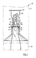
- FIG. 1 illustrates a fluorescent lamp 10 which includes a glass envelope 12 and an end cap 14 of any standard design.
- Envelope 12 is generally constructed of glass and coated internally with a phosphor material and containing a gas fill as is known to those skilled in the art.
- Extending away from end cap 14 is a glass stem 16 through whose upper surface extend conductive feedthroughs 18, 20 which are connected to electrical connectors on end cap 14 and thereafter to the source of current.
- Feedthrough 20 provides electrical connection and mechanical support to one end of a cathode 22.
- the upper surface of stem 16 has been illustrated as flat, however a flat surface is not necessary as it may be of any configuration.
- an enclosed fuse assembly 24 which includes a container 26 and a pair of lead wires 28, 30. Connected internally within container 24 between lead wires 28, 30 is a fusible (frangible) element 32. Fusible element 32 is mounted within container 24 so that it is isolated from the environment of envelope 12 which permits fusible element 32 to be blown after actuation of cathode 22 during lamp manufacture without contaminating the lamp environment. After fusible element 32 is severed it plays no part in the electrical connection of cathode 22. However fuse assembly 24 at all times serves as part of the mechanical support of the cathode and thermal switch.
- Lead 28 of fuse 24 is electrically and mechanically joined to feedthrough 18 by means of a connecting wire 34 which extends toward envelope 12.
- the lower end 36 of lead 28 of fuse 24 extends parallel to but beneath the upper surface 38 of lamp stem 16.
- Lead 30 of fuse 24 is connected to a wire 40 which leads upwardly and joins a support rod 42 which is connected to the other end of cathode 22.
- the lower portion 44 of lead 30 of fuse 24 also extends parallel and beneath the upper surface 38 of lamp stem 16.
- a bimetallic element 46 extends between portions 36 and 44 of fuse leads 28, 30 so as to provide electrical connection therebetween when it is unheated.
- One end of bimetallic element 46 is fixed to portion 36 of lead 28 and the other end of bimetallic element 46 contacts portion 44 of lead 30 when unheated.
- the free end will be biased away from contact with portion 44 of lead 30 to break the electrical connection between leads 28 and 30 and thus cut off the supply of heating current to cathode 22.
- bimetallic element 46 In operation, upon cold starting, bimetallic element 46 will be in engagement of arm 34 of lead 30. Thus, an electrical connection will be made between feedthrough 18, connecting wire 34, fuse lead 28, bimetallic element 46, fuse lead 30, wire 40, support arm 42, cathode 22 and feedthrough 20. Accordingly, heating current will flow to cathode 22 for starting. After lamp 10 becomes lit, the heat of the lamp operation causes the free end of bimetallic element 46 to be biased away from arm 44 to break the electrical connection between feedthroughs 18 and 20 to cathode 22. Thus, only feedthrough 20 will be connected to cathode 22.
- bimetallic element 46 outside of fuse container 26 and its positioning according to the invention beneath the upper surface 38 of lamp stem 16 permits a larger than usual bimetallic element 46 to be utilized. Suitable dimensions are on the order of 14.45 x 3.25 x 0.15 millimetres. Suitable material for bimetallic element 46 is 40% nickel and 60% iron on the low expansion side and 75% nickel, 22% iron and 3% chrome on the high expansion side. Of course, the dimensions and composition may be varied depending on the application and desired operational parameters. In the location illustrated, the heat radiated by the arc glow of cathode 22 and its heating prior to starting will not cause premature opening of bimetallic element 46, which would prevent the lamp from starting. Tests indicate that the hot restarting time of a lamp constructed in accordance with the present invention is on the order of 30 seconds which is less than half the time of conventionally designed lamps. Clearly this delay is more acceptable to the consumer.
Landscapes
- Discharge Lamps And Accessories Thereof (AREA)
- Circuit Arrangements For Discharge Lamps (AREA)
Description
- The invention relates to fluorescent lamps of the so-called "rapid start" type. Such lamps are provided with thermal switches, responsive to cathode (filament) heat, for turning off the cathode heating current after starting and during lamp operation.
- Rapid start fluorescent lamps are provided with cathode heating current, for heating the cathodes to electron-emitting temperature so that the lamps start quickly without damaging the electron-emitting material of the cathodes. The cathode heating consumes about one and one-half to two watts of electrical power per cathode. While the lamps are operating, the cathodes can provide adequate electron emission without the need for the supply of heating current to the cathodes. Accordingly, turning off the cathode heating current when the lamps are operating can save about three or four watts of electrical energy per lamp, resulting in considerable energy and money savings in lighting systems. In this regard, see U.S. Patent No. 4,517,493.
- U.S. Pat. Nos. 4,097,779 and 4,114,968 disclose rapid start fluorescent lamps provided with a thermal cutout switch near each cathode, and in electrical series with the associated cathode, for turning off the cathode current after the lamps start and while they are operating. These patents disclose U-shaped bimetal switches sealed in glass envelopes which are mounted near each cathode. After each cathode is heated sufficiently by the heating current heat from the cathode causes the nearby bimetal switch member to bend and open the current circuit to the cathode.
- The manufacture of fluorescent lamps involves coating the tungsten cathode coils with an electron emission coating. After the lamps are assembled, the cathodes are "activated" by passing current through them to heat them. However, the cathode current cutout switches in the lamps will turn off the activation cathode heating current prior to complete activation of the cathodes. U.S. Pat. No. 4,114,968 solves this problem by connecting fuse wires across the thermal switch, for shorting the switch and permitting activation of the cathodes. The fuses are then "blown" (severed), by applying an electrical pulse through each of the series-connected fuses and cathodes. The fuses must be able to carry the cathode activation current and also be capable of being "blown" by a current pulse of insufficient strength to damage the cathode. Fuse timing is also important, since the fuse-blowing pulse must be applied while the thermal switch is in open condition so it will not short-circuit the pulse away from the fuse.
- Similar lamps are known from US-A-4 528 479 and US-A-4 709 187.
- The quick start designs currently being marketed share a common problem: hot restarting. When the lamps are turned off after the switches have opened, a cool-off period is required to allow the switches to close, thus permitting current to flow through the cathode and restart the lamp. A series of tests were performed on rapid start lamps from various manufacturers to determine the restart time in a worst case scenario. The test consisted of operating the lamps for 20 minutes at an ambient temperature of 198°C (110°F), which is the approximate temperature that the lamps experience in a standard four-lamp fixture. The lamps were then shut off for approximately two seconds and turned back on at 108 volts. The time that was required for the lamps to start was recorded. The times recorded for three major lamps manufacturers ranged from 52 to 68 seconds. All of these restart times are longer than would be considered acceptable by the consumer. The present invention is directed toward providing a rapid start lamp having a considerably shorter hot restart time.
- This invention is directed to a rapid start fluorescent lamp according to
claim 1 having an improved hot restarting time. The lamp includes the standard envelope and end cap through which electrical connection is made by conductive feedthroughs which extend through the lamp stem to the interior of the lamp. One of the feedthroughs is connected to the cathode (filament means), the other of is connected to the leads of a fusible element (fuse means) which is contained within an envelope to isolate the fusible element from the lamp environment. A thermally activated bimetallic element is disposed across the leads of the fuse. The other lead of the fusible element is connected to the other end of the cathode. When the bimetal element is cold, it will bridge the connection between the other feedthrough to the other end of the cathode to permit rapid starting by application of heating current. When the bimetal heats up, the connection of both ends of the cathode to the heating current is broken. - In this design, the fusible element is enclosed within a container and is thus isolated from the lamp environment. However, the bimetallic element, since it is not located within the container may be is larger than that of previous lamps.
- According to the invention, the bimetallic element is positioned beneath the upper surface of the glass seal through which the feedthrough wires extend. By placing the bimetallic element in this location, the heat radiated by the arc glow and the heating of the filament prior to lamp starting does not cause premature opening of the switch which could prevent the lamp for starting. This positioning also permits rapid closing of the switch when the lamp is shut off thus permitting quicker hot restarting. Additionally, the cathode mount feedthroughs and fusible element are arranged in an economical manner which utilizes the leads of the fusible element as a supporting structure for the bimetallic switch, thus saving materials and expense, which are important considerations for mass produced lamps.
- The dependent claims describe particular embodiments of the invention.
- For a better understanding of the invention, reference is made to the following drawings which are to be taken in connection with the detailed specification to follow:
- Fig. 1 is a front view of the cathode mount and bimetallic element constructed in accordance with the present invention; and
- Figs. 2 and 3 are a side view and a top view of the arrangement of Fig. 1.
- The drawings illustrate a
fluorescent lamp 10 which includes aglass envelope 12 and anend cap 14 of any standard design.Envelope 12 is generally constructed of glass and coated internally with a phosphor material and containing a gas fill as is known to those skilled in the art. Extending away fromend cap 14 is aglass stem 16 through whose upper surface extendconductive feedthroughs end cap 14 and thereafter to the source of current. Feedthrough 20 provides electrical connection and mechanical support to one end of acathode 22. The upper surface ofstem 16 has been illustrated as flat, however a flat surface is not necessary as it may be of any configuration. - Also mounted within
envelope 12 is an enclosedfuse assembly 24, which includes acontainer 26 and a pair oflead wires container 24 betweenlead wires element 32.Fusible element 32 is mounted withincontainer 24 so that it is isolated from the environment ofenvelope 12 which permitsfusible element 32 to be blown after actuation ofcathode 22 during lamp manufacture without contaminating the lamp environment. Afterfusible element 32 is severed it plays no part in the electrical connection ofcathode 22. Howeverfuse assembly 24 at all times serves as part of the mechanical support of the cathode and thermal switch. -
Lead 28 offuse 24 is electrically and mechanically joined tofeedthrough 18 by means of a connectingwire 34 which extends towardenvelope 12. Thelower end 36 oflead 28 offuse 24 extends parallel to but beneath theupper surface 38 oflamp stem 16.Lead 30 offuse 24 is connected to a wire 40 which leads upwardly and joins asupport rod 42 which is connected to the other end ofcathode 22. Thelower portion 44 oflead 30 offuse 24 also extends parallel and beneath theupper surface 38 oflamp stem 16. - A
bimetallic element 46 extends betweenportions bimetallic element 46 is fixed toportion 36 oflead 28 and the other end ofbimetallic element 46contacts portion 44 oflead 30 when unheated. Whenbimetallic element 46 is heated, the free end will be biased away from contact withportion 44 oflead 30 to break the electrical connection between leads 28 and 30 and thus cut off the supply of heating current tocathode 22. - In operation, upon cold starting,
bimetallic element 46 will be in engagement ofarm 34 oflead 30. Thus, an electrical connection will be made betweenfeedthrough 18, connectingwire 34,fuse lead 28,bimetallic element 46,fuse lead 30, wire 40,support arm 42,cathode 22 andfeedthrough 20. Accordingly, heating current will flow tocathode 22 for starting. Afterlamp 10 becomes lit, the heat of the lamp operation causes the free end ofbimetallic element 46 to be biased away fromarm 44 to break the electrical connection betweenfeedthroughs cathode 22. Thus, only feedthrough 20 will be connected tocathode 22. - The location of the
bimetallic element 46 outside offuse container 26 and its positioning according to the invention beneath theupper surface 38 of lamp stem 16 permits a larger than usualbimetallic element 46 to be utilized. Suitable dimensions are on the order of 14.45 x 3.25 x 0.15 millimetres. Suitable material forbimetallic element 46 is 40% nickel and 60% iron on the low expansion side and 75% nickel, 22% iron and 3% chrome on the high expansion side. Of course, the dimensions and composition may be varied depending on the application and desired operational parameters. In the location illustrated, the heat radiated by the arc glow ofcathode 22 and its heating prior to starting will not cause premature opening ofbimetallic element 46, which would prevent the lamp from starting. Tests indicate that the hot restarting time of a lamp constructed in accordance with the present invention is on the order of 30 seconds which is less than half the time of conventionally designed lamps. Clearly this delay is more acceptable to the consumer. - Although the present invention has been described in conjunction with a preferred embodiment, it is to be understood that modifications and variations may be resorted to without departing from the scope of the claims as those skilled in the art will readily understand. Such modifications and variations are considered to be within the purview and scope of the appended Claims.
Claims (5)
- A rapid start fluorescent lamp (10) comprising:a lamp envelope (12),an end cap (14) disposed on one end of said lamp envelope (12);a lamp stem (16) having an upper surface (38) disposed within said envelope (12);first and second conductive feedthroughs (18, 20) extending through the upper surface (38) of said lamp stem (16) to said end cap (14) for electrical connection thereto;filament means (22), said filament means (22) being electrically connected to one of said conductive feedthroughs (20);thermally activated switch means (46);the first and the second feedthrough (18, 20) being connected via the filament means (22) and the thermally activated switch means (46) when the switch means (46) are cold, the connection between the first and the second feedthrough (18, 20) via the filament means (22) and the switch means (46) and the switch means (46) being broken when the switch means (46) are heated,characterized in that said switch means (46) are positioned within said lamp envelope (12) at a level below that of the upper surface (38) of the lamp stem (16).
- The fluorescent lamp as claimed in Claim 1 wherein said switch means (46) are disposed so that the plane of the switch means is perpendicular to the longitudinal axis of the lamp envelope (12).
- The fluorescent lamp as claimed in Claim 1, the thermally activated switch means (46) being disposed across fuse means having a fusible element (32).
- The fluorescent lamp as claimed in Claim 3 wherein said fuse means includes a container (26) which seals said fusible element (32) therewithin so as to isolate the fusible element (32) from the environment of the lamp envelope (12).
- The fluorescent lamp as claimed in Claim 1 wherein said thermally activated switch means comprises a bimetallic element (46).
Applications Claiming Priority (2)
| Application Number | Priority Date | Filing Date | Title |
|---|---|---|---|
| US07/623,138 US5117156A (en) | 1990-12-06 | 1990-12-06 | Rapid start fluorescent lamp having quick hot restarting |
| US623138 | 2007-01-15 |
Publications (3)
| Publication Number | Publication Date |
|---|---|
| EP0489476A2 EP0489476A2 (en) | 1992-06-10 |
| EP0489476A3 EP0489476A3 (en) | 1992-10-07 |
| EP0489476B1 true EP0489476B1 (en) | 1996-04-24 |
Family
ID=24496928
Family Applications (1)
| Application Number | Title | Priority Date | Filing Date |
|---|---|---|---|
| EP91203160A Expired - Lifetime EP0489476B1 (en) | 1990-12-06 | 1991-12-03 | Rapid start fluorescent lamp having quick hot restarting |
Country Status (4)
| Country | Link |
|---|---|
| US (1) | US5117156A (en) |
| EP (1) | EP0489476B1 (en) |
| JP (1) | JP3027042B2 (en) |
| DE (1) | DE69119040T2 (en) |
Families Citing this family (7)
| Publication number | Priority date | Publication date | Assignee | Title |
|---|---|---|---|---|
| ES2071563B1 (en) * | 1993-04-02 | 1997-12-16 | Quintanilla Avila Jesus | PROTECTOR WITH INTERCHANGEABLE FUSE FOR ADAPTERS AND ELECTRONIC LAMPS WITH STANDARD BUSHING. |
| US6673250B2 (en) | 1999-06-21 | 2004-01-06 | Access Business Group International Llc | Radio frequency identification system for a fluid treatment system |
| US6436299B1 (en) | 1999-06-21 | 2002-08-20 | Amway Corporation | Water treatment system with an inductively coupled ballast |
| US6451202B1 (en) | 1999-06-21 | 2002-09-17 | Access Business Group International Llc | Point-of-use water treatment system |
| US6552491B1 (en) | 2000-12-13 | 2003-04-22 | Koninklijke Philips Electronics N.V. | Fluorescent lamp with integral circuitry |
| US6376991B1 (en) | 2001-01-10 | 2002-04-23 | Philips Electronics North America Corporation | Circuit assembly for inclusion within fluorescent lamp |
| US20060273724A1 (en) * | 2006-08-28 | 2006-12-07 | Kwong Henry Y H | CCFL device with a principal amalgam |
Family Cites Families (10)
| Publication number | Priority date | Publication date | Assignee | Title |
|---|---|---|---|---|
| US2462335A (en) * | 1941-12-04 | 1949-02-22 | Gen Electric | Starting switch for electric discharge devices |
| US4114968A (en) * | 1976-04-05 | 1978-09-19 | Gte Sylvania Incorporated | Method of processing fluorescent lamp |
| US4517493A (en) * | 1983-01-27 | 1985-05-14 | General Electric Company | Fluorescent lamp with cathode heat switches |
| US4510418A (en) * | 1983-05-16 | 1985-04-09 | Gte Products Corporation | Rapid start fluorescent lamp with a bimetal electrode disconnect switch |
| US4656396A (en) * | 1983-08-05 | 1987-04-07 | Gte Products Corporation | Fluorescent lamp circuit breaker with low contact resistance |
| US4528479A (en) * | 1983-08-05 | 1985-07-09 | Gte Products Corporation | Circuit breaker by-pass element |
| US4554526A (en) * | 1984-08-23 | 1985-11-19 | General Electric Company | Fluorescent lamp with iron-nickel bimetal filament switch |
| US4709187A (en) * | 1985-03-28 | 1987-11-24 | Gte Products Corporation | Lamp with lead wire thermal switch |
| US4695768A (en) * | 1985-12-19 | 1987-09-22 | General Electric Company | Bimetal switch for electrode heat cutout within an electrically insulating support |
| US4857808A (en) * | 1988-09-01 | 1989-08-15 | North American Philips Corporation | Modified impedance rapid start fluorescent lamp system |
-
1990
- 1990-12-06 US US07/623,138 patent/US5117156A/en not_active Expired - Fee Related
-
1991
- 1991-12-03 EP EP91203160A patent/EP0489476B1/en not_active Expired - Lifetime
- 1991-12-03 DE DE69119040T patent/DE69119040T2/en not_active Expired - Fee Related
- 1991-12-06 JP JP03323220A patent/JP3027042B2/en not_active Expired - Lifetime
Also Published As
| Publication number | Publication date |
|---|---|
| DE69119040T2 (en) | 1996-11-21 |
| EP0489476A2 (en) | 1992-06-10 |
| EP0489476A3 (en) | 1992-10-07 |
| JPH04269442A (en) | 1992-09-25 |
| DE69119040D1 (en) | 1996-05-30 |
| US5117156A (en) | 1992-05-26 |
| JP3027042B2 (en) | 2000-03-27 |
Similar Documents
| Publication | Publication Date | Title |
|---|---|---|
| US4695768A (en) | Bimetal switch for electrode heat cutout within an electrically insulating support | |
| US4013919A (en) | Discharge lamp having fuse-switch guard against jacket failure | |
| US4097779A (en) | Fluorescent lamp containing a cathode heater circuit disconnect device | |
| US5117156A (en) | Rapid start fluorescent lamp having quick hot restarting | |
| JPS6340246A (en) | Fluorescent lamp | |
| US4001634A (en) | Discharge lamp having thermal switch starter | |
| US3458756A (en) | Incandescent flasher lamp having a cutout member connected in parallel with the filament | |
| US5237240A (en) | Mercury vapor discharge lamp containing device for heating amalgam-forming material | |
| CA1182509A (en) | Starting aid for high pressure sodium vapor lamp | |
| US4258288A (en) | Resistor-aided starting of metal halide lamps | |
| US4517493A (en) | Fluorescent lamp with cathode heat switches | |
| US4171519A (en) | Circuit breaker with parallel shorting element | |
| US4114968A (en) | Method of processing fluorescent lamp | |
| US3968396A (en) | Self ballasted lamp including a fuseable device | |
| EP0159009B1 (en) | Circuit breaker with thin-walled bulb | |
| US4709187A (en) | Lamp with lead wire thermal switch | |
| US4978180A (en) | Tri-model type circuit breaker and rapid-start fluorescent lamp containing same | |
| JP3525571B2 (en) | High pressure discharge lamp | |
| JPS55128249A (en) | Metal vapor discharge lamp | |
| US2929960A (en) | Electric discharge lamp starting device | |
| US2351440A (en) | Electric discharge lamp starting device | |
| US4600861A (en) | Fluorescent lamp circuit breaker | |
| US4442378A (en) | High pressure sodium vapor lamp having resistance heater means | |
| JP3126300B2 (en) | High pressure discharge lamp | |
| JP3633246B2 (en) | High pressure discharge lamp and lighting device |
Legal Events
| Date | Code | Title | Description |
|---|---|---|---|
| PUAI | Public reference made under article 153(3) epc to a published international application that has entered the european phase |
Free format text: ORIGINAL CODE: 0009012 |
|
| AK | Designated contracting states |
Kind code of ref document: A2 Designated state(s): BE DE FR GB IT NL |
|
| PUAL | Search report despatched |
Free format text: ORIGINAL CODE: 0009013 |
|
| AK | Designated contracting states |
Kind code of ref document: A3 Designated state(s): BE DE FR GB IT NL |
|
| 17P | Request for examination filed |
Effective date: 19930325 |
|
| 17Q | First examination report despatched |
Effective date: 19940712 |
|
| GRAA | (expected) grant |
Free format text: ORIGINAL CODE: 0009210 |
|
| AK | Designated contracting states |
Kind code of ref document: B1 Designated state(s): BE DE FR GB IT NL |
|
| PG25 | Lapsed in a contracting state [announced via postgrant information from national office to epo] |
Ref country code: NL Free format text: LAPSE BECAUSE OF FAILURE TO SUBMIT A TRANSLATION OF THE DESCRIPTION OR TO PAY THE FEE WITHIN THE PRESCRIBED TIME-LIMIT Effective date: 19960424 Ref country code: BE Effective date: 19960424 |
|
| REF | Corresponds to: |
Ref document number: 69119040 Country of ref document: DE Date of ref document: 19960530 |
|
| ITF | It: translation for a ep patent filed | ||
| ET | Fr: translation filed | ||
| NLV1 | Nl: lapsed or annulled due to failure to fulfill the requirements of art. 29p and 29m of the patents act | ||
| PLBE | No opposition filed within time limit |
Free format text: ORIGINAL CODE: 0009261 |
|
| STAA | Information on the status of an ep patent application or granted ep patent |
Free format text: STATUS: NO OPPOSITION FILED WITHIN TIME LIMIT |
|
| 26N | No opposition filed | ||
| REG | Reference to a national code |
Ref country code: FR Ref legal event code: CD |
|
| PGFP | Annual fee paid to national office [announced via postgrant information from national office to epo] |
Ref country code: GB Payment date: 20001220 Year of fee payment: 10 |
|
| PGFP | Annual fee paid to national office [announced via postgrant information from national office to epo] |
Ref country code: FR Payment date: 20001226 Year of fee payment: 10 |
|
| PGFP | Annual fee paid to national office [announced via postgrant information from national office to epo] |
Ref country code: DE Payment date: 20010214 Year of fee payment: 10 |
|
| PG25 | Lapsed in a contracting state [announced via postgrant information from national office to epo] |
Ref country code: GB Free format text: LAPSE BECAUSE OF NON-PAYMENT OF DUE FEES Effective date: 20011203 |
|
| REG | Reference to a national code |
Ref country code: GB Ref legal event code: IF02 |
|
| PG25 | Lapsed in a contracting state [announced via postgrant information from national office to epo] |
Ref country code: DE Free format text: LAPSE BECAUSE OF NON-PAYMENT OF DUE FEES Effective date: 20020702 |
|
| GBPC | Gb: european patent ceased through non-payment of renewal fee |
Effective date: 20011203 |
|
| PG25 | Lapsed in a contracting state [announced via postgrant information from national office to epo] |
Ref country code: FR Free format text: LAPSE BECAUSE OF NON-PAYMENT OF DUE FEES Effective date: 20020830 |
|
| REG | Reference to a national code |
Ref country code: FR Ref legal event code: ST |
|
| PG25 | Lapsed in a contracting state [announced via postgrant information from national office to epo] |
Ref country code: IT Free format text: LAPSE BECAUSE OF NON-PAYMENT OF DUE FEES;WARNING: LAPSES OF ITALIAN PATENTS WITH EFFECTIVE DATE BEFORE 2007 MAY HAVE OCCURRED AT ANY TIME BEFORE 2007. THE CORRECT EFFECTIVE DATE MAY BE DIFFERENT FROM THE ONE RECORDED. Effective date: 20051203 |