EP0488961A1 - A fan, particularly for motor vehicles - Google Patents
A fan, particularly for motor vehicles Download PDFInfo
- Publication number
- EP0488961A1 EP0488961A1 EP91830447A EP91830447A EP0488961A1 EP 0488961 A1 EP0488961 A1 EP 0488961A1 EP 91830447 A EP91830447 A EP 91830447A EP 91830447 A EP91830447 A EP 91830447A EP 0488961 A1 EP0488961 A1 EP 0488961A1
- Authority
- EP
- European Patent Office
- Prior art keywords
- motor
- air
- fan
- internal ventilation
- casing
- Prior art date
- Legal status (The legal status is an assumption and is not a legal conclusion. Google has not performed a legal analysis and makes no representation as to the accuracy of the status listed.)
- Granted
Links
- 238000009423 ventilation Methods 0.000 claims abstract description 13
- 230000007423 decrease Effects 0.000 claims abstract description 4
- 238000001816 cooling Methods 0.000 claims description 2
- 229910052751 metal Inorganic materials 0.000 claims description 2
- 239000002184 metal Substances 0.000 claims description 2
- 230000000694 effects Effects 0.000 description 3
- XEEYBQQBJWHFJM-UHFFFAOYSA-N Iron Chemical compound [Fe] XEEYBQQBJWHFJM-UHFFFAOYSA-N 0.000 description 2
- 238000000605 extraction Methods 0.000 description 2
- 239000000463 material Substances 0.000 description 2
- 229920003023 plastic Polymers 0.000 description 2
- 239000004033 plastic Substances 0.000 description 2
- 238000004804 winding Methods 0.000 description 2
- 239000004411 aluminium Substances 0.000 description 1
- 229910052782 aluminium Inorganic materials 0.000 description 1
- XAGFODPZIPBFFR-UHFFFAOYSA-N aluminium Chemical compound [Al] XAGFODPZIPBFFR-UHFFFAOYSA-N 0.000 description 1
- 238000010276 construction Methods 0.000 description 1
- 239000012530 fluid Substances 0.000 description 1
- 229910052742 iron Inorganic materials 0.000 description 1
Images

Classifications
-
- H—ELECTRICITY
- H02—GENERATION; CONVERSION OR DISTRIBUTION OF ELECTRIC POWER
- H02K—DYNAMO-ELECTRIC MACHINES
- H02K9/00—Arrangements for cooling or ventilating
- H02K9/02—Arrangements for cooling or ventilating by ambient air flowing through the machine
- H02K9/04—Arrangements for cooling or ventilating by ambient air flowing through the machine having means for generating a flow of cooling medium
- H02K9/06—Arrangements for cooling or ventilating by ambient air flowing through the machine having means for generating a flow of cooling medium with fans or impellers driven by the machine shaft
-
- F—MECHANICAL ENGINEERING; LIGHTING; HEATING; WEAPONS; BLASTING
- F04—POSITIVE - DISPLACEMENT MACHINES FOR LIQUIDS; PUMPS FOR LIQUIDS OR ELASTIC FLUIDS
- F04D—NON-POSITIVE-DISPLACEMENT PUMPS
- F04D25/00—Pumping installations or systems
- F04D25/02—Units comprising pumps and their driving means
- F04D25/06—Units comprising pumps and their driving means the pump being electrically driven
- F04D25/0606—Units comprising pumps and their driving means the pump being electrically driven the electric motor being specially adapted for integration in the pump
- F04D25/0613—Units comprising pumps and their driving means the pump being electrically driven the electric motor being specially adapted for integration in the pump the electric motor being of the inside-out type, i.e. the rotor is arranged radially outside a central stator
- F04D25/064—Details of the rotor
-
- F—MECHANICAL ENGINEERING; LIGHTING; HEATING; WEAPONS; BLASTING
- F04—POSITIVE - DISPLACEMENT MACHINES FOR LIQUIDS; PUMPS FOR LIQUIDS OR ELASTIC FLUIDS
- F04D—NON-POSITIVE-DISPLACEMENT PUMPS
- F04D25/00—Pumping installations or systems
- F04D25/02—Units comprising pumps and their driving means
- F04D25/06—Units comprising pumps and their driving means the pump being electrically driven
- F04D25/0606—Units comprising pumps and their driving means the pump being electrically driven the electric motor being specially adapted for integration in the pump
- F04D25/0613—Units comprising pumps and their driving means the pump being electrically driven the electric motor being specially adapted for integration in the pump the electric motor being of the inside-out type, i.e. the rotor is arranged radially outside a central stator
- F04D25/0646—Details of the stator
-
- F—MECHANICAL ENGINEERING; LIGHTING; HEATING; WEAPONS; BLASTING
- F04—POSITIVE - DISPLACEMENT MACHINES FOR LIQUIDS; PUMPS FOR LIQUIDS OR ELASTIC FLUIDS
- F04D—NON-POSITIVE-DISPLACEMENT PUMPS
- F04D25/00—Pumping installations or systems
- F04D25/02—Units comprising pumps and their driving means
- F04D25/08—Units comprising pumps and their driving means the working fluid being air, e.g. for ventilation
- F04D25/082—Units comprising pumps and their driving means the working fluid being air, e.g. for ventilation the unit having provision for cooling the motor
-
- F—MECHANICAL ENGINEERING; LIGHTING; HEATING; WEAPONS; BLASTING
- F04—POSITIVE - DISPLACEMENT MACHINES FOR LIQUIDS; PUMPS FOR LIQUIDS OR ELASTIC FLUIDS
- F04D—NON-POSITIVE-DISPLACEMENT PUMPS
- F04D29/00—Details, component parts, or accessories
- F04D29/58—Cooling; Heating; Diminishing heat transfer
- F04D29/5806—Cooling the drive system
Definitions
- the present invention relates to a fan particularly for use in motor vehicles.
- the invention relates to a fan comprising: a bladed, centrifugal fan wheel, and an electric drive motor with an external rotor which is fixed torsionally to the fan wheel, the motor including a casing comprising a stationary part with at least one hole for taking in air from the outside atmosphere for ventilating the interior of the motor and a rotary part with at least one hole which acts as an outlet for the internal ventilation air.
- the fan according to the invention is characterised in that the at least one hole in the rotary part of the casing of the motor is constituted by a duct whose cross-section decreases in the direction in which the internal ventilation air flows out, and in that the duct is formed so as to open into the outside atmosphere in a region over which the air-flow induced by the fan wheel passes in operation.
- This characteristic improves the extraction of the air from the interior of the electric drive motor and hence improves the internal ventilation of the motor.
- a fan according to the invention includes a bladed, centrifugal fan wheel 1 with a circular array of frontal blades 2 fixed integrally to a cup-shaped hub 3 ( Figure 1).
- the fan wheel 1 may conveniently be moulded from plastics material.
- the fan wheel is keyed to the shaft 4 of an electric drive motor generally indicated 5.
- the motor is a brushless motor with an external rotor.
- the motor includes a casing constituted by a stationary part 6, for example, also moulded from plastics material, and a metal shell 7, for example, of iron.
- the shell which is also substantially cup-shaped, is fixed torsionally to the hub 3 of the bladed fan wheel 1. In the embodiment shown, this is achieved by the upsetting of the ends of integral internal projections 3a of the hub 3 which extend through holes provided for the purpose in the shell 7 ( Figure 1).
- the unit constituted by the shell 7 and the bladed fan wheel 1 is keyed to one end of the shaft 4 of the electric motor, the shaft being rotatable in bearings 8 mounted in a central tubular portion 9a of a shaped support member 9, for example, of aluminium, fixed to the stationary cover 6 by screws 10.
- the stator structure of the electric motor comprising a pack of plates 10 carrying the stator windings 11, is fixed around the tubular portion 9a of the support member 9.
- a support plate 12 is mounted between a flange portion 9b of the support member 9 and the stationary outer cover 6 ( Figure 1) and carries the components of an electronic circuit for controlling the motor.
- the flange portion 9b of the support member 9 has a plurality of cooling fins, indicated 9c.
- the shell 7 houses angularly-spaced permanent magnets, indicated 13 in Figures 1 and 3. As can be seen in particular in Figure 3, the permanent magnets are spaced equiangularly and a space or gap, indicated 14, is defined between each pair of magnets.
- the permanent magnets 13 are disposed around the stator structure of the electric motor, as can be seen particularly in Figure 1.
- a hole (indicated 16 in Figure 1) is defined in the stationary part 6 of the casing of the electric motor 5 for taking in air from the outside atmosphere (in the direction of the arrow F in Figure 1) for ventilating the interior of the electric motor 5.
- the shell 7 of the motor has a plurality of equiangularly-spaced holes 18 (Figures 1 and 2). These holes face corresponding radial channels 19 ( Figure 1) defined in the concave face of the hub 3 of the fan wheel between an annular projection 20 of the hub and a radially outermost part 21 of the hub facing the blades.
- the channels 19 open to the outside through holes 22 in the hub.
- the holes 18 in the shell 7 of the motor, the channels 19 and the holes 22 in the hub of the fan wheel together define a series of outlet ducts for the air which ventilates the interior of the motor.
- these outlet ducts are formed so that their cross-sections decrease in the direction in which the internal ventilation air flows out so as to achieve a kind of Venturi effect.
- the holes 22 through which the internal ventilation air can flow are formed in a region of the hub 3 of the fan wheel over which the centrifugal air-flow induced by the fan wheel flows in operation.
- the air drawn in through the intake hole 16 in operation flows over the components of the control circuit carried by the plate 12 and the flange portion 9a of the support structure 9 and then reaches the pack of stator plates 10, the windings 11, and the permanent magnets 13, passing through holes 23 in the flange portion 9a of the support structure 9.
- the holes 18 in the half-shell 7 and the channels 19 in the hub 3 of the fan wheel are formed in angular positions corresponding to those of the spaces 14 between the magnets.
- the ventilation of the interior of the electric motor 5 is particularly effective because of the extraction effect induced both by the shapes of the air-outlet ducts 18-22 and by the suction effect induced by the air-flow generated by the fan 2, which produces fast-flowing streams of fluid over the outlet holes 22.
Landscapes
- Engineering & Computer Science (AREA)
- Mechanical Engineering (AREA)
- General Engineering & Computer Science (AREA)
- Power Engineering (AREA)
- Physics & Mathematics (AREA)
- Thermal Sciences (AREA)
- Structures Of Non-Positive Displacement Pumps (AREA)
- Connection Of Motors, Electrical Generators, Mechanical Devices, And The Like (AREA)
- Motor Or Generator Cooling System (AREA)
Abstract
Description
- The present invention relates to a fan particularly for use in motor vehicles.
- More specifically, the invention relates to a fan comprising:
a bladed, centrifugal fan wheel, and
an electric drive motor with an external rotor which is fixed torsionally to the fan wheel, the motor including a casing comprising a stationary part with at least one hole for taking in air from the outside atmosphere for ventilating the interior of the motor and a rotary part with at least one hole which acts as an outlet for the internal ventilation air. - The fan according to the invention is characterised in that the at least one hole in the rotary part of the casing of the motor is constituted by a duct whose cross-section decreases in the direction in which the internal ventilation air flows out, and in that the duct is formed so as to open into the outside atmosphere in a region over which the air-flow induced by the fan wheel passes in operation.
- This characteristic improves the extraction of the air from the interior of the electric drive motor and hence improves the internal ventilation of the motor.
- Further characteristics and advantages of the fan according to the invention will become clear from the detailed description which follows with reference to the appended drawings, provided purely by way of non-limiting example, in which:
- Figure 1 is an axial section of a fan according to the invention,
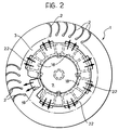
- Figure 2 is a front view of the fan taken on the arrow II of Figure 1, and
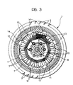
- Figure 3 is a cross-section of the driven fan taken on the line III-III of Figure 1.
- With reference to the drawings, a fan according to the invention includes a bladed, centrifugal fan wheel 1 with a circular array of
frontal blades 2 fixed integrally to a cup-shaped hub 3 (Figure 1). The fan wheel 1 may conveniently be moulded from plastics material. - The fan wheel is keyed to the
shaft 4 of an electric drive motor generally indicated 5. In the embodiment shown by way of example, the motor is a brushless motor with an external rotor. The motor includes a casing constituted by astationary part 6, for example, also moulded from plastics material, and ametal shell 7, for example, of iron. The shell, which is also substantially cup-shaped, is fixed torsionally to thehub 3 of the bladed fan wheel 1. In the embodiment shown, this is achieved by the upsetting of the ends of integralinternal projections 3a of thehub 3 which extend through holes provided for the purpose in the shell 7 (Figure 1). - The unit constituted by the
shell 7 and the bladed fan wheel 1 is keyed to one end of theshaft 4 of the electric motor, the shaft being rotatable inbearings 8 mounted in a centraltubular portion 9a of a shaped support member 9, for example, of aluminium, fixed to thestationary cover 6 byscrews 10. - The stator structure of the electric motor, comprising a pack of
plates 10 carrying thestator windings 11, is fixed around thetubular portion 9a of the support member 9. - A
support plate 12 is mounted between aflange portion 9b of the support member 9 and the stationary outer cover 6 (Figure 1) and carries the components of an electronic circuit for controlling the motor. - The
flange portion 9b of the support member 9 has a plurality of cooling fins, indicated 9c. - The
shell 7 houses angularly-spaced permanent magnets, indicated 13 in Figures 1 and 3. As can be seen in particular in Figure 3, the permanent magnets are spaced equiangularly and a space or gap, indicated 14, is defined between each pair of magnets. - The
permanent magnets 13 are disposed around the stator structure of the electric motor, as can be seen particularly in Figure 1. - A hole (indicated 16 in Figure 1) is defined in the
stationary part 6 of the casing of the electric motor 5 for taking in air from the outside atmosphere (in the direction of the arrow F in Figure 1) for ventilating the interior of the electric motor 5. - In the embodiment shown by way of example, the
shell 7 of the motor has a plurality of equiangularly-spaced holes 18 (Figures 1 and 2). These holes face corresponding radial channels 19 (Figure 1) defined in the concave face of thehub 3 of the fan wheel between anannular projection 20 of the hub and a radiallyoutermost part 21 of the hub facing the blades. Thechannels 19 open to the outside throughholes 22 in the hub. - As can be seen in Figure 2, the
holes 18 in theshell 7 of the motor, thechannels 19 and theholes 22 in the hub of the fan wheel together define a series of outlet ducts for the air which ventilates the interior of the motor. Conveniently, as can be seen in particular in Figure 1, these outlet ducts are formed so that their cross-sections decrease in the direction in which the internal ventilation air flows out so as to achieve a kind of Venturi effect. - As can be seen particularly in Figure 1, the
holes 22 through which the internal ventilation air can flow are formed in a region of thehub 3 of the fan wheel over which the centrifugal air-flow induced by the fan wheel flows in operation. - Within the electric motor 5, the air drawn in through the
intake hole 16 in operation flows over the components of the control circuit carried by theplate 12 and theflange portion 9a of the support structure 9 and then reaches the pack ofstator plates 10, thewindings 11, and thepermanent magnets 13, passing throughholes 23 in theflange portion 9a of the support structure 9. - Some of the air for ventilating the interior of the motor flows through the
spaces 14 between adjacent pairs ofpermanent magnets 13. Conveniently, theholes 18 in the half-shell 7 and thechannels 19 in thehub 3 of the fan wheel are formed in angular positions corresponding to those of thespaces 14 between the magnets. - In operation, the ventilation of the interior of the electric motor 5 is particularly effective because of the extraction effect induced both by the shapes of the air-outlet ducts 18-22 and by the suction effect induced by the air-flow generated by the
fan 2, which produces fast-flowing streams of fluid over theoutlet holes 22. - Naturally, the principle of the invention remaining the same, the forms of embodiment and details of construction may be varied widely with respect to those described and illustrated purely by way of non-limiting example, without thereby departing from the scope of the present invention.
- The shapes and arrangement of the outlet ducts for the internal ventilation air give very good results not only in a brushless motor, as in the embodiment described above, but also in general in the direct-current motors with commutators conventionally used in motor vehicle fans.
Claims (5)
- A fan, particularly for motor vehicles, comprising:
a bladed, centrifugal fan wheel (1-3), and
an electric drive motor (5) with an external rotor (7, 13) which is fixed torsionally to the fan wheel (3), the motor including a casing (6, 7) comprising a stationary part (6) with at least one hole (16) for taking in air from the outside atmosphere for ventilating the interior of the motor (5) and a rotary part (7, 3) with at least one hole (18-22) which acts as an outlet duct for the internal ventilation air,
characterised in that the at least one hole (18-22) in the rotary part (3, 7) of the casing of the motor (5) is constituted by a duct whose cross-section decreases in the direction in which the internal ventilation air flows out, and in that the duct (18-22) is formed so as to open into the outside atmosphere in a region (21) over which the air-flow induced by the fan wheel (1-3) passes in operation. - A fan according to Claim 1, in which the electric motor (5) is of the brushless type and has angularly spaced permanent magnets (13) within the rotary part (7, 3) of the casing (3, 6, 7) of the motor (5),
characterised in that the permanent magnets (13) are separated by spaces or gaps (14) through which at least some of the air-flow for the internal ventilation of the motor (5) can pass. - A fan according to Claim 2, characterised in that the rotary portion (3, 7) of the casing of the motor (5) has a plurality of outlet holes (22) for the internal ventilation air in relative positions corresponding to the relative angular positions of the spaces (14) between the permanent magnets (13).
- A fan according to Claim 2 or Claim 3, characterised in that the stationary part (6) of the motor (5) includes a plate (12) for supporting the components of a control circuit for the motor (5), the plate extending transverse the axis of rotation of the motor (5) between the at least one intake hole (16) and the at least one outlet hole (22) for the internal ventilation air.
- A fan according to Claim 4, characterised in that the stationary part of the electric motor (5) includes a metal support member (9) with a series of cooling fins ( 9c).
Applications Claiming Priority (2)
| Application Number | Priority Date | Filing Date | Title |
|---|---|---|---|
| IT6784990 | 1990-10-30 | ||
| IT67849A IT1240997B (en) | 1990-10-30 | 1990-10-30 | MOTOR FAN, PARTICULARLY FOR MOTOR VEHICLES |
Publications (2)
| Publication Number | Publication Date |
|---|---|
| EP0488961A1 true EP0488961A1 (en) | 1992-06-03 |
| EP0488961B1 EP0488961B1 (en) | 1994-05-25 |
Family
ID=11305764
Family Applications (1)
| Application Number | Title | Priority Date | Filing Date |
|---|---|---|---|
| EP91830447A Expired - Lifetime EP0488961B1 (en) | 1990-10-30 | 1991-10-22 | A fan, particularly for motor vehicles |
Country Status (5)
| Country | Link |
|---|---|
| US (1) | US5217353A (en) |
| EP (1) | EP0488961B1 (en) |
| DE (1) | DE69102127T2 (en) |
| ES (1) | ES2053312T3 (en) |
| IT (1) | IT1240997B (en) |
Cited By (12)
| Publication number | Priority date | Publication date | Assignee | Title |
|---|---|---|---|---|
| EP0645542A1 (en) * | 1993-09-24 | 1995-03-29 | Ecia - Equipements Et Composants Pour L'industrie Automobile | Automobile engine fan and hub |
| DE4440495A1 (en) * | 1994-11-12 | 1996-05-15 | Bosch Gmbh Robert | Electrically operated air-blower unit as unit e.g. for blowing secondary air into IC engine exhaust system |
| EP0762051A3 (en) * | 1993-12-06 | 1997-04-02 | Papst-Motoren Gmbh & Co. Kg | Blower for gas premix burner |
| EP0780579A1 (en) * | 1995-12-20 | 1997-06-25 | TEMIC Automotive Electric Motors GmbH | Radial blower, particularly for heating- and airconditioning systems of motor vehicles |
| EP0805276A3 (en) * | 1996-04-30 | 1999-05-19 | Itt Automotive Electrical Systems, Inc. | Blower assembly having integral air flow cooling duct |
| FR2776140A1 (en) * | 1998-03-16 | 1999-09-17 | Asmo Co Ltd | Brushless electrical motor for an automobile air conditioning fan |
| WO1999060277A1 (en) * | 1998-05-15 | 1999-11-25 | Robert Bosch Gmbh | Fan |
| US7282823B2 (en) * | 2004-10-29 | 2007-10-16 | Emerson Electric Co. | Self-cooling electric machine |
| EP2211444A3 (en) * | 2009-01-27 | 2010-12-15 | ebm-papst Mulfingen GmbH & Co. KG | Electric motor with cooling ventilator effect |
| ITPD20090377A1 (en) * | 2009-12-18 | 2011-06-19 | Sit La Precisa S P A Con Socio Uni Co | ELECTRONIC BOARD FOR THE MANAGEMENT OF A BOILER WITH A PRE-MIXING BURNER, IN PARTICULAR FOR CONDENSING PRE-MIXED BURNERS. |
| FR3050490A1 (en) * | 2016-04-26 | 2017-10-27 | Valeo Systemes Thermiques | PULSEUR FOR A HEATING, VENTILATION AND / OR AIR CONDITIONING SYSTEM |
| WO2021245079A1 (en) * | 2020-06-01 | 2021-12-09 | Valeo Systemes Thermiques | Motor rotor, in particular for a fan motor of a motor vehicle heating, ventilation and/or air conditioning system |
Families Citing this family (29)
| Publication number | Priority date | Publication date | Assignee | Title |
|---|---|---|---|---|
| DE4341564A1 (en) * | 1993-12-07 | 1995-06-08 | Bosch Gmbh Robert | Unit for feeding fuel from tank to IC engine |
| IT1273198B (en) * | 1994-05-12 | 1997-07-07 | Bitron A Spa | IMPROVEMENTS TO AN ELECTRONICALLY COMMUTED FAN FOR THE CABIN OF A VEHICLE |
| DE4418000C2 (en) † | 1994-05-21 | 1998-03-19 | Fhp Motors Gmbh | Electronically controlled electric motor, in particular with a fan wheel for sucking in cooling air for motor vehicles |
| US5638796A (en) * | 1994-06-03 | 1997-06-17 | Adams, Iii; Herbert L. | Electric supercharger |
| IT1279098B1 (en) * | 1995-01-10 | 1997-12-04 | Bitron Spa | IMPROVEMENTS TO BRUSHLESS MOTORS, IN PARTICULAR FOR DIRECT DRIVING OF THE WASHING MACHINE BASKET |
| US5967764A (en) * | 1997-08-08 | 1999-10-19 | Bosch Automotive Systems Corporation | Axial fan with self-cooled motor |
| US5944497A (en) * | 1997-11-25 | 1999-08-31 | Siemens Canada Limited | Fan assembly having an air directing member to cool a motor |
| US6227822B1 (en) * | 1998-10-20 | 2001-05-08 | Lakewood Engineering And Manufacturing Co. | Fan with improved electric motor and mounting |
| IT1308475B1 (en) * | 1999-05-07 | 2001-12-17 | Gate Spa | FAN MOTOR, IN PARTICULAR FOR A HEAT EXCHANGER OF A VEHICLE |
| FR2795458B1 (en) * | 1999-06-24 | 2002-06-14 | Jeumont Ind | MOTOR FAN FOR CIRCULATING A FLUID IN A HEAT EXCHANGE INSTALLATION AND METHOD FOR COOLING THE MOTOR DRIVE OF THE MOTOR FAN |
| GB2355598B (en) * | 1999-10-08 | 2004-06-02 | Nmb | An external rotor brushless DC motor |
| JP3752594B2 (en) * | 2000-04-25 | 2006-03-08 | 愛三工業株式会社 | Magnetic coupling pump |
| US6461124B1 (en) * | 2000-12-14 | 2002-10-08 | Ametek, Inc. | Through-flow blower with cooling fan |
| AU2003225110A1 (en) * | 2002-04-22 | 2003-11-03 | Tyco Healthcare Group, Lp | Endoscopic surgical clip |
| US7501433B2 (en) * | 2002-05-17 | 2009-03-10 | Jenken Biosciences, Inc. | Opioid and opioid-like compounds and uses thereof |
| JP2004260902A (en) * | 2003-02-25 | 2004-09-16 | Kokusan Denki Co Ltd | Magnetogenerator |
| US8017622B2 (en) | 2003-05-16 | 2011-09-13 | Jenken Biosciences, Inc. | Opioid and opioid-like compounds and uses thereof |
| KR20050099352A (en) * | 2004-04-09 | 2005-10-13 | 엘지전자 주식회사 | Front suction/discharge type outdoor unit for air conditioner |
| US7616440B2 (en) * | 2004-04-19 | 2009-11-10 | Hewlett-Packard Development Company, L.P. | Fan unit and methods of forming same |
| US7554228B2 (en) * | 2005-05-25 | 2009-06-30 | Hewlett-Packard Development Company, L.P. | Cooling fan with an outer rotor motor |
| US20080089798A1 (en) * | 2006-10-17 | 2008-04-17 | Lasko Holdings, Inc. | Box fan grill with integral motor support |
| ITBO20070776A1 (en) * | 2007-11-23 | 2009-05-24 | Spal Automotive Srl | VENTILATION UNIT IN PARTICULAR FOR MOTOR VEHICLES. |
| DE102010012392A1 (en) * | 2010-03-22 | 2011-09-22 | Ebm-Papst Mulfingen Gmbh & Co. Kg | fan |
| DE102010031303A1 (en) * | 2010-07-14 | 2012-01-19 | Robert Bosch Gmbh | fan module |
| US8267673B1 (en) | 2011-05-04 | 2012-09-18 | John Pairaktaridis | Brushless cooling fan |
| CN108626146B (en) * | 2017-03-17 | 2020-05-22 | 日本电产株式会社 | Air supply device and dust collector |
| CN107588043A (en) * | 2017-10-20 | 2018-01-16 | 东风博泽汽车系统有限公司 | A kind of electric motor fan radiating hub structure and its cooling fan formed |
| JP6651491B2 (en) * | 2017-11-27 | 2020-02-19 | シナノケンシ株式会社 | Blower |
| DE102020100865A1 (en) * | 2020-01-16 | 2021-07-22 | Ebm-Papst Mulfingen Gmbh & Co. Kg | Fan with an external rotor motor and cooling duct for cooling the motor electronics and motor drive components |
Citations (4)
| Publication number | Priority date | Publication date | Assignee | Title |
|---|---|---|---|---|
| DE2742962A1 (en) * | 1977-09-23 | 1979-04-05 | Siemens Ag | Centrifugal fan for vacuum cleaner - has permanent magnet DC motor with magnet coupled to impeller |
| US4428719A (en) * | 1980-05-14 | 1984-01-31 | Hitachi, Ltd. | Brushless motor fan |
| EP0345796A2 (en) * | 1988-06-04 | 1989-12-13 | Licentia Patent-Verwaltungs-GmbH | Ventilator driven by an electric motor |
| DE3917040A1 (en) * | 1988-06-02 | 1989-12-14 | Gen Electric | ELECTRONICALLY COMMUTED MOTOR, THEREFORE INTEGRATED BLOWER AND STATIONARY AND ROTATABLE ARRANGEMENTS THEREFOR |
Family Cites Families (11)
| Publication number | Priority date | Publication date | Assignee | Title |
|---|---|---|---|---|
| US2871791A (en) * | 1959-02-03 | litzenberg | ||
| US1230206A (en) * | 1911-04-27 | 1917-06-19 | Richmond Radiator Company | Suction-producer. |
| US1779657A (en) * | 1929-05-03 | 1930-10-28 | Ilg Electric Ventilating Compa | Self-cooled electric motor |
| US3933416A (en) * | 1945-05-01 | 1976-01-20 | Donelian Khatchik O | Hermatically sealed motor blower unit with stator inside hollow armature |
| US2709035A (en) * | 1950-11-13 | 1955-05-24 | Gilbert Co A C | Air streaming fan |
| US2956731A (en) * | 1957-04-29 | 1960-10-18 | Borg Warner | Axial flow fans |
| US3263908A (en) * | 1964-05-15 | 1966-08-02 | Nat Union Electric Corp | Cooling arrangement for a vacuum cleaner motor or the like |
| US3341113A (en) * | 1965-10-21 | 1967-09-12 | Ametek Inc | Fluid moving system and an electric motor-pump unit therefor |
| US3698839A (en) * | 1970-10-14 | 1972-10-17 | Borg Warner | Pressure equalizer for unloading a compressor during start-up |
| JPS58100461U (en) * | 1981-12-26 | 1983-07-08 | 三菱電機株式会社 | Bearing cooling mechanism for vehicle alternator |
| US4527960A (en) * | 1984-02-03 | 1985-07-09 | General Signal Corporation | Bearing air seal for vacuum cleaner motor |
-
1990
- 1990-10-30 IT IT67849A patent/IT1240997B/en active IP Right Grant
-
1991
- 1991-10-22 DE DE69102127T patent/DE69102127T2/en not_active Expired - Fee Related
- 1991-10-22 EP EP91830447A patent/EP0488961B1/en not_active Expired - Lifetime
- 1991-10-22 ES ES91830447T patent/ES2053312T3/en not_active Expired - Lifetime
- 1991-10-23 US US07/780,638 patent/US5217353A/en not_active Expired - Fee Related
Patent Citations (4)
| Publication number | Priority date | Publication date | Assignee | Title |
|---|---|---|---|---|
| DE2742962A1 (en) * | 1977-09-23 | 1979-04-05 | Siemens Ag | Centrifugal fan for vacuum cleaner - has permanent magnet DC motor with magnet coupled to impeller |
| US4428719A (en) * | 1980-05-14 | 1984-01-31 | Hitachi, Ltd. | Brushless motor fan |
| DE3917040A1 (en) * | 1988-06-02 | 1989-12-14 | Gen Electric | ELECTRONICALLY COMMUTED MOTOR, THEREFORE INTEGRATED BLOWER AND STATIONARY AND ROTATABLE ARRANGEMENTS THEREFOR |
| EP0345796A2 (en) * | 1988-06-04 | 1989-12-13 | Licentia Patent-Verwaltungs-GmbH | Ventilator driven by an electric motor |
Cited By (14)
| Publication number | Priority date | Publication date | Assignee | Title |
|---|---|---|---|---|
| EP0645542A1 (en) * | 1993-09-24 | 1995-03-29 | Ecia - Equipements Et Composants Pour L'industrie Automobile | Automobile engine fan and hub |
| FR2710371A1 (en) * | 1993-09-24 | 1995-03-31 | Ecia Equip Composants Ind Auto | Fan group with improved hub. |
| EP0762051A3 (en) * | 1993-12-06 | 1997-04-02 | Papst-Motoren Gmbh & Co. Kg | Blower for gas premix burner |
| DE4440495A1 (en) * | 1994-11-12 | 1996-05-15 | Bosch Gmbh Robert | Electrically operated air-blower unit as unit e.g. for blowing secondary air into IC engine exhaust system |
| EP0780579A1 (en) * | 1995-12-20 | 1997-06-25 | TEMIC Automotive Electric Motors GmbH | Radial blower, particularly for heating- and airconditioning systems of motor vehicles |
| EP0805276A3 (en) * | 1996-04-30 | 1999-05-19 | Itt Automotive Electrical Systems, Inc. | Blower assembly having integral air flow cooling duct |
| FR2776140A1 (en) * | 1998-03-16 | 1999-09-17 | Asmo Co Ltd | Brushless electrical motor for an automobile air conditioning fan |
| WO1999060277A1 (en) * | 1998-05-15 | 1999-11-25 | Robert Bosch Gmbh | Fan |
| US7282823B2 (en) * | 2004-10-29 | 2007-10-16 | Emerson Electric Co. | Self-cooling electric machine |
| EP2211444A3 (en) * | 2009-01-27 | 2010-12-15 | ebm-papst Mulfingen GmbH & Co. KG | Electric motor with cooling ventilator effect |
| US8217540B2 (en) | 2009-01-27 | 2012-07-10 | Ebm-Papst Mulfingen Gmbh & Co. Kg | Electric motor with cooling ventilator effect |
| ITPD20090377A1 (en) * | 2009-12-18 | 2011-06-19 | Sit La Precisa S P A Con Socio Uni Co | ELECTRONIC BOARD FOR THE MANAGEMENT OF A BOILER WITH A PRE-MIXING BURNER, IN PARTICULAR FOR CONDENSING PRE-MIXED BURNERS. |
| FR3050490A1 (en) * | 2016-04-26 | 2017-10-27 | Valeo Systemes Thermiques | PULSEUR FOR A HEATING, VENTILATION AND / OR AIR CONDITIONING SYSTEM |
| WO2021245079A1 (en) * | 2020-06-01 | 2021-12-09 | Valeo Systemes Thermiques | Motor rotor, in particular for a fan motor of a motor vehicle heating, ventilation and/or air conditioning system |
Also Published As
| Publication number | Publication date |
|---|---|
| ES2053312T3 (en) | 1994-07-16 |
| IT1240997B (en) | 1993-12-27 |
| IT9067849A1 (en) | 1992-04-30 |
| DE69102127T2 (en) | 1995-01-12 |
| EP0488961B1 (en) | 1994-05-25 |
| DE69102127D1 (en) | 1994-06-30 |
| IT9067849A0 (en) | 1990-10-30 |
| US5217353A (en) | 1993-06-08 |
Similar Documents
| Publication | Publication Date | Title |
|---|---|---|
| EP0488961B1 (en) | A fan, particularly for motor vehicles | |
| US8251676B2 (en) | Axial-flow fan for a vehicle radiator | |
| US6283726B1 (en) | Radial blower, particularly for heating and air conditioning systems in automobiles | |
| EP0921318B1 (en) | Fan assembly having motor cooling enhancement | |
| US4766337A (en) | Open drip-proof machinery cooling system using totally enclosed type bearing brackets | |
| CN101317010B (en) | Cooling fans for motor vehicles | |
| US4074156A (en) | Air cooling means for dynamoelectric machine | |
| JP6678302B2 (en) | Temperature control unit, temperature control system, vehicle | |
| CN100431242C (en) | Motor rotor ventilation | |
| JP3704016B2 (en) | Electric blower | |
| RU2003115447A (en) | VENTILATION OF A ROTOR OF A DYNAMOELECTRIC MACHINE | |
| JP4183814B2 (en) | Cage electric motor | |
| JP2006217748A (en) | Fan motor | |
| US3848145A (en) | Electric motor ventilation | |
| JP3581301B2 (en) | Electric blower | |
| GB2225490A (en) | An alternator with two forced ventilation fans, particularly for motor vehicles | |
| CN216981684U (en) | Self-cooling magnetic suspension high-speed motor with heat dissipation impeller | |
| US20200036262A1 (en) | Electric motor having improved motor cooling for driving a fan | |
| JPH06294393A (en) | Blower | |
| JPH04311700A (en) | Motor fan | |
| JPH0779542A (en) | Air cooling structure for salient pole electric rotating machine | |
| JPS5836208Y2 (en) | Rotating electric machine with multi-blade fan | |
| KR20070100525A (en) | Blower and air conditioner having the blower | |
| JPH07117078B2 (en) | Motor fan | |
| JP2650384B2 (en) | Electric motor |
Legal Events
| Date | Code | Title | Description |
|---|---|---|---|
| PUAI | Public reference made under article 153(3) epc to a published international application that has entered the european phase |
Free format text: ORIGINAL CODE: 0009012 |
|
| AK | Designated contracting states |
Kind code of ref document: A1 Designated state(s): DE ES FR GB SE |
|
| 17P | Request for examination filed |
Effective date: 19920725 |
|
| 17Q | First examination report despatched |
Effective date: 19930714 |
|
| GRAA | (expected) grant |
Free format text: ORIGINAL CODE: 0009210 |
|
| AK | Designated contracting states |
Kind code of ref document: B1 Designated state(s): DE ES FR GB SE |
|
| REF | Corresponds to: |
Ref document number: 69102127 Country of ref document: DE Date of ref document: 19940630 |
|
| REG | Reference to a national code |
Ref country code: ES Ref legal event code: FG2A Ref document number: 2053312 Country of ref document: ES Kind code of ref document: T3 |
|
| ET | Fr: translation filed | ||
| EAL | Se: european patent in force in sweden |
Ref document number: 91830447.8 |
|
| PLBE | No opposition filed within time limit |
Free format text: ORIGINAL CODE: 0009261 |
|
| STAA | Information on the status of an ep patent application or granted ep patent |
Free format text: STATUS: NO OPPOSITION FILED WITHIN TIME LIMIT |
|
| 26N | No opposition filed | ||
| REG | Reference to a national code |
Ref country code: GB Ref legal event code: IF02 |
|
| PGFP | Annual fee paid to national office [announced via postgrant information from national office to epo] |
Ref country code: SE Payment date: 20030828 Year of fee payment: 13 |
|
| PGFP | Annual fee paid to national office [announced via postgrant information from national office to epo] |
Ref country code: ES Payment date: 20030901 Year of fee payment: 13 |
|
| PGFP | Annual fee paid to national office [announced via postgrant information from national office to epo] |
Ref country code: GB Payment date: 20030916 Year of fee payment: 13 |
|
| PGFP | Annual fee paid to national office [announced via postgrant information from national office to epo] |
Ref country code: DE Payment date: 20030924 Year of fee payment: 13 |
|
| PGFP | Annual fee paid to national office [announced via postgrant information from national office to epo] |
Ref country code: FR Payment date: 20031030 Year of fee payment: 13 |
|
| PG25 | Lapsed in a contracting state [announced via postgrant information from national office to epo] |
Ref country code: GB Free format text: LAPSE BECAUSE OF NON-PAYMENT OF DUE FEES Effective date: 20041022 |
|
| PG25 | Lapsed in a contracting state [announced via postgrant information from national office to epo] |
Ref country code: SE Free format text: LAPSE BECAUSE OF NON-PAYMENT OF DUE FEES Effective date: 20041023 Ref country code: ES Free format text: LAPSE BECAUSE OF NON-PAYMENT OF DUE FEES Effective date: 20041023 |
|
| PG25 | Lapsed in a contracting state [announced via postgrant information from national office to epo] |
Ref country code: DE Free format text: LAPSE BECAUSE OF NON-PAYMENT OF DUE FEES Effective date: 20050503 |
|
| EUG | Se: european patent has lapsed | ||
| GBPC | Gb: european patent ceased through non-payment of renewal fee |
Effective date: 20041022 |
|
| PG25 | Lapsed in a contracting state [announced via postgrant information from national office to epo] |
Ref country code: FR Free format text: LAPSE BECAUSE OF NON-PAYMENT OF DUE FEES Effective date: 20050630 |
|
| REG | Reference to a national code |
Ref country code: FR Ref legal event code: ST |
|
| REG | Reference to a national code |
Ref country code: ES Ref legal event code: FD2A Effective date: 20041023 |