EP0488652A2 - An image forming apparatus - Google Patents
An image forming apparatus Download PDFInfo
- Publication number
- EP0488652A2 EP0488652A2 EP91310885A EP91310885A EP0488652A2 EP 0488652 A2 EP0488652 A2 EP 0488652A2 EP 91310885 A EP91310885 A EP 91310885A EP 91310885 A EP91310885 A EP 91310885A EP 0488652 A2 EP0488652 A2 EP 0488652A2
- Authority
- EP
- European Patent Office
- Prior art keywords
- toner
- image forming
- passages
- forming apparatus
- substrate
- Prior art date
- Legal status (The legal status is an assumption and is not a legal conclusion. Google has not performed a legal analysis and makes no representation as to the accuracy of the status listed.)
- Granted
Links
Images

Classifications
-
- G—PHYSICS
- G03—PHOTOGRAPHY; CINEMATOGRAPHY; ANALOGOUS TECHNIQUES USING WAVES OTHER THAN OPTICAL WAVES; ELECTROGRAPHY; HOLOGRAPHY
- G03G—ELECTROGRAPHY; ELECTROPHOTOGRAPHY; MAGNETOGRAPHY
- G03G15/00—Apparatus for electrographic processes using a charge pattern
- G03G15/22—Apparatus for electrographic processes using a charge pattern involving the combination of more than one step according to groups G03G13/02 - G03G13/20
- G03G15/34—Apparatus for electrographic processes using a charge pattern involving the combination of more than one step according to groups G03G13/02 - G03G13/20 in which the powder image is formed directly on the recording material, e.g. by using a liquid toner
- G03G15/344—Apparatus for electrographic processes using a charge pattern involving the combination of more than one step according to groups G03G13/02 - G03G13/20 in which the powder image is formed directly on the recording material, e.g. by using a liquid toner by selectively transferring the powder to the recording medium, e.g. by using a LED array
- G03G15/346—Apparatus for electrographic processes using a charge pattern involving the combination of more than one step according to groups G03G13/02 - G03G13/20 in which the powder image is formed directly on the recording material, e.g. by using a liquid toner by selectively transferring the powder to the recording medium, e.g. by using a LED array by modulating the powder through holes or a slit
-
- B—PERFORMING OPERATIONS; TRANSPORTING
- B41—PRINTING; LINING MACHINES; TYPEWRITERS; STAMPS
- B41J—TYPEWRITERS; SELECTIVE PRINTING MECHANISMS, i.e. MECHANISMS PRINTING OTHERWISE THAN FROM A FORME; CORRECTION OF TYPOGRAPHICAL ERRORS
- B41J2/00—Typewriters or selective printing mechanisms characterised by the printing or marking process for which they are designed
- B41J2/385—Typewriters or selective printing mechanisms characterised by the printing or marking process for which they are designed characterised by selective supply of electric current or selective application of magnetism to a printing or impression-transfer material
- B41J2/41—Typewriters or selective printing mechanisms characterised by the printing or marking process for which they are designed characterised by selective supply of electric current or selective application of magnetism to a printing or impression-transfer material for electrostatic printing
- B41J2/415—Typewriters or selective printing mechanisms characterised by the printing or marking process for which they are designed characterised by selective supply of electric current or selective application of magnetism to a printing or impression-transfer material for electrostatic printing by passing charged particles through a hole or a slit
- B41J2/4155—Typewriters or selective printing mechanisms characterised by the printing or marking process for which they are designed characterised by selective supply of electric current or selective application of magnetism to a printing or impression-transfer material for electrostatic printing by passing charged particles through a hole or a slit for direct electrostatic printing [DEP]
-
- G—PHYSICS
- G03—PHOTOGRAPHY; CINEMATOGRAPHY; ANALOGOUS TECHNIQUES USING WAVES OTHER THAN OPTICAL WAVES; ELECTROGRAPHY; HOLOGRAPHY
- G03G—ELECTROGRAPHY; ELECTROPHOTOGRAPHY; MAGNETOGRAPHY
- G03G2217/00—Details of electrographic processes using patterns other than charge patterns
- G03G2217/0008—Process where toner image is produced by controlling which part of the toner should move to the image- carrying member
- G03G2217/0025—Process where toner image is produced by controlling which part of the toner should move to the image- carrying member where the toner starts moving from behind the electrode array, e.g. a mask of holes
Definitions
- the present invention relates to an image forming apparatus using powder toner.
- the ink-jet printer is a typical example of a nonimpact printer, where pressure is applied to a prescribed liquid ink while a piezoelectric element or the like applies ultrasonic vibration thereto, so that the liquid ink is spurted from an ink nozzle into a prescribed electric field.
- the ink particles are controlled by the electric field and made to adhere to a recording sheet to form an image thereon.
- Such an ink-jet printing has the advantage of being able to form a clear image without generating noise during the formation of the image.
- this method is disadvantageous in that it requires the use of a special kind of recording sheet with its surface appropriately treated so as to control the rate at which the ink filters into the recording sheet. Further, the nozzle through which the ink is supplied tends to become clogged with foreign substances or the like contained in the ink.
- Japanese Laid-Open Patent Publication No. 60-263962 discloses an image forming apparatus using powder toner as an image forming medium.
- This image forming apparatus is equipped with a toner control means which controls the passing of toner particles through a toner passage in the form of a pinhole by an electrostatic attraction generated in accordance with image output signals.
- the toner control means the toner particles are selectively fed onto a recording sheet, thereby forming a prescribed image on the recording sheet.
- a sheet of plane paper without surface treatment can be used as the recording sheet. Further, since the powder toner in the form of fine particles is used, the toner passage is prevented from becoming clogged with the toner.
- the toner control means comprises an insulating substrate with a number of pinhole-shaped toner passages formed therethrough and a pair of electrodes sandwiching the insulating substrate so that an electric field is formed inside each of the toner passages.
- the pair of electrodes also have holes extending therethrough, respectively, each having the same size as that of the toner passage.
- the electrodes are disposed on the opposite surfaces of the insulating substrate, respectively, in such a manner that each hole is aligned with the corresponding toner passage.
- a prescribed voltage is applied between the pair of electrodes to form an electric field in a prescribed direction inside each toner passage, thereby allowing toner particles to pass through the toner passage.
- an electric field in the direction opposite to the above direction can be formed by applying a prescribed voltage between the electrodes.
- a base electrode is disposed downstream in the toner passing direction with respect to the toner control means (on the recording sheet supply side).
- the recording sheet is placed on the base electrode.
- a prescribed potential difference is produced between the base electrode and the electrode disposed on the toner feed side of the toner control means to form an electric field therebetween, so as to ensure that the toner moves toward the recording sheet.
- a dot is formed by the toner which has passed through each toner passage, and a group of dots form an image such as a letter.
- the toner passages are generally disposed in a line perpendicular to the direction of the conveyance of the recording sheet.
- a voltage signal as a control signal is input to the pair of electrodes of the toner control means to control the formation of the image.
- a fixed amount of toner is fed onto one electrode disposed on the insulating substrate by means of a toner feed roller.
- the toner feed roller may be in contact with or in close proximity to the electrode.
- the toner is present on the electrode not only when an image is formed but also when an image is not formed.
- the toner may enter the toner passages when an image is not formed, thereby causing clogging of the toner passages.
- the objective of this invention is to solve the above-described prior art problem and to provide an image forming apparatus in which toner does not enter into the toner passages when an image is not formed so as to prevent the toner passages from clogging with the toner.
- the image forming apparatus of this invention which overcomes the above-discussed and numerous other disadvantages and deficiencies of the prior art, comprises a substrate having a plurality of toner passages extending therethrough, a pair of electrodes, each having holes extending therethrough and communicating with the corresponding toner passages of the substrate, the electrodes sandwiching the substrate as an insulation and being disposed so that each hole of each electrode is aligned with the corresponding toner passage, a toner feed means disposed above one electrode for feeding charged toner, a shifting means for moving the toner feed means toward or away from the toner passages in the substrate, and an image information generating means for giving a prescribed potential between the pair of electrodes so that an electric field which causes the charged toner to pass through the toner passages is formed inside the toner passages.
- the shifting means moves the toner feed means toward or away from the substrate.
- the shifting means moves the toner feed means along the substrate.
- a nozzle section is further provided which faces the toner passages when the toner feed means is moved away from the toner passages of the substrate by the shifting means, so that air is spurted out from the nozzle section.
- a plurality of toner feed means are disposed rotatably around a support axis, so that each of the toner feed means faces the toner passages of the substrate as they rotate.
- toner feed means are provided for feeding magenta, cyan, yellow, and black toners, respectively.
- an image forming operation is performed only when the toner feed roller faces the toner passage of the substrate.
- the toner fed on one electrode by the toner feed means passes through the toner passages of the substrate in accordance with image signals sent from the image information generating means.
- the toner feed means is moved away from the toner passage by the shifting means, preventing the toner from falling into the toner passage.
- the present invention makes possible the objective of providing an image forming apparatus which is free from clogging of the toner passage with the toner.
- an image forming apparatus of the present invention comprises an insulating substrate 30 having a number of toner passages 31 in the form of pinholes punctured in a line.
- a common electrode 50 having a number of holes 51 vertically extending therethrough. Each hole 51 has the same size as that of the toner passage 31 .
- the common electrode 50 is mounted on the insulating substrate 30 so that each hole 51 is aligned with the corresponding toner passage 31 .
- signal electrodes 60 On the bottom surface of the insulating substrate 30 is disposed signal electrodes 60 each having a hole 61 of the same size as that of the toner passage 31 . Each signal electrode encircles the bottom opening of the corresponding toner passage 31 , and the hole 61 is aligned with the toner passage 31 . The two signal electrodes 60 placed around the adjacent toner passages 31 are not in contact with each other.
- the common electrode 50 is grounded.
- the signal electrodes 60 are connected to an image information generating unit 70 , from which electric signals are sent to each of the signal electrodes 60 .
- the image information generating unit 70 operates in response to signals sent from a machine body such as a word processor, a facsimile machine, or a computer and generates electric signals in accordance with the image information.
- Each of the signal electrodes 60 receive a prescribed potential in accordance with the image information; for example, when non-image forming information is to be sent, a prescribed negative potential is applied to the signal electrode 60 , and when image forming information is to be sent, a prescribed positive potential is applied to the signal electrode 60 .
- a conveying roller 40 which is made of conductive material, is disposed below the toner passages 31 of the insulating substrate 30 .
- the conveying roller 40 is rotated in a prescribed direction so that a recording sheet 80 is conveyed in the direction shown by arrow A in Figure 1 .
- a prescribed positive potential is applied to the conveying roller 40 .
- a toner container 10 containing powder toner is disposed above the insulating substrate 30 , and has an opening 11 in the lower part thereof.
- the opening 11 accommodates the upper part of a toner feed roller 15 which functions as a toner feed means.
- the toner feed roller 15 which may be a sponge roller faces the line of toner passages 31 formed in the insulating substrate 30 .
- the toner contained in the toner container 10 is continuously fed downward with the rotation of the toner feed roller 15 .
- the toner container 10 is swingably supported on a support axis 12 which is disposed in parallel with the axis of the toner feed roller 15 upstream in the direction of arrow A with respect to the toner container.
- a solenoid 91 is disposed on the opposite side with respect to the toner container 10 (downstream in the direction of arrow A ).
- the solenoid 91 is fixed to an appropriate support plate 92 so that a plunger 91a of the solenoid 91 moves vertically.
- the plunger 91a is urged upward with a compression spring 91b .
- a lever 13 fixed to the toner container 10 is swingably linked to the upper portion of the plunger 91a . Below the lever 13 , a positioning portion 14 is formed for positioning the toner container 10 by abutting against the end portion of the support plate 92 .
- the plunger 91a thereof When the solenoid 91 is not electrified, the plunger 91a thereof is in the upward stretched state by being urged with the compression spring 91b , and thus the toner container is in the state of being swung upward around the support axis 12 . As a result, the toner feed roller 15 accommodated in the lower portion of the toner container 10 is apart from the common electrode 50 disposed on the insulating substrate 30 .
- the plunger 91a moves downward against the compression spring 91b , and thereby the toner container 10 is swung downward until the positioning portion 14 thereof abuts against the support plate 92 . As a result, the toner feed roller 15 comes into contact with or in close proximity to the common electrode 50 .
- the solenoid 91 When an image forming operation is performed, the solenoid 91 is electrified. Then, the plunger 91a moves downward, and thereby the entire body of the toner container 10 is swung downward around the support axis 12 . As a result, the toner feed roller 15 is pressed against or in close proximity to the common electrode 50 . This allows the toner to be fed onto the common electrode 50 .
- the toner fed on the common electrode 50 is controlled by an electric field formed between the common electrode 50 and each of the signal electrodes 60 disposed on the bottom surface of the insulating substrate 30 in accordance with an image signal sent to each of the signal electrodes 60 so as to form an image on the recording sheet 80 conveyed by the conveying roller 40 .
- the image information generating unit 70 applies negative potential to the corresponding signal electrode 60 .
- the negatively charged toner fed on the common electrode 50 does not pass through the corresponding toner passage 31 .
- the image information generating unit 70 applies positive potential to the signal electrode 60 .
- an electric field which allows the negatively charged toner to pass through the toner passage 31 is formed therein. In this way, the negatively charged toner particles are attracted toward the signal electrode 50 , passing through the corresponding hole 51 of the common electrode 50 , the toner passage 31 , and the corresponding hole 61 of the signal electrode 60 .
- the recording sheet 80 is conveyed to a prescribed fixing device (not shown), where the toner image is fixed on the recording sheet 80 .
- FIG 2 shows a second example of an image forming apparatus according to the present invention.
- the toner container 10 is disposed movably along the insulating substrate 30 .
- the entire body of the toner container 10 horizontally moves by means of a cylinder 95 .
- An air flow chamber 96 is disposed downstream in the direction of arrow A with respect to the toner container 10 .
- a fan 97 is disposed on the side wall of the air flow chamber to introduce air into the air flow chamber.
- In the lower portion of the air flow chamber 96 is formed a tapered nozzle section 96a , which faces the insulating substrate 30 .
- the air introduced into the air flow chamber 96 by the fan 97 flows inside the air flow chamber 96 and is spurted out from the nozzle section 96a .
- the nozzle section 96a faces the toner passages 31 of the insulating substrate 30 when the entire body of the toner container 10 is moved in the direction shown by arrow B in Figure 2 (the direction opposite to the recording sheet conveying
- the conveying roller 40 facing the toner passages 31 of the insulating substrate 30 is held in a casing 41 opened upward.
- a blade 42 fixed inside the casing 41 slides with the circumferential surface of the conveying roller 40 .
- the entire body of the toner container 10 is moved in the direction of arrow B by means of the cylinder 95 until the nozzle section 96a of the air flow chamber 96 faces the toner passages 31 of the insulating substrate 30 as shown in Figure 3 .
- the fan 97 is driven for a prescribed period of time so that the air is spurted from the nozzle section 96a to the toner passages 31 .
- This causes the toner present inside the toner passages 31 to pass therethrough to attach on the circumferential surface of the conveying roller 40 located below the toner passages 31 .
- the toner attached is then wiped off down to the inside of the casing 41 by means of the blade 42 when the conveying roller 40 rotates.
- a third example of an image forming apparatus comprises a toner container 20 having a diamond-shaped section, which is composed of four diamond-shaped toner compartments 21 containing magenta, cyan, yellow, and black toners, respectively.
- a toner feed roller 22 is rotatably placed in outward facing corner portion of each toner compartment 21 .
- a support axis 23 is inserted into the core of the toner container 20 and is rotated by a rotating means (not shown).
- Other structures of this image forming apparatus are the same as those of Example 1 .
- the entire body of the toner container 20 is rotated by 45° from the position where either one of the toner feed rollers faces the common electrode 50 , so that none of the toner feed rollers face the common electrode 50 .
Abstract
Description
- The present invention relates to an image forming apparatus using powder toner.
- It is known to employ an image forming method using an ink-jet printer for word processors, facsimile machines, computers, and the like.
- The ink-jet printer is a typical example of a nonimpact printer, where pressure is applied to a prescribed liquid ink while a piezoelectric element or the like applies ultrasonic vibration thereto, so that the liquid ink is spurted from an ink nozzle into a prescribed electric field. The ink particles are controlled by the electric field and made to adhere to a recording sheet to form an image thereon. Such an ink-jet printing has the advantage of being able to form a clear image without generating noise during the formation of the image. On the other hand, this method is disadvantageous in that it requires the use of a special kind of recording sheet with its surface appropriately treated so as to control the rate at which the ink filters into the recording sheet. Further, the nozzle through which the ink is supplied tends to become clogged with foreign substances or the like contained in the ink.
- To overcome the above difficulties with the ink-jet printer, Japanese Laid-Open Patent Publication No. 60-263962, for example, discloses an image forming apparatus using powder toner as an image forming medium. This image forming apparatus is equipped with a toner control means which controls the passing of toner particles through a toner passage in the form of a pinhole by an electrostatic attraction generated in accordance with image output signals. Through this toner control means, the toner particles are selectively fed onto a recording sheet, thereby forming a prescribed image on the recording sheet.
- In such an image forming apparatus, a sheet of plane paper without surface treatment can be used as the recording sheet. Further, since the powder toner in the form of fine particles is used, the toner passage is prevented from becoming clogged with the toner.
- The toner control means comprises an insulating substrate with a number of pinhole-shaped toner passages formed therethrough and a pair of electrodes sandwiching the insulating substrate so that an electric field is formed inside each of the toner passages. The pair of electrodes also have holes extending therethrough, respectively, each having the same size as that of the toner passage. The electrodes are disposed on the opposite surfaces of the insulating substrate, respectively, in such a manner that each hole is aligned with the corresponding toner passage. A prescribed voltage is applied between the pair of electrodes to form an electric field in a prescribed direction inside each toner passage, thereby allowing toner particles to pass through the toner passage. On the contrary, when it is required for toner particles not to pass through the toner passage, an electric field in the direction opposite to the above direction can be formed by applying a prescribed voltage between the electrodes.
- A base electrode is disposed downstream in the toner passing direction with respect to the toner control means (on the recording sheet supply side). The recording sheet is placed on the base electrode. A prescribed potential difference is produced between the base electrode and the electrode disposed on the toner feed side of the toner control means to form an electric field therebetween, so as to ensure that the toner moves toward the recording sheet.
- In the image forming apparatus as described above, a dot is formed by the toner which has passed through each toner passage, and a group of dots form an image such as a letter. The toner passages are generally disposed in a line perpendicular to the direction of the conveyance of the recording sheet. A voltage signal as a control signal is input to the pair of electrodes of the toner control means to control the formation of the image.
- In the above image forming apparatus, a fixed amount of toner is fed onto one electrode disposed on the insulating substrate by means of a toner feed roller. The toner feed roller may be in contact with or in close proximity to the electrode. Thus, the toner is present on the electrode not only when an image is formed but also when an image is not formed. As a result, the toner may enter the toner passages when an image is not formed, thereby causing clogging of the toner passages.
- The objective of this invention is to solve the above-described prior art problem and to provide an image forming apparatus in which toner does not enter into the toner passages when an image is not formed so as to prevent the toner passages from clogging with the toner.
- The image forming apparatus of this invention, which overcomes the above-discussed and numerous other disadvantages and deficiencies of the prior art, comprises a substrate having a plurality of toner passages extending therethrough, a pair of electrodes, each having holes extending therethrough and communicating with the corresponding toner passages of the substrate, the electrodes sandwiching the substrate as an insulation and being disposed so that each hole of each electrode is aligned with the corresponding toner passage, a toner feed means disposed above one electrode for feeding charged toner, a shifting means for moving the toner feed means toward or away from the toner passages in the substrate, and an image information generating means for giving a prescribed potential between the pair of electrodes so that an electric field which causes the charged toner to pass through the toner passages is formed inside the toner passages.
- In a preferred embodiment, the shifting means moves the toner feed means toward or away from the substrate.
- In a preferred embodiment, the shifting means moves the toner feed means along the substrate.
- In a preferred embodiment, a nozzle section is further provided which faces the toner passages when the toner feed means is moved away from the toner passages of the substrate by the shifting means, so that air is spurted out from the nozzle section.
- In a preferred embodiment, a plurality of toner feed means are disposed rotatably around a support axis, so that each of the toner feed means faces the toner passages of the substrate as they rotate.
- In a preferred embodiment, four toner feed means are provided for feeding magenta, cyan, yellow, and black toners, respectively.
- In the image forming apparatus of the present invention, an image forming operation is performed only when the toner feed roller faces the toner passage of the substrate. The toner fed on one electrode by the toner feed means passes through the toner passages of the substrate in accordance with image signals sent from the image information generating means. When an image forming operation is not performed, the toner feed means is moved away from the toner passage by the shifting means, preventing the toner from falling into the toner passage.
- As a result, it is ensured that at an image forming operation the toner is fed to the toner passages and that when an image forming operation is not performed the toner is not fed to the toner passages. Thus, the present invention makes possible the objective of providing an image forming apparatus which is free from clogging of the toner passage with the toner.
- This invention may be better understood and its numerous objects and advantages will become apparent to those skilled in the art by reference to the accompanying drawings as follows:
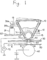
- Figure 1 is a sectional view showing an example of an image forming apparatus according to the present invention;
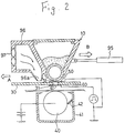
- Figure 2 is a sectional view showing another example of an image forming apparatus according to the present invention;
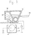
- Figure 3 is a sectional view illustrating the operation of the image forming apparatus of Figure 2; and
- Figure 4 is a sectional view showing still another example of an image forming apparatus according to the present invention.
- Referring to Figure 1, an image forming apparatus of the present invention comprises an
insulating substrate 30 having a number oftoner passages 31 in the form of pinholes punctured in a line. - On the top surface of the
insulating substrate 30 is disposed acommon electrode 50 having a number ofholes 51 vertically extending therethrough. Eachhole 51 has the same size as that of thetoner passage 31. Thecommon electrode 50 is mounted on theinsulating substrate 30 so that eachhole 51 is aligned with thecorresponding toner passage 31. - On the bottom surface of the
insulating substrate 30 is disposedsignal electrodes 60 each having ahole 61 of the same size as that of thetoner passage 31. Each signal electrode encircles the bottom opening of thecorresponding toner passage 31, and thehole 61 is aligned with thetoner passage 31. The twosignal electrodes 60 placed around theadjacent toner passages 31 are not in contact with each other. - The
common electrode 50 is grounded. Thesignal electrodes 60 are connected to an image information generating unit 70, from which electric signals are sent to each of thesignal electrodes 60. The image information generating unit 70 operates in response to signals sent from a machine body such as a word processor, a facsimile machine, or a computer and generates electric signals in accordance with the image information. Each of thesignal electrodes 60 receive a prescribed potential in accordance with the image information; for example, when non-image forming information is to be sent, a prescribed negative potential is applied to thesignal electrode 60, and when image forming information is to be sent, a prescribed positive potential is applied to thesignal electrode 60. - A
conveying roller 40, which is made of conductive material, is disposed below thetoner passages 31 of theinsulating substrate 30. The conveyingroller 40 is rotated in a prescribed direction so that arecording sheet 80 is conveyed in the direction shown by arrow A in Figure 1. A prescribed positive potential is applied to theconveying roller 40. - A
toner container 10 containing powder toner is disposed above theinsulating substrate 30, and has anopening 11 in the lower part thereof. The opening 11 accommodates the upper part of atoner feed roller 15 which functions as a toner feed means. Thetoner feed roller 15 which may be a sponge roller faces the line oftoner passages 31 formed in theinsulating substrate 30. The toner contained in thetoner container 10 is continuously fed downward with the rotation of thetoner feed roller 15. - The
toner container 10 is swingably supported on asupport axis 12 which is disposed in parallel with the axis of thetoner feed roller 15 upstream in the direction of arrow A with respect to the toner container. Asolenoid 91 is disposed on the opposite side with respect to the toner container 10 (downstream in the direction of arrow A). Thesolenoid 91 is fixed to anappropriate support plate 92 so that aplunger 91a of thesolenoid 91 moves vertically. Theplunger 91a is urged upward with acompression spring 91b. Alever 13 fixed to thetoner container 10 is swingably linked to the upper portion of theplunger 91a. Below thelever 13, apositioning portion 14 is formed for positioning thetoner container 10 by abutting against the end portion of thesupport plate 92. - When the
solenoid 91 is not electrified, theplunger 91a thereof is in the upward stretched state by being urged with thecompression spring 91b, and thus the toner container is in the state of being swung upward around thesupport axis 12. As a result, thetoner feed roller 15 accommodated in the lower portion of thetoner container 10 is apart from thecommon electrode 50 disposed on the insulatingsubstrate 30. When thesolenoid 91 is electrified, theplunger 91a moves downward against thecompression spring 91b, and thereby thetoner container 10 is swung downward until thepositioning portion 14 thereof abuts against thesupport plate 92. As a result, thetoner feed roller 15 comes into contact with or in close proximity to thecommon electrode 50. - Next, the operation of the image forming apparatus having the above structure is described. When an image forming operation is not performed, the
solenoid 91 is not electrified, thereby theplunger 91a is kept in the upward stretched state and thetoner container 10 in the upwardly swung state as shown by the two-dot dash lines in Figure 1. As a result, thetoner feed roller 15 in the lower part of thetoner container 10 is apart from thecommon electrode 50, preventing the toner from falling onto thecommon electrode 50. - When an image forming operation is performed, the
solenoid 91 is electrified. Then, theplunger 91a moves downward, and thereby the entire body of thetoner container 10 is swung downward around thesupport axis 12. As a result, thetoner feed roller 15 is pressed against or in close proximity to thecommon electrode 50. This allows the toner to be fed onto thecommon electrode 50. - The toner fed on the
common electrode 50 is controlled by an electric field formed between thecommon electrode 50 and each of thesignal electrodes 60 disposed on the bottom surface of the insulatingsubstrate 30 in accordance with an image signal sent to each of thesignal electrodes 60 so as to form an image on therecording sheet 80 conveyed by the conveyingroller 40. - When non-image forming information is to be sent, the image information generating unit 70 applies negative potential to the
corresponding signal electrode 60. In this case, the negatively charged toner fed on thecommon electrode 50 does not pass through the correspondingtoner passage 31. On the other hand, when image forming information is to be sent, the image information generating unit 70 applies positive potential to thesignal electrode 60. In this case, an electric field which allows the negatively charged toner to pass through thetoner passage 31 is formed therein. In this way, the negatively charged toner particles are attracted toward thesignal electrode 50, passing through the correspondinghole 51 of thecommon electrode 50, thetoner passage 31, and the correspondinghole 61 of thesignal electrode 60. - Meanwhile, positive potential has been applied to the surface of the conveying
roller 40, which faces thesignal electrodes 60 via therecording sheet 80. Thus, the negatively charged toner which has passed through thetoner passages 31 is attracted to the surface of the conveyingroller 40 having the positive potential, and the toner particles attach to therecording sheet 80, resulting in formation of a prescribed toner image on therecording sheet 80. - When the prescribed image is formed on the
recording sheet 80, therecording sheet 80 is conveyed to a prescribed fixing device (not shown), where the toner image is fixed on therecording sheet 80. - Figure 2 shows a second example of an image forming apparatus according to the present invention. In this example, the
toner container 10 is disposed movably along the insulatingsubstrate 30. The entire body of thetoner container 10 horizontally moves by means of acylinder 95. Anair flow chamber 96 is disposed downstream in the direction of arrow A with respect to thetoner container 10. Afan 97 is disposed on the side wall of the air flow chamber to introduce air into the air flow chamber. In the lower portion of theair flow chamber 96 is formed a taperednozzle section 96a, which faces the insulatingsubstrate 30. The air introduced into theair flow chamber 96 by thefan 97 flows inside theair flow chamber 96 and is spurted out from thenozzle section 96a. Thenozzle section 96a faces thetoner passages 31 of the insulatingsubstrate 30 when the entire body of thetoner container 10 is moved in the direction shown by arrow B in Figure 2 (the direction opposite to the recording sheet conveying direction). - The conveying
roller 40 facing thetoner passages 31 of the insulatingsubstrate 30 is held in acasing 41 opened upward. Ablade 42 fixed inside thecasing 41 slides with the circumferential surface of the conveyingroller 40. - Other structures of this image forming apparatus are the same as those of Example 1.
- Next, the operation of the image forming apparatus of this example is described. When an image forming operation is not performed, the entire body of the
toner container 10 is moved in the direction of arrow B by means of thecylinder 95 until thenozzle section 96a of theair flow chamber 96 faces thetoner passages 31 of the insulatingsubstrate 30 as shown in Figure 3. When this position is reached, thefan 97 is driven for a prescribed period of time so that the air is spurted from thenozzle section 96a to thetoner passages 31. This causes the toner present inside thetoner passages 31 to pass therethrough to attach on the circumferential surface of the conveyingroller 40 located below thetoner passages 31. The toner attached is then wiped off down to the inside of thecasing 41 by means of theblade 42 when the conveyingroller 40 rotates. - Referring to Figure 4, a third example of an image forming apparatus according to the present invention comprises a
toner container 20 having a diamond-shaped section, which is composed of four diamond-shaped toner compartments 21 containing magenta, cyan, yellow, and black toners, respectively. Atoner feed roller 22 is rotatably placed in outward facing corner portion of eachtoner compartment 21. - A
support axis 23 is inserted into the core of thetoner container 20 and is rotated by a rotating means (not shown). Other structures of this image forming apparatus are the same as those of Example 1. - In the image forming apparatus of the above-described structure, when an image forming operation is performed, either one of the
toner feed rollers 22 of the toner compartments 21 comes into contact with or in close proximity to thecommon electrode 50 on the insulatingsubstrate 30. Which one of thetoner feed rollers 22 of the toner compartments 21 comes to face thecommon electrode 50 depends on a signal sent from the image information generating unit 70. When full color image is to be formed, all of thetoner feed rollers 22 successively face thecommon electrode 50. - When an image forming operation is not performed, the entire body of the
toner container 20 is rotated by 45° from the position where either one of the toner feed rollers faces thecommon electrode 50, so that none of the toner feed rollers face thecommon electrode 50. - It is understood that various other modifications will be apparent to and can be readily made by those skilled in the art without departing from the scope and spirit of this invention. Accordingly, it is not intended that the scope of the claims appended hereto be limited to the description as set forth herein, but rather that the claims be construed as encompassing all the features of patentable novelty that reside in the present invention, including all features that would be treated as equivalents thereof by those skilled in the art to which this invention pertains.
Claims (6)
- An image forming apparatus comprising:
a substrate having a plurality of toner passages extending therethrough,
a pair of electrodes, each having holes extending therethrough and communicating with the corresponding toner passages of the substrate, the electrodes sandwiching the substrate as an insulation and being disposed so that each hole of each electrode is aligned with the corresponding toner passage,
a toner feed means disposed above one electrode for feeding charged toner,
a shifting means for moving the toner feed means toward or away from the toner passages in the substrate, and
an image information generating means for giving a prescribed potential between the pair of electrodes so that an electric field which causes the charged toner to pass through the toner passages is formed inside the toner passages. - An image forming apparatus according to claim 1, wherein the shifting means moves the toner feed means toward or away from the substrate.
- An image forming apparatus according to claim 1, wherein the shifting means moves the toner feed means along the substrate.
- An image forming apparatus according to claim 3, further comprising a nozzle section which faces the toner passages when the toner feed means is moved away from the toner passages of the substrate by the shifting means, so that air is spurted out from the nozzle section.
- An image forming apparatus according to claim 1, wherein a plurality of toner feed means are disposed rotatably around a support axis, so that each of the toner feed means faces the toner passages of the substrate as they rotate.
- An image forming apparatus according to claim 5, wherein four toner feed means are provided for feeding magenta, cyan, yellow, and black toners, respectively.
Applications Claiming Priority (2)
| Application Number | Priority Date | Filing Date | Title |
|---|---|---|---|
| JP324389/90 | 1990-11-26 | ||
| JP2324389A JP2549201B2 (en) | 1990-11-26 | 1990-11-26 | Image forming device |
Publications (3)
| Publication Number | Publication Date |
|---|---|
| EP0488652A2 true EP0488652A2 (en) | 1992-06-03 |
| EP0488652A3 EP0488652A3 (en) | 1993-05-26 |
| EP0488652B1 EP0488652B1 (en) | 1995-09-06 |
Family
ID=18165247
Family Applications (1)
| Application Number | Title | Priority Date | Filing Date |
|---|---|---|---|
| EP91310885A Expired - Lifetime EP0488652B1 (en) | 1990-11-26 | 1991-11-26 | An image forming apparatus |
Country Status (4)
| Country | Link |
|---|---|
| US (1) | US5200769A (en) |
| EP (1) | EP0488652B1 (en) |
| JP (1) | JP2549201B2 (en) |
| DE (1) | DE69112783T2 (en) |
Cited By (4)
| Publication number | Priority date | Publication date | Assignee | Title |
|---|---|---|---|---|
| EP0710895A1 (en) * | 1994-11-04 | 1996-05-08 | Sharp Kabushiki Kaisha | Color image forming apparatus |
| EP0712055A1 (en) * | 1994-11-09 | 1996-05-15 | Sharp Kabushiki Kaisha | Image forming apparatus |
| EP0587366B1 (en) * | 1992-09-01 | 1998-06-03 | Brother Kogyo Kabushiki Kaisha | Image recording apparatus with toner carrier member and particle-flow modulating electrode member |
| WO1999032294A2 (en) * | 1997-12-19 | 1999-07-01 | Array Printers Ab | Direct electrostatic printing method and apparatus |
Families Citing this family (9)
| Publication number | Priority date | Publication date | Assignee | Title |
|---|---|---|---|---|
| JPH05124248A (en) * | 1991-11-06 | 1993-05-21 | Brother Ind Ltd | Electrode for recording |
| US5508723A (en) * | 1992-09-01 | 1996-04-16 | Brother Kogyo Kabushiki Kaisha | Electric field potential control device for an image forming apparatus |
| SE500325C2 (en) * | 1992-11-16 | 1994-06-06 | Array Printers Ab | Ways and Devices to Improve Print Quality for Electrographic Printers |
| US5523777A (en) * | 1993-05-10 | 1996-06-04 | Brother Kogyo Kabushiki Kaisha | Aperture electrode with overlying charge member |
| JPH0752443A (en) * | 1993-08-19 | 1995-02-28 | Brother Ind Ltd | Image formation device |
| JP3316052B2 (en) * | 1993-10-22 | 2002-08-19 | ブラザー工業株式会社 | Image forming device |
| JPH07117265A (en) * | 1993-10-25 | 1995-05-09 | Brother Ind Ltd | Image forming apparatus |
| EP1019786B1 (en) * | 1997-09-30 | 2002-08-07 | Ricoh Company | Image forming method and apparatus and a cleaning device for the same |
| US6428148B1 (en) | 2000-07-31 | 2002-08-06 | Hewlett-Packard Company | Permanent images produced by use of highly selective electrostatic transfer of dry clear toner to areas contacted by ink |
Citations (4)
| Publication number | Priority date | Publication date | Assignee | Title |
|---|---|---|---|---|
| JPS5894481A (en) * | 1981-12-02 | 1983-06-04 | Canon Inc | Image former |
| JPS5946658A (en) * | 1982-09-09 | 1984-03-16 | Canon Inc | Image forming apparatus |
| JPS60263962A (en) * | 1984-06-13 | 1985-12-27 | Konishiroku Photo Ind Co Ltd | Image recording device |
| US4903050A (en) * | 1989-07-03 | 1990-02-20 | Xerox Corporation | Toner recovery for DEP cleaning process |
Family Cites Families (5)
| Publication number | Priority date | Publication date | Assignee | Title |
|---|---|---|---|---|
| JPS58138166A (en) * | 1982-02-12 | 1983-08-16 | Canon Inc | Facsimile device |
| JPS60225775A (en) * | 1984-04-25 | 1985-11-11 | Toshiba Corp | Thermal recorder |
| JPH0287568A (en) * | 1988-09-26 | 1990-03-28 | Hitachi Ltd | Manufacture of semiconductor device |
| US5153611A (en) * | 1989-07-25 | 1992-10-06 | Mita Industrial Co., Ltd. | Image forming apparatus |
| JP2841610B2 (en) * | 1990-01-12 | 1998-12-24 | ブラザー工業株式会社 | Image recording device |
-
1990
- 1990-11-26 JP JP2324389A patent/JP2549201B2/en not_active Expired - Lifetime
-
1991
- 1991-11-25 US US07/796,755 patent/US5200769A/en not_active Expired - Fee Related
- 1991-11-26 DE DE69112783T patent/DE69112783T2/en not_active Expired - Fee Related
- 1991-11-26 EP EP91310885A patent/EP0488652B1/en not_active Expired - Lifetime
Patent Citations (4)
| Publication number | Priority date | Publication date | Assignee | Title |
|---|---|---|---|---|
| JPS5894481A (en) * | 1981-12-02 | 1983-06-04 | Canon Inc | Image former |
| JPS5946658A (en) * | 1982-09-09 | 1984-03-16 | Canon Inc | Image forming apparatus |
| JPS60263962A (en) * | 1984-06-13 | 1985-12-27 | Konishiroku Photo Ind Co Ltd | Image recording device |
| US4903050A (en) * | 1989-07-03 | 1990-02-20 | Xerox Corporation | Toner recovery for DEP cleaning process |
Non-Patent Citations (3)
| Title |
|---|
| PATENT ABSTRACTS OF JAPAN vol. 10, no. 147 (P-460)29 May 1986 & JP-A-60 263 962 ( KONISHIROKU SHASHIN KOGYO K.K. ) * |
| PATENT ABSTRACTS OF JAPAN vol. 7, no. 193 (M-238)(1338) 24 August 1983 & JP-A-58 094 481 ( CANON K.K. ) 4 June 1983 * |
| PATENT ABSTRACTS OF JAPAN vol. 8, no. 147 (P-285)(1584) 10 July 1984 & JP-A-59 046 658 ( CANON K.K. ) 16 March 1984 * |
Cited By (9)
| Publication number | Priority date | Publication date | Assignee | Title |
|---|---|---|---|---|
| EP0587366B1 (en) * | 1992-09-01 | 1998-06-03 | Brother Kogyo Kabushiki Kaisha | Image recording apparatus with toner carrier member and particle-flow modulating electrode member |
| EP0710895A1 (en) * | 1994-11-04 | 1996-05-08 | Sharp Kabushiki Kaisha | Color image forming apparatus |
| US5600355A (en) * | 1994-11-04 | 1997-02-04 | Sharp Kabushiki Kaisha | Color image forming apparatus by direct printing method with flying toner |
| EP0957410A1 (en) * | 1994-11-04 | 1999-11-17 | Sharp Kabushiki Kaisha | Color image forming apparatus |
| EP0712055A1 (en) * | 1994-11-09 | 1996-05-15 | Sharp Kabushiki Kaisha | Image forming apparatus |
| US5629726A (en) * | 1994-11-09 | 1997-05-13 | Sharp Kabushiki Kaisha | Image forming apparatus with electrostatically controlled developer particle manipulation |
| WO1999032294A2 (en) * | 1997-12-19 | 1999-07-01 | Array Printers Ab | Direct electrostatic printing method and apparatus |
| WO1999032294A3 (en) * | 1997-12-19 | 1999-08-26 | Array Printers Ab | Direct electrostatic printing method and apparatus |
| CN1090101C (en) * | 1997-12-19 | 2002-09-04 | 阿雷打印机有限公司 | Direct electrostatic printing method and apparatus |
Also Published As
| Publication number | Publication date |
|---|---|
| EP0488652A3 (en) | 1993-05-26 |
| US5200769A (en) | 1993-04-06 |
| JPH04191780A (en) | 1992-07-10 |
| JP2549201B2 (en) | 1996-10-30 |
| DE69112783T2 (en) | 1996-04-04 |
| EP0488652B1 (en) | 1995-09-06 |
| DE69112783D1 (en) | 1995-10-12 |
Similar Documents
| Publication | Publication Date | Title |
|---|---|---|
| US5200769A (en) | Image forming apparatus provided with shifting means for the toner feed means | |
| JPH0434452A (en) | Image forming device | |
| JPH07125297A (en) | Image forming apparatus | |
| JP2956189B2 (en) | Image recording device | |
| US5404159A (en) | Image forming apparatus having toner particle modulator with elliptical aperture | |
| US4723137A (en) | Recto-verso indirect electrostatic printer | |
| JPH04189554A (en) | Image formation device | |
| EP0778136A2 (en) | Image recording apparatus | |
| JP2634482B2 (en) | Image forming apparatus cleaning method | |
| JP2520504B2 (en) | Image forming device | |
| JP2571875B2 (en) | Image forming device | |
| JPH04292958A (en) | Image forming device | |
| JP2520502B2 (en) | Image forming device | |
| US5980022A (en) | Image forming apparatus having toner flow control which shields extended portion of control electrodes from toner carrying mechanism | |
| JP2520506B2 (en) | Image forming device | |
| JP2520512B2 (en) | Image forming device | |
| JP2520501B2 (en) | Image forming device | |
| JP2001301251A (en) | Printer | |
| JPH04201580A (en) | Image formation device | |
| JPH0451161A (en) | Image forming device | |
| JPH04191778A (en) | Image forming device | |
| JPH0444064A (en) | Image forming device | |
| JPH05147257A (en) | Image forming device | |
| JPH04191779A (en) | Image forming device | |
| JPH0885226A (en) | Image forming device |
Legal Events
| Date | Code | Title | Description |
|---|---|---|---|
| PUAI | Public reference made under article 153(3) epc to a published international application that has entered the european phase |
Free format text: ORIGINAL CODE: 0009012 |
|
| AK | Designated contracting states |
Kind code of ref document: A2 Designated state(s): DE FR GB IT |
|
| PUAL | Search report despatched |
Free format text: ORIGINAL CODE: 0009013 |
|
| AK | Designated contracting states |
Kind code of ref document: A3 Designated state(s): DE FR GB IT |
|
| 17P | Request for examination filed |
Effective date: 19931115 |
|
| 17Q | First examination report despatched |
Effective date: 19940708 |
|
| GRAA | (expected) grant |
Free format text: ORIGINAL CODE: 0009210 |
|
| AK | Designated contracting states |
Kind code of ref document: B1 Designated state(s): DE FR GB IT |
|
| REF | Corresponds to: |
Ref document number: 69112783 Country of ref document: DE Date of ref document: 19951012 |
|
| ET | Fr: translation filed | ||
| ITF | It: translation for a ep patent filed |
Owner name: BUGNION S.P.A. |
|
| PGFP | Annual fee paid to national office [announced via postgrant information from national office to epo] |
Ref country code: GB Payment date: 19951114 Year of fee payment: 5 |
|
| PGFP | Annual fee paid to national office [announced via postgrant information from national office to epo] |
Ref country code: DE Payment date: 19951129 Year of fee payment: 5 |
|
| PGFP | Annual fee paid to national office [announced via postgrant information from national office to epo] |
Ref country code: FR Payment date: 19951130 Year of fee payment: 5 |
|
| PLBE | No opposition filed within time limit |
Free format text: ORIGINAL CODE: 0009261 |
|
| STAA | Information on the status of an ep patent application or granted ep patent |
Free format text: STATUS: NO OPPOSITION FILED WITHIN TIME LIMIT |
|
| 26N | No opposition filed | ||
| PG25 | Lapsed in a contracting state [announced via postgrant information from national office to epo] |
Ref country code: GB Effective date: 19961126 |
|
| GBPC | Gb: european patent ceased through non-payment of renewal fee |
Effective date: 19961126 |
|
| PG25 | Lapsed in a contracting state [announced via postgrant information from national office to epo] |
Ref country code: FR Effective date: 19970731 |
|
| PG25 | Lapsed in a contracting state [announced via postgrant information from national office to epo] |
Ref country code: DE Effective date: 19970801 |
|
| REG | Reference to a national code |
Ref country code: FR Ref legal event code: ST |
|
| PG25 | Lapsed in a contracting state [announced via postgrant information from national office to epo] |
Ref country code: IT Free format text: LAPSE BECAUSE OF NON-PAYMENT OF DUE FEES;WARNING: LAPSES OF ITALIAN PATENTS WITH EFFECTIVE DATE BEFORE 2007 MAY HAVE OCCURRED AT ANY TIME BEFORE 2007. THE CORRECT EFFECTIVE DATE MAY BE DIFFERENT FROM THE ONE RECORDED. Effective date: 20051126 |