EP0488648B1 - Optical information recording/reproducing apparatus - Google Patents
Optical information recording/reproducing apparatus Download PDFInfo
- Publication number
- EP0488648B1 EP0488648B1 EP91310879A EP91310879A EP0488648B1 EP 0488648 B1 EP0488648 B1 EP 0488648B1 EP 91310879 A EP91310879 A EP 91310879A EP 91310879 A EP91310879 A EP 91310879A EP 0488648 B1 EP0488648 B1 EP 0488648B1
- Authority
- EP
- European Patent Office
- Prior art keywords
- light beam
- recording
- optical information
- temperature
- information
- Prior art date
- Legal status (The legal status is an assumption and is not a legal conclusion. Google has not performed a legal analysis and makes no representation as to the accuracy of the status listed.)
- Expired - Lifetime
Links
Images


Classifications
-
- G—PHYSICS
- G11—INFORMATION STORAGE
- G11B—INFORMATION STORAGE BASED ON RELATIVE MOVEMENT BETWEEN RECORD CARRIER AND TRANSDUCER
- G11B19/00—Driving, starting, stopping record carriers not specifically of filamentary or web form, or of supports therefor; Control thereof; Control of operating function ; Driving both disc and head
- G11B19/02—Control of operating function, e.g. switching from recording to reproducing
- G11B19/04—Arrangements for preventing, inhibiting, or warning against double recording on the same blank or against other recording or reproducing malfunctions
- G11B19/046—Detection or prevention or problems due to temperature
-
- G—PHYSICS
- G11—INFORMATION STORAGE
- G11B—INFORMATION STORAGE BASED ON RELATIVE MOVEMENT BETWEEN RECORD CARRIER AND TRANSDUCER
- G11B11/00—Recording on or reproducing from the same record carrier wherein for these two operations the methods are covered by different main groups of groups G11B3/00 - G11B7/00 or by different subgroups of group G11B9/00; Record carriers therefor
- G11B11/10—Recording on or reproducing from the same record carrier wherein for these two operations the methods are covered by different main groups of groups G11B3/00 - G11B7/00 or by different subgroups of group G11B9/00; Record carriers therefor using recording by magnetic means or other means for magnetisation or demagnetisation of a record carrier, e.g. light induced spin magnetisation; Demagnetisation by thermal or stress means in the presence or not of an orienting magnetic field
- G11B11/105—Recording on or reproducing from the same record carrier wherein for these two operations the methods are covered by different main groups of groups G11B3/00 - G11B7/00 or by different subgroups of group G11B9/00; Record carriers therefor using recording by magnetic means or other means for magnetisation or demagnetisation of a record carrier, e.g. light induced spin magnetisation; Demagnetisation by thermal or stress means in the presence or not of an orienting magnetic field using a beam of light or a magnetic field for recording by change of magnetisation and a beam of light for reproducing, i.e. magneto-optical, e.g. light-induced thermomagnetic recording, spin magnetisation recording, Kerr or Faraday effect reproducing
- G11B11/10502—Recording on or reproducing from the same record carrier wherein for these two operations the methods are covered by different main groups of groups G11B3/00 - G11B7/00 or by different subgroups of group G11B9/00; Record carriers therefor using recording by magnetic means or other means for magnetisation or demagnetisation of a record carrier, e.g. light induced spin magnetisation; Demagnetisation by thermal or stress means in the presence or not of an orienting magnetic field using a beam of light or a magnetic field for recording by change of magnetisation and a beam of light for reproducing, i.e. magneto-optical, e.g. light-induced thermomagnetic recording, spin magnetisation recording, Kerr or Faraday effect reproducing characterised by the transducing operation to be executed
- G11B11/10504—Recording
- G11B11/10506—Recording by modulating only the light beam of the transducer
-
- G—PHYSICS
- G11—INFORMATION STORAGE
- G11B—INFORMATION STORAGE BASED ON RELATIVE MOVEMENT BETWEEN RECORD CARRIER AND TRANSDUCER
- G11B11/00—Recording on or reproducing from the same record carrier wherein for these two operations the methods are covered by different main groups of groups G11B3/00 - G11B7/00 or by different subgroups of group G11B9/00; Record carriers therefor
- G11B11/10—Recording on or reproducing from the same record carrier wherein for these two operations the methods are covered by different main groups of groups G11B3/00 - G11B7/00 or by different subgroups of group G11B9/00; Record carriers therefor using recording by magnetic means or other means for magnetisation or demagnetisation of a record carrier, e.g. light induced spin magnetisation; Demagnetisation by thermal or stress means in the presence or not of an orienting magnetic field
- G11B11/105—Recording on or reproducing from the same record carrier wherein for these two operations the methods are covered by different main groups of groups G11B3/00 - G11B7/00 or by different subgroups of group G11B9/00; Record carriers therefor using recording by magnetic means or other means for magnetisation or demagnetisation of a record carrier, e.g. light induced spin magnetisation; Demagnetisation by thermal or stress means in the presence or not of an orienting magnetic field using a beam of light or a magnetic field for recording by change of magnetisation and a beam of light for reproducing, i.e. magneto-optical, e.g. light-induced thermomagnetic recording, spin magnetisation recording, Kerr or Faraday effect reproducing
- G11B11/10502—Recording on or reproducing from the same record carrier wherein for these two operations the methods are covered by different main groups of groups G11B3/00 - G11B7/00 or by different subgroups of group G11B9/00; Record carriers therefor using recording by magnetic means or other means for magnetisation or demagnetisation of a record carrier, e.g. light induced spin magnetisation; Demagnetisation by thermal or stress means in the presence or not of an orienting magnetic field using a beam of light or a magnetic field for recording by change of magnetisation and a beam of light for reproducing, i.e. magneto-optical, e.g. light-induced thermomagnetic recording, spin magnetisation recording, Kerr or Faraday effect reproducing characterised by the transducing operation to be executed
- G11B11/10515—Reproducing
-
- G—PHYSICS
- G11—INFORMATION STORAGE
- G11B—INFORMATION STORAGE BASED ON RELATIVE MOVEMENT BETWEEN RECORD CARRIER AND TRANSDUCER
- G11B11/00—Recording on or reproducing from the same record carrier wherein for these two operations the methods are covered by different main groups of groups G11B3/00 - G11B7/00 or by different subgroups of group G11B9/00; Record carriers therefor
- G11B11/10—Recording on or reproducing from the same record carrier wherein for these two operations the methods are covered by different main groups of groups G11B3/00 - G11B7/00 or by different subgroups of group G11B9/00; Record carriers therefor using recording by magnetic means or other means for magnetisation or demagnetisation of a record carrier, e.g. light induced spin magnetisation; Demagnetisation by thermal or stress means in the presence or not of an orienting magnetic field
- G11B11/105—Recording on or reproducing from the same record carrier wherein for these two operations the methods are covered by different main groups of groups G11B3/00 - G11B7/00 or by different subgroups of group G11B9/00; Record carriers therefor using recording by magnetic means or other means for magnetisation or demagnetisation of a record carrier, e.g. light induced spin magnetisation; Demagnetisation by thermal or stress means in the presence or not of an orienting magnetic field using a beam of light or a magnetic field for recording by change of magnetisation and a beam of light for reproducing, i.e. magneto-optical, e.g. light-induced thermomagnetic recording, spin magnetisation recording, Kerr or Faraday effect reproducing
- G11B11/10595—Control of operating function
-
- G—PHYSICS
- G11—INFORMATION STORAGE
- G11B—INFORMATION STORAGE BASED ON RELATIVE MOVEMENT BETWEEN RECORD CARRIER AND TRANSDUCER
- G11B7/00—Recording or reproducing by optical means, e.g. recording using a thermal beam of optical radiation by modifying optical properties or the physical structure, reproducing using an optical beam at lower power by sensing optical properties; Record carriers therefor
- G11B7/004—Recording, reproducing or erasing methods; Read, write or erase circuits therefor
- G11B7/0045—Recording
-
- G—PHYSICS
- G11—INFORMATION STORAGE
- G11B—INFORMATION STORAGE BASED ON RELATIVE MOVEMENT BETWEEN RECORD CARRIER AND TRANSDUCER
- G11B7/00—Recording or reproducing by optical means, e.g. recording using a thermal beam of optical radiation by modifying optical properties or the physical structure, reproducing using an optical beam at lower power by sensing optical properties; Record carriers therefor
- G11B7/12—Heads, e.g. forming of the optical beam spot or modulation of the optical beam
- G11B7/125—Optical beam sources therefor, e.g. laser control circuitry specially adapted for optical storage devices; Modulators, e.g. means for controlling the size or intensity of optical spots or optical traces
- G11B7/126—Circuits, methods or arrangements for laser control or stabilisation
Definitions
- the present invention relates to an information recording and/or reproducing apparatus for recording information on an optical information recording medium and/or reproducing the information, and more particularly to an optical information recording and/or reproducing apparatus which is suitable for bit edge recording (which is also called pit edge recording).
- An optical information recording and/or reproducing apparatus which optically records and/or reproduces information has been attracting a notice as one which meets the above requirement.
- An information recording mode in such an optical information recording and/or reproducing apparatus includes bit position recording (mark interval recording) in which the significance of the information is in the position of the center of the record bit, and bit edge recording (mark length recording) in which the significance of the information is in the position of the bit edge.
- the bit position recording has a characteristic of exactly recording the information while the bit edge recording has an advantage that a recording density is 1.5 times as high as that of the bit position recording. Accordingly, the bit edge recording is advantageous for higher density recording and the study on the bit edge recording has been actively done recently.
- the prior art bit edge recording has the following problem.
- heat mode recording in which a photo-energy is converted to a thermal energy which is used to record the information, edge positions of the beginning and the end of the record bit are determined by a critical temperature at the time of the recording. Accordingly, the edge position of the record bit is easily affected by a surrounding temperature of the apparatus and an internal temperature.
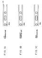
- Figs. 1A to 1C show changes of the record bit relative to a variation of temperature.
- Fig. 1A shows a record bit 40a in low temperature recording
- Fig. 1B shows a record bit 40b in ordinary temperature recording
- Fig. 1C shows a record bit 40c in high temperature recording. Recording conditions other than the temperature are identical. As seen from Figs. 1A - 1C, the higher the temperature is, the larger is the area of the record bit and the more does the edge position of the record bit change.
- Patent abstracts of Japan vol.8, No. 6(P-247) 12/1/1984 & JP-A-58-169303 disclose a magneto-optic recording method in which information is written on the magneto-optic recording medium using a modulated magnetic field, whilst the recording area is heated by a preheating light beam, to enable the recording area of the medium to heat to a higher temperature if the illuminating laser beam has a low power to increase the speed of recording.
- Patent abstracts of Japan vol.8, No. 257 (P-316) 24/11/1984 & JP-A-59-127242 disclose an optical recording and/or reproducing apparatus in which data is written onto a metal film utilising a preheating light beam which preheats the recording region of the recording medium before writing the information to enable the recording time to be decreased.
- Patent abstracts of Japan, vol.11, No. 45 (P-546) [2492], 10/2/1987 & JP-A-61-214266 disclose a magneto-optic recording and/or reproducing apparatus in which the recording bits are recorded by application of a magnetic field pulse in the presence of an illuminating laser beam for raising the temperature of the film.
- the temperature of the recording medium is controlled by a laser drive section which also controls the intensity of laser light in response to the information signal.
- a first aspect of the present invention provides an optical information recording apparatus as set out in claim 1.
- a second aspect of the present invention provides an optical information reproducing apparatus as set out in claim 3.
- a third aspect of the present invention provides a method of recording information as set out in claim 7.
- a fourth aspect of the present invention provides a method of reproducing information as set out in claim 8.
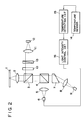
- FIG. 2 shows a configuration of an optical head optical system in the optical information recording and/or reproducing apparatus of the present invention.
- numeral 1 denotes an optical disk which is an optical information recording medium
- numeral 2 denotes an objective lens for condensing a light beam of a light source.
- the light source includes a semiconductor laser 6 for irradiating a preheating light beam and a semiconductor laser 9 for irradiating a recording light beam.
- the light beam of the preheating semiconductor laser 6 is collimated by a collimator lens 5, reflected by a beam splitter 4, passes through a beam splitter 3 and is directed to the objective lens 2.
- the incident light beam is condensed by the objective lens 2 and irradiated onto a recording layer of the optical disk 1 as a light spot 22 as shown in Fig. 3.
- the light beam of the recording semiconductor laser 9 which has a different wavelength from that of the preheating semiconductor laser 6 is collimated by a collimator lens 8 and converted to a circular beam by a beam shaping prism 7.
- the converted light beam passes through the beam splitters 4 and 3 and is directed to the objective lens 2.
- the incident light beam is condensed by the objective lens 2 and irradiated onto the recording layer of the optical disk 1 as a light spot 23 as shown in Fig. 3.
- the recording light spot 23 is irradiated such that it is located on an information track between tracking tracks 21.
- the preheating light spot 22 is sufficiently larger in size than the light spot 23 so that it irradiates the light spot 23 and its peripheral region.
- a light intensity of the recording light beam is modulated by a modulator (not shown) in accordance with a record signal.
- the recording layer is preheated by the preheating light beam to a temperature which does not cause the recording of information, and the intensity-modulated recording light beam is irradiated thereon to record the information.
- the light intensity of the recording semiconductor laser 9 is lowered to a reproducing power, and the reproducing light beam is irradiated to the optical disk 1 like the recording mode.
- the irradiated light beam is reflected by the optical disk 1, passes through the objective lens 2 and is directed to the beam splitter 3.
- the beam splitter 3 reflects the incident light beam to the reproducing light beam detection optical system.
- the detection optical system only the light beam of the semiconductor laser 9 is transmitted through a wavelength filter 10 and the light beam of the semiconductor laser 6 is blocked.
- the reproducing light beam transmitted through the wavelength filter 10 passes through an analyzer 13 and a focusing lens 11 and is detected by a photo-detector 12.
- the analyzer 13 is arranged because a polarized light is utilized when the optical disk 1 is a magneto-optical recording medium.
- a temperature sensor 14 shown in Fig. 2 senses an internal or external temperature of the apparatus, that is, an environmental temperature.
- a temperature detector 15 supplies a control signal which varies with the sensed output of the temperature sensor 14, to a light intensity control circuit 16, which controls the light intensity of the preheating semiconductor laser 6 in accordance with the control signal. It controls such that when the environmental temperature sensed by the temperature sensor 14 rises, the light intensity is lowered, and when the environmental temperature drops, the light intensity is increased. In this manner, the temperature of the recording layer in the irradiation area of the preheating light spot 22 is maintained constant without regard to the environmental temperature.
- Fig. 4 shows a relation between the light intensity of the light beam and the temperature of the recording layer of the optical disk.
- T B denotes a steady temperature by the preheating light beam and T o denotes the environmental temperature.
- T o denotes the environmental temperature.
- the steady temperature T B is set to a temperature which does not cause the recording of of the information.
- Tw denotes the recording temperature and Tr denotes the reproducing temperature.
- the light intensity of the recording semiconductor laser 9 is modulated within the temperature range.
- the recording spot irradiation area on the optical disk 1 can be maintained at the predetermined reproducing temperature Tr or recording temperature T w . Accordingly, the recording condition of the information is kept constant irrespective of the temperature. Thus, the problem of variation of the edge position of the record bit which was encountered in the prior art apparatus is solved and the information can be exactly recorded.
- Fig. 5 shows a relation between a coercive force of the magneto-optical recording medium and a temperature.
- a coercive force Hc at a room temperature gradually decreases as the temperature rises and reaches zero at Curie point Tc.
- a material having such a characteristic is an amorphous film of TbFeCo. It is also known that a Kerr effect decreases as the temperature rises, as the coercive force does. Accordingly, the temperature of the medium may be indirectly detected from an amplitude of a signal reproduced by using the Kerr effect.
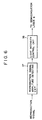
- Fig. 6 shows the embodiment based on the above finding.
- Numeral 17 denotes a reproduced signal amplitude detector for detecting the amplitude of the reproduced signal of the photo-detector 12.
- Numeral 16 denotes a light intensity control circuit which is identical to that shown in Fig. 2 and which controls the light intensity of the preheating semiconductor laser 6 in accordance with the reproduced signal amplitude.
- the medium temperature can be kept constant as it is in the previous embodiment.
- the present invention is not limited to the above embodiments. For example, data recorded under a predetermined temperature environment may be recorded in a monitor area of the medium as a medium temperature reference and the light intensity of the preheating light beam may be corrected prior to the recording.
- the light intensity of the preheating light beam is varied in accordance with the environmental temperature so that the medium temperature can be maintained at the predetermined temperature even if the environmental temperature changes. Accordingly, the information can always be recorded under the constant temperature condition and the change of the size or length of the record bit due to the temperature change is reduced and the information can be exactly recorded. The effect is particularly great in the bit edge recording in which the significance of information is in the edge position of the record bit.
Description
- The present invention relates to an information recording and/or reproducing apparatus for recording information on an optical information recording medium and/or reproducing the information, and more particularly to an optical information recording and/or reproducing apparatus which is suitable for bit edge recording (which is also called pit edge recording).
- As the information is more and more utilized, a large capacity information recording and/or reproducing apparatus is required. An optical information recording and/or reproducing apparatus which optically records and/or reproduces information has been attracting a notice as one which meets the above requirement. An information recording mode in such an optical information recording and/or reproducing apparatus includes bit position recording (mark interval recording) in which the significance of the information is in the position of the center of the record bit, and bit edge recording (mark length recording) in which the significance of the information is in the position of the bit edge. The bit position recording has a characteristic of exactly recording the information while the bit edge recording has an advantage that a recording density is 1.5 times as high as that of the bit position recording.
Accordingly, the bit edge recording is advantageous for higher density recording and the study on the bit edge recording has been actively done recently. - However, the prior art bit edge recording has the following problem. In so-called heat mode recording in which a photo-energy is converted to a thermal energy which is used to record the information, edge positions of the beginning and the end of the record bit are determined by a critical temperature at the time of the recording.
Accordingly, the edge position of the record bit is easily affected by a surrounding temperature of the apparatus and an internal temperature. Figs. 1A to 1C show changes of the record bit relative to a variation of temperature. Fig. 1A shows arecord bit 40a in low temperature recording, Fig. 1B shows arecord bit 40b in ordinary temperature recording, and Fig. 1C shows arecord bit 40c in high temperature recording.
Recording conditions other than the temperature are identical. As seen from Figs. 1A - 1C, the higher the temperature is, the larger is the area of the record bit and the more does the edge position of the record bit change. - Patent abstracts of Japan vol.8, No. 6(P-247) 12/1/1984 & JP-A-58-169303 disclose a magneto-optic recording method in which information is written on the magneto-optic recording medium using a modulated magnetic field, whilst the recording area is heated by a preheating light beam, to enable the recording area of the medium to heat to a higher temperature if the illuminating laser beam has a low power to increase the speed of recording.
- Patent abstracts of Japan vol.8, No. 257 (P-316) 24/11/1984 & JP-A-59-127242 disclose an optical recording and/or reproducing apparatus in which data is written onto a metal film utilising a preheating light beam which preheats the recording region of the recording medium before writing the information to enable the recording time to be decreased.
- Patent abstracts of Japan, vol.11, No. 45 (P-546) [2492], 10/2/1987 & JP-A-61-214266 disclose a magneto-optic recording and/or reproducing apparatus in which the recording bits are recorded by application of a magnetic field pulse in the presence of an illuminating laser beam for raising the temperature of the film. The temperature of the recording medium is controlled by a laser drive section which also controls the intensity of laser light in response to the information signal.
- It is an object of the present invention to provide an optical information recording and/or reproducing apparatus which can exactly record information irrespective of the temperature change.
- A first aspect of the present invention provides an optical information recording apparatus as set out in claim 1.
- A second aspect of the present invention provides an optical information reproducing apparatus as set out in claim 3.
- A third aspect of the present invention provides a method of recording information as set out in claim 7.
- A fourth aspect of the present invention provides a method of reproducing information as set out in
claim 8. -
- Figs. 1A to 1C illustrate that size and length of a record bit vary with an environmental temperature,
- Fig. 2 shows a configuration of one embodiment of the optical information recording and/or reproducing apparatus of the present invention,
- Fig. 3 shows a status in which a spot of a preheating light beam and a spot of a recording light beam are irradiated onto a medium surface,
- Fig. 4 shows a relation between a light intensity on the medium surface and a temperature,
- Fig. 5 shows a relation between a temperature of a magneto-optical recording medium and a coercive force, and
- Fig. 6 shows a block diagram of another embodiment.
- An embodiment of the present invention is explained in detail with reference to the drawings. Fig. 2 shows a configuration of an optical head optical system in the optical information recording and/or reproducing apparatus of the present invention.
- In Fig. 2, numeral 1 denotes an optical disk which is an optical information recording medium, and numeral 2 denotes an objective lens for condensing a light beam of a light source. In the present embodiment, the light source includes a
semiconductor laser 6 for irradiating a preheating light beam and a semiconductor laser 9 for irradiating a recording light beam. - The light beam of the preheating
semiconductor laser 6 is collimated by acollimator lens 5, reflected by abeam splitter 4, passes through a beam splitter 3 and is directed to the objective lens 2. The incident light beam is condensed by the objective lens 2 and irradiated onto a recording layer of the optical disk 1 as alight spot 22 as shown in Fig. 3. - On the other hand, the light beam of the recording semiconductor laser 9 which has a different wavelength from that of the preheating
semiconductor laser 6 is collimated by acollimator lens 8 and converted to a circular beam by a beam shaping prism 7. The converted light beam passes through thebeam splitters 4 and 3 and is directed to the objective lens 2. The incident light beam is condensed by the objective lens 2 and irradiated onto the recording layer of the optical disk 1 as alight spot 23 as shown in Fig. 3. In this case, therecording light spot 23 is irradiated such that it is located on an information track betweentracking tracks 21. The preheatinglight spot 22 is sufficiently larger in size than thelight spot 23 so that it irradiates thelight spot 23 and its peripheral region. A light intensity of the recording light beam is modulated by a modulator (not shown) in accordance with a record signal. The recording layer is preheated by the preheating light beam to a temperature which does not cause the recording of information, and the intensity-modulated recording light beam is irradiated thereon to record the information. - When the recorded information is to be reproduced, the light intensity of the recording semiconductor laser 9 is lowered to a reproducing power, and the reproducing light beam is irradiated to the optical disk 1 like the recording mode. The irradiated light beam is reflected by the optical disk 1, passes through the objective lens 2 and is directed to the beam splitter 3. The beam splitter 3 reflects the incident light beam to the reproducing light beam detection optical system. In the detection optical system, only the light beam of the semiconductor laser 9 is transmitted through a
wavelength filter 10 and the light beam of thesemiconductor laser 6 is blocked. The reproducing light beam transmitted through thewavelength filter 10 passes through ananalyzer 13 and a focusinglens 11 and is detected by a photo-detector 12. Theanalyzer 13 is arranged because a polarized light is utilized when the optical disk 1 is a magneto-optical recording medium. - A
temperature sensor 14 shown in Fig. 2 senses an internal or external temperature of the apparatus, that is, an environmental temperature. Atemperature detector 15 supplies a control signal which varies with the sensed output of thetemperature sensor 14, to a lightintensity control circuit 16, which controls the light intensity of the preheatingsemiconductor laser 6 in accordance with the control signal. It controls such that when the environmental temperature sensed by thetemperature sensor 14 rises, the light intensity is lowered, and when the environmental temperature drops, the light intensity is increased. In this manner, the temperature of the recording layer in the irradiation area of the preheatinglight spot 22 is maintained constant without regard to the environmental temperature. - Fig. 4 shows a relation between the light intensity of the light beam and the temperature of the recording layer of the optical disk. In Fig. 4, TB denotes a steady temperature by the preheating light beam and To denotes the environmental temperature. As described above, the steady temperature TB is always constant irrespective of the environmental temperature To. The steady temperature TB is set to a temperature which does not cause the recording of of the information. Tw denotes the recording temperature and Tr denotes the reproducing temperature. The light intensity of the recording semiconductor laser 9 is modulated within the temperature range.
- In the present embodiment, even if the environmental temperature varies, the recording spot irradiation area on the optical disk 1 can be maintained at the predetermined reproducing temperature Tr or recording temperature Tw.
Accordingly, the recording condition of the information is kept constant irrespective of the temperature. Thus, the problem of variation of the edge position of the record bit which was encountered in the prior art apparatus is solved and the information can be exactly recorded. - An embodiment which uses a magneto-optical recording medium as the optical information recording medium is now explained. Fig. 5 shows a relation between a coercive force of the magneto-optical recording medium and a temperature. A coercive force Hc at a room temperature gradually decreases as the temperature rises and reaches zero at Curie point Tc. A material having such a characteristic is an amorphous film of TbFeCo. It is also known that a Kerr effect decreases as the temperature rises, as the coercive force does. Accordingly, the temperature of the medium may be indirectly detected from an amplitude of a signal reproduced by using the Kerr effect.
- Fig. 6 shows the embodiment based on the above finding.
Numeral 17 denotes a reproduced signal amplitude detector for detecting the amplitude of the reproduced signal of the photo-detector 12.Numeral 16 denotes a light intensity control circuit which is identical to that shown in Fig. 2 and which controls the light intensity of the preheatingsemiconductor laser 6 in accordance with the reproduced signal amplitude. In the present embodiment, the medium temperature can be kept constant as it is in the previous embodiment. The present invention is not limited to the above embodiments. For example, data recorded under a predetermined temperature environment may be recorded in a monitor area of the medium as a medium temperature reference and the light intensity of the preheating light beam may be corrected prior to the recording. - In accordance with the present invention, the light intensity of the preheating light beam is varied in accordance with the environmental temperature so that the medium temperature can be maintained at the predetermined temperature even if the environmental temperature changes. Accordingly, the information can always be recorded under the constant temperature condition and the change of the size or length of the record bit due to the temperature change is reduced and the information can be exactly recorded. The effect is particularly great in the bit edge recording in which the significance of information is in the edge position of the record bit.
Claims (10)
- An optical information recording apparatus comprising:means (6, 2) for irradiating an information track of an optical information recording medium (1) with a preheating light beam; andmeans (9) for irradiating said information track of the optical information recording medium (1) with a recording light beam;the apparatus being characterised by further comprising:detection means (14, 15) for detecting the environmental temperature of the apparatus; andmeans (16) for varying the light intensity of the preheating light beam in accordance with the detection result of said detection means (14,15).
- An optical information recording apparatus according to Claim 1, including means for reproducing information from the recording medium (1).
- An optical information reproducing apparatus comprising:means (6, 2) for irradiating an information track of a magneto-optical information recording medium (1) with a preheating light beam during reproduction;means for irradiating said information track of the magneto-optical information recording medium (1) with a reproducing light beam;the apparatus being characterised by further comprising:detection means (14, 15) for detecting the environmental temperature of the apparatus; andmeans (16) for varying the light intensity of the preheating light beam in accordance with the detection result of said detection means (14,15).
- An apparatus according to claim 1 or claim 2, wherein said optical information recording medium (1) is a magneto-optical recording medium.
- An apparatus according to any one of the preceding claims in which the preheating light beam and the recording light beam are of different wavelengths.
- An apparatus according to any one of the preceding claims when dependent upon claims 2 or claim 3, in which the preheating light beam and the reproducing light beam are of different wavelengths.
- A method of recording information using an optical information recording apparatus, said method comprising the steps of:irradiating an information track of an optical information recording medium (1) with a preheating light beam; andirradiating said information track of the optical information recording medium (1) with a recording light beam;the method being characterised by comprising the further steps of:detecting the environmental temperature of the apparatus; andvarying the light intensity of the preheating light beam in accordance with the detection result.
- A method of reproducing information using an optical information reproducing apparatus, said method comprising the steps of:irradiating an information track of a magneto-optical information recording medium (1) with a preheating light beam; andirradiating said information track of the magneto-optical information recording medium with a reproducing light beam;the method being characterised by comprising the further steps of:detecting the environmental temperature of the apparatus; andvarying the light intensity of the preheating light beam in accordance with the detection result.
- A method according to Claims 7, in which the recording medium (1) is a magneto-optical recording medium.
- A method according to any one of Claims 7 to 9, in which the preheating light beam and recording light beam are of different wavelengths.
Applications Claiming Priority (2)
| Application Number | Priority Date | Filing Date | Title |
|---|---|---|---|
| JP321119/90 | 1990-11-27 | ||
| JP2321119A JP2851014B2 (en) | 1990-11-27 | 1990-11-27 | Information recording device |
Publications (3)
| Publication Number | Publication Date |
|---|---|
| EP0488648A2 EP0488648A2 (en) | 1992-06-03 |
| EP0488648A3 EP0488648A3 (en) | 1992-09-23 |
| EP0488648B1 true EP0488648B1 (en) | 1997-10-29 |
Family
ID=18129033
Family Applications (1)
| Application Number | Title | Priority Date | Filing Date |
|---|---|---|---|
| EP91310879A Expired - Lifetime EP0488648B1 (en) | 1990-11-27 | 1991-11-26 | Optical information recording/reproducing apparatus |
Country Status (4)
| Country | Link |
|---|---|
| US (1) | US5297128A (en) |
| EP (1) | EP0488648B1 (en) |
| JP (1) | JP2851014B2 (en) |
| DE (1) | DE69128067T2 (en) |
Families Citing this family (16)
| Publication number | Priority date | Publication date | Assignee | Title |
|---|---|---|---|---|
| JP3239962B2 (en) * | 1992-09-10 | 2001-12-17 | キヤノン株式会社 | Optical information recording / reproducing device |
| US5610879A (en) * | 1993-03-05 | 1997-03-11 | Matsushita Electric Industrial Co. Ltd. | Optical reproducing device, optical reproducing method using the same, and optical record medium used in the same |
| WO1994022139A1 (en) * | 1993-03-15 | 1994-09-29 | Nikon Corporation | Magnetooptic recording method, magnetooptic recording medium and magentooptic recording apparatus |
| US5461603A (en) * | 1993-04-22 | 1995-10-24 | Sony Corporation | Disc recording/reproducing apparatus having temperature control of the recording/reproducing processes |
| JPH07130080A (en) * | 1993-11-02 | 1995-05-19 | Olympus Optical Co Ltd | Information recorder |
| JP3333613B2 (en) * | 1993-12-07 | 2002-10-15 | 株式会社日立製作所 | Optical information recording medium, optical information recording / reproducing method, and optical information recording / reproducing apparatus |
| US5477520A (en) * | 1994-08-26 | 1995-12-19 | Eastman Kodak Company | System and method for high resolution optical recording using an induced shift in media absorption |
| JPH08147744A (en) * | 1994-11-16 | 1996-06-07 | Canon Inc | Optical recording device |
| US5537383A (en) * | 1995-03-01 | 1996-07-16 | Eastman Kodak Company | Optical data storage system with differential data detection and source noise subtraction for use with magneto-optic, write-once and other optical media |
| JPH097178A (en) * | 1995-06-15 | 1997-01-10 | Nikon Corp | Method and device for reproducing optical disk and optical disk |
| US5742566A (en) * | 1995-11-27 | 1998-04-21 | Sony Corporation | Optical recording methods and apparatus using light modulation technique based on detecting temperature of the medium |
| US6047289A (en) * | 1997-11-07 | 2000-04-04 | Novell, Inc. | Method and apparatus for directed data propagation |
| US6069853A (en) * | 1998-08-21 | 2000-05-30 | Terastor Corporation | Head including a heating element for reducing signal distortion in data storage systems |
| JP3876281B2 (en) * | 2000-08-31 | 2007-01-31 | 独立行政法人産業技術総合研究所 | Information recording method |
| JP2002298360A (en) | 2001-03-30 | 2002-10-11 | Canon Inc | Method and device for recording information in information recording medium |
| JP2007122773A (en) * | 2005-10-25 | 2007-05-17 | Canon Inc | Recording strategy in multi-value recording |
Family Cites Families (7)
| Publication number | Priority date | Publication date | Assignee | Title |
|---|---|---|---|---|
| US3631415A (en) * | 1969-09-12 | 1971-12-28 | Honeywell Inc | Optical mass memory |
| US4530080A (en) * | 1981-04-07 | 1985-07-16 | Tdk Electronics Co., Ltd. | Optical recording/reproducing system |
| JPS58169303A (en) * | 1982-03-30 | 1983-10-05 | Fujitsu Ltd | Photomagnetic recording method |
| JPS59127242A (en) * | 1983-01-06 | 1984-07-23 | Nec Corp | Optical recording and writing device |
| JPS60236137A (en) * | 1984-05-08 | 1985-11-22 | Nippon Kogaku Kk <Nikon> | Simultaneously erasing-recording type photomagnetic recording system and recording device and medium used for this system |
| JPS61214266A (en) * | 1985-03-20 | 1986-09-24 | Hitachi Ltd | Photomagnetic recording and reproducing device |
| JPH0777025B2 (en) * | 1985-10-16 | 1995-08-16 | 株式会社日立製作所 | Optical recording / reproducing device |
-
1990
- 1990-11-27 JP JP2321119A patent/JP2851014B2/en not_active Expired - Fee Related
-
1991
- 1991-11-26 EP EP91310879A patent/EP0488648B1/en not_active Expired - Lifetime
- 1991-11-26 DE DE69128067T patent/DE69128067T2/en not_active Expired - Fee Related
-
1992
- 1992-12-02 US US07/984,740 patent/US5297128A/en not_active Expired - Fee Related
Also Published As
| Publication number | Publication date |
|---|---|
| US5297128A (en) | 1994-03-22 |
| DE69128067D1 (en) | 1997-12-04 |
| JPH04192120A (en) | 1992-07-10 |
| JP2851014B2 (en) | 1999-01-27 |
| EP0488648A2 (en) | 1992-06-03 |
| DE69128067T2 (en) | 1998-03-19 |
| EP0488648A3 (en) | 1992-09-23 |
Similar Documents
| Publication | Publication Date | Title |
|---|---|---|
| EP0559391B1 (en) | Magnetooptical recording/reproducing method and apparatus | |
| EP0488648B1 (en) | Optical information recording/reproducing apparatus | |
| EP0454038B1 (en) | Method of controlling a recording laser beam | |
| EP0653749B1 (en) | Optical information recording/reproducing apparatus and method with function of adjusting reproducing power | |
| US6246641B1 (en) | Magneto-optical recording-reproducing method and apparatus utilizing domain wall displacement | |
| EP0594406B1 (en) | Optical recording method and apparatus | |
| JPH01269261A (en) | Magneto-optical recording and reproducing device | |
| EP0220023B1 (en) | Optical magnetic memory device | |
| US5357493A (en) | Magneto-optic memory device for overwriting information on magneto-optic recording medium by using a pair of light spots without using an external magnetic field | |
| US5966347A (en) | Apparatus and method for reproducing data from a magneto-optic recording medium | |
| KR19990060578A (en) | Method and apparatus for recording data on magneto-optical recording media | |
| EP0595626B1 (en) | Recording condition determination method and apparatus upon execution of over-write operation on magnetooptical disk by heat shut off method and pulse train method, and magnetooptical recording method and apparatus | |
| JPS6355737A (en) | Optical information recording and reproducing device | |
| JPH01191330A (en) | Optical information processor | |
| JP3102714B2 (en) | Magneto-optical recording device | |
| JP3249000B2 (en) | Optical information recording / reproducing device | |
| JPH01196733A (en) | Optical information recording and reproducing device | |
| JP2856375B2 (en) | Magneto-optical recording / reproducing device | |
| JPH04325935A (en) | Optical recording and reproducing device | |
| JP3271205B2 (en) | Optical head device | |
| JPH01191329A (en) | Optical information processor | |
| JPH01191328A (en) | Cartridge and optical information processor using cartridge | |
| WO2005024816A1 (en) | Method for thermal treatment judgment on magneto-optical information recording medium and device for thermal treatment judgment | |
| JPH09190669A (en) | Information reproducing device and reproducing method for optical recording medium | |
| JPS59144049A (en) | Optical recording and reproducing system |
Legal Events
| Date | Code | Title | Description |
|---|---|---|---|
| PUAI | Public reference made under article 153(3) epc to a published international application that has entered the european phase |
Free format text: ORIGINAL CODE: 0009012 |
|
| AK | Designated contracting states |
Kind code of ref document: A2 Designated state(s): DE FR GB IT NL |
|
| PUAL | Search report despatched |
Free format text: ORIGINAL CODE: 0009013 |
|
| AK | Designated contracting states |
Kind code of ref document: A3 Designated state(s): DE FR GB IT NL |
|
| 17P | Request for examination filed |
Effective date: 19930208 |
|
| 17Q | First examination report despatched |
Effective date: 19950130 |
|
| GRAG | Despatch of communication of intention to grant |
Free format text: ORIGINAL CODE: EPIDOS AGRA |
|
| GRAH | Despatch of communication of intention to grant a patent |
Free format text: ORIGINAL CODE: EPIDOS IGRA |
|
| GRAH | Despatch of communication of intention to grant a patent |
Free format text: ORIGINAL CODE: EPIDOS IGRA |
|
| GRAA | (expected) grant |
Free format text: ORIGINAL CODE: 0009210 |
|
| AK | Designated contracting states |
Kind code of ref document: B1 Designated state(s): DE FR GB IT NL |
|
| PG25 | Lapsed in a contracting state [announced via postgrant information from national office to epo] |
Ref country code: IT Free format text: LAPSE BECAUSE OF FAILURE TO SUBMIT A TRANSLATION OF THE DESCRIPTION OR TO PAY THE FEE WITHIN THE PRE;WARNING: LAPSES OF ITALIAN PATENTS WITH EFFECTIVE DATE BEFORE 2007 MAY HAVE OCCURRED AT ANY TIME BEFORE 2007. THE CORRECT EFFECTIVE DATE MAY BE DIFFERENT FROM THE ONE RECORDED.SCRIBED TIME-LIMIT Effective date: 19971029 Ref country code: NL Free format text: LAPSE BECAUSE OF FAILURE TO SUBMIT A TRANSLATION OF THE DESCRIPTION OR TO PAY THE FEE WITHIN THE PRESCRIBED TIME-LIMIT Effective date: 19971029 |
|
| ET | Fr: translation filed | ||
| REF | Corresponds to: |
Ref document number: 69128067 Country of ref document: DE Date of ref document: 19971204 |
|
| NLV1 | Nl: lapsed or annulled due to failure to fulfill the requirements of art. 29p and 29m of the patents act | ||
| PLBE | No opposition filed within time limit |
Free format text: ORIGINAL CODE: 0009261 |
|
| STAA | Information on the status of an ep patent application or granted ep patent |
Free format text: STATUS: NO OPPOSITION FILED WITHIN TIME LIMIT |
|
| 26N | No opposition filed | ||
| REG | Reference to a national code |
Ref country code: GB Ref legal event code: IF02 |
|
| PGFP | Annual fee paid to national office [announced via postgrant information from national office to epo] |
Ref country code: GB Payment date: 20031112 Year of fee payment: 13 |
|
| PGFP | Annual fee paid to national office [announced via postgrant information from national office to epo] |
Ref country code: FR Payment date: 20031125 Year of fee payment: 13 |
|
| PGFP | Annual fee paid to national office [announced via postgrant information from national office to epo] |
Ref country code: DE Payment date: 20031126 Year of fee payment: 13 |
|
| PG25 | Lapsed in a contracting state [announced via postgrant information from national office to epo] |
Ref country code: GB Free format text: LAPSE BECAUSE OF NON-PAYMENT OF DUE FEES Effective date: 20041126 |
|
| PG25 | Lapsed in a contracting state [announced via postgrant information from national office to epo] |
Ref country code: DE Free format text: LAPSE BECAUSE OF NON-PAYMENT OF DUE FEES Effective date: 20050601 |
|
| GBPC | Gb: european patent ceased through non-payment of renewal fee |
Effective date: 20041126 |
|
| PG25 | Lapsed in a contracting state [announced via postgrant information from national office to epo] |
Ref country code: FR Free format text: LAPSE BECAUSE OF NON-PAYMENT OF DUE FEES Effective date: 20050729 |
|
| REG | Reference to a national code |
Ref country code: FR Ref legal event code: ST |