EP0488390A1 - Plastic optical fibers - Google Patents
Plastic optical fibers Download PDFInfo
- Publication number
- EP0488390A1 EP0488390A1 EP91120574A EP91120574A EP0488390A1 EP 0488390 A1 EP0488390 A1 EP 0488390A1 EP 91120574 A EP91120574 A EP 91120574A EP 91120574 A EP91120574 A EP 91120574A EP 0488390 A1 EP0488390 A1 EP 0488390A1
- Authority
- EP
- European Patent Office
- Prior art keywords
- optical fiber
- clad
- polymer
- core
- copolymer
- Prior art date
- Legal status (The legal status is an assumption and is not a legal conclusion. Google has not performed a legal analysis and makes no representation as to the accuracy of the status listed.)
- Withdrawn
Links
- 239000013308 plastic optical fiber Substances 0.000 title claims abstract description 30
- 229920001577 copolymer Polymers 0.000 claims abstract description 41
- 239000000178 monomer Substances 0.000 claims abstract description 35
- YSYRISKCBOPJRG-UHFFFAOYSA-N 4,5-difluoro-2,2-bis(trifluoromethyl)-1,3-dioxole Chemical compound FC1=C(F)OC(C(F)(F)F)(C(F)(F)F)O1 YSYRISKCBOPJRG-UHFFFAOYSA-N 0.000 claims abstract description 20
- 230000009477 glass transition Effects 0.000 claims abstract description 18
- 229910052731 fluorine Inorganic materials 0.000 claims abstract description 7
- 229910052739 hydrogen Inorganic materials 0.000 claims abstract description 5
- 229910052801 chlorine Inorganic materials 0.000 claims abstract description 4
- 229910052805 deuterium Inorganic materials 0.000 claims abstract description 4
- 229920001519 homopolymer Polymers 0.000 claims abstract description 4
- 239000013307 optical fiber Substances 0.000 claims description 98
- 229920000642 polymer Polymers 0.000 claims description 84
- 239000011241 protective layer Substances 0.000 claims description 26
- 238000009987 spinning Methods 0.000 claims description 21
- 239000010410 layer Substances 0.000 claims description 18
- 239000000835 fiber Substances 0.000 claims description 13
- 238000005253 cladding Methods 0.000 claims description 11
- 239000000203 mixture Substances 0.000 claims description 11
- 230000005540 biological transmission Effects 0.000 abstract description 32
- 239000000306 component Substances 0.000 abstract description 5
- 125000003709 fluoroalkyl group Chemical group 0.000 abstract description 5
- 239000008358 core component Substances 0.000 abstract description 2
- 239000011162 core material Substances 0.000 description 51
- 238000005452 bending Methods 0.000 description 25
- 238000000034 method Methods 0.000 description 24
- -1 α -fluoro acrylic acid fluoroalkyl ester Chemical class 0.000 description 15
- BFKJFAAPBSQJPD-UHFFFAOYSA-N tetrafluoroethene Chemical group FC(F)=C(F)F BFKJFAAPBSQJPD-UHFFFAOYSA-N 0.000 description 12
- 239000000463 material Substances 0.000 description 11
- 239000004014 plasticizer Substances 0.000 description 10
- 239000000155 melt Substances 0.000 description 8
- 238000000576 coating method Methods 0.000 description 7
- 238000002074 melt spinning Methods 0.000 description 7
- 238000000926 separation method Methods 0.000 description 7
- 229920003229 poly(methyl methacrylate) Polymers 0.000 description 6
- 239000004926 polymethyl methacrylate Substances 0.000 description 6
- BQCIDUSAKPWEOX-UHFFFAOYSA-N 1,1-Difluoroethene Chemical compound FC(F)=C BQCIDUSAKPWEOX-UHFFFAOYSA-N 0.000 description 5
- KYKAJFCTULSVSH-UHFFFAOYSA-N chloro(fluoro)methane Chemical compound F[C]Cl KYKAJFCTULSVSH-UHFFFAOYSA-N 0.000 description 5
- 238000004891 communication Methods 0.000 description 5
- 239000012792 core layer Substances 0.000 description 4
- 229920000058 polyacrylate Polymers 0.000 description 4
- 239000004417 polycarbonate Substances 0.000 description 4
- 239000006188 syrup Substances 0.000 description 4
- 235000020357 syrup Nutrition 0.000 description 4
- XLYOFNOQVPJJNP-UHFFFAOYSA-N water Substances O XLYOFNOQVPJJNP-UHFFFAOYSA-N 0.000 description 4
- 230000009102 absorption Effects 0.000 description 3
- 238000010521 absorption reaction Methods 0.000 description 3
- 230000015572 biosynthetic process Effects 0.000 description 3
- 239000011248 coating agent Substances 0.000 description 3
- 229920002937 d8-PMMA polymer Polymers 0.000 description 3
- 238000000113 differential scanning calorimetry Methods 0.000 description 3
- 229920000515 polycarbonate Polymers 0.000 description 3
- 239000002904 solvent Substances 0.000 description 3
- VXNZUUAINFGPBY-UHFFFAOYSA-N 1-Butene Chemical compound CCC=C VXNZUUAINFGPBY-UHFFFAOYSA-N 0.000 description 2
- UZKWTJUDCOPSNM-UHFFFAOYSA-N 1-ethenoxybutane Chemical compound CCCCOC=C UZKWTJUDCOPSNM-UHFFFAOYSA-N 0.000 description 2
- CSCPPACGZOOCGX-UHFFFAOYSA-N Acetone Chemical compound CC(C)=O CSCPPACGZOOCGX-UHFFFAOYSA-N 0.000 description 2
- YCKRFDGAMUMZLT-UHFFFAOYSA-N Fluorine atom Chemical compound [F] YCKRFDGAMUMZLT-UHFFFAOYSA-N 0.000 description 2
- 101100023124 Schizosaccharomyces pombe (strain 972 / ATCC 24843) mfr2 gene Proteins 0.000 description 2
- PPBRXRYQALVLMV-UHFFFAOYSA-N Styrene Chemical compound C=CC1=CC=CC=C1 PPBRXRYQALVLMV-UHFFFAOYSA-N 0.000 description 2
- 125000000217 alkyl group Chemical group 0.000 description 2
- IISBACLAFKSPIT-UHFFFAOYSA-N bisphenol A Chemical compound C=1C=C(O)C=CC=1C(C)(C)C1=CC=C(O)C=C1 IISBACLAFKSPIT-UHFFFAOYSA-N 0.000 description 2
- 238000006243 chemical reaction Methods 0.000 description 2
- 230000000052 comparative effect Effects 0.000 description 2
- 238000007796 conventional method Methods 0.000 description 2
- 238000001723 curing Methods 0.000 description 2
- 230000006866 deterioration Effects 0.000 description 2
- LSXWFXONGKSEMY-UHFFFAOYSA-N di-tert-butyl peroxide Chemical compound CC(C)(C)OOC(C)(C)C LSXWFXONGKSEMY-UHFFFAOYSA-N 0.000 description 2
- 239000012969 di-tertiary-butyl peroxide Substances 0.000 description 2
- 238000004821 distillation Methods 0.000 description 2
- FJKIXWOMBXYWOQ-UHFFFAOYSA-N ethenoxyethane Chemical compound CCOC=C FJKIXWOMBXYWOQ-UHFFFAOYSA-N 0.000 description 2
- RTZKZFJDLAIYFH-UHFFFAOYSA-N ether Substances CCOCC RTZKZFJDLAIYFH-UHFFFAOYSA-N 0.000 description 2
- 239000011737 fluorine Substances 0.000 description 2
- 239000011521 glass Substances 0.000 description 2
- 238000013007 heat curing Methods 0.000 description 2
- 239000012528 membrane Substances 0.000 description 2
- 150000002734 metacrylic acid derivatives Chemical class 0.000 description 2
- 239000011148 porous material Substances 0.000 description 2
- KTCQQCLZUOZFEI-UHFFFAOYSA-N 1,1,2,2-tetrafluoro-2-[1,1,1,2,3,3-hexafluoro-3-(1,2,2-trifluoroethenoxy)propan-2-yl]oxyethanesulfonyl fluoride Chemical compound FC(F)=C(F)OC(F)(F)C(F)(C(F)(F)F)OC(F)(F)C(F)(F)S(F)(=O)=O KTCQQCLZUOZFEI-UHFFFAOYSA-N 0.000 description 1
- KTZVZZJJVJQZHV-UHFFFAOYSA-N 1-chloro-4-ethenylbenzene Chemical compound ClC1=CC=C(C=C)C=C1 KTZVZZJJVJQZHV-UHFFFAOYSA-N 0.000 description 1
- OVGRCEFMXPHEBL-UHFFFAOYSA-N 1-ethenoxypropane Chemical compound CCCOC=C OVGRCEFMXPHEBL-UHFFFAOYSA-N 0.000 description 1
- QTKPMCIBUROOGY-UHFFFAOYSA-N 2,2,2-trifluoroethyl 2-methylprop-2-enoate Chemical compound CC(=C)C(=O)OCC(F)(F)F QTKPMCIBUROOGY-UHFFFAOYSA-N 0.000 description 1
- HFNSTEOEZJBXIF-UHFFFAOYSA-N 2,2,4,5-tetrafluoro-1,3-dioxole Chemical compound FC1=C(F)OC(F)(F)O1 HFNSTEOEZJBXIF-UHFFFAOYSA-N 0.000 description 1
- 150000003923 2,5-pyrrolediones Chemical class 0.000 description 1
- SMZOUWXMTYCWNB-UHFFFAOYSA-N 2-(2-methoxy-5-methylphenyl)ethanamine Chemical compound COC1=CC=C(C)C=C1CCN SMZOUWXMTYCWNB-UHFFFAOYSA-N 0.000 description 1
- JAHNSTQSQJOJLO-UHFFFAOYSA-N 2-(3-fluorophenyl)-1h-imidazole Chemical compound FC1=CC=CC(C=2NC=CN=2)=C1 JAHNSTQSQJOJLO-UHFFFAOYSA-N 0.000 description 1
- NIXOWILDQLNWCW-UHFFFAOYSA-N 2-Propenoic acid Natural products OC(=O)C=C NIXOWILDQLNWCW-UHFFFAOYSA-N 0.000 description 1
- SZTBMYHIYNGYIA-UHFFFAOYSA-N 2-chloroacrylic acid Chemical class OC(=O)C(Cl)=C SZTBMYHIYNGYIA-UHFFFAOYSA-N 0.000 description 1
- TYCFGHUTYSLISP-UHFFFAOYSA-N 2-fluoroprop-2-enoic acid Chemical class OC(=O)C(F)=C TYCFGHUTYSLISP-UHFFFAOYSA-N 0.000 description 1
- IYMZEPRSPLASMS-UHFFFAOYSA-N 3-phenylpyrrole-2,5-dione Chemical class O=C1NC(=O)C(C=2C=CC=CC=2)=C1 IYMZEPRSPLASMS-UHFFFAOYSA-N 0.000 description 1
- NLHHRLWOUZZQLW-UHFFFAOYSA-N Acrylonitrile Chemical compound C=CC#N NLHHRLWOUZZQLW-UHFFFAOYSA-N 0.000 description 1
- 229920000089 Cyclic olefin copolymer Polymers 0.000 description 1
- 229920000219 Ethylene vinyl alcohol Polymers 0.000 description 1
- CERQOIWHTDAKMF-UHFFFAOYSA-N Methacrylic acid Chemical compound CC(=C)C(O)=O CERQOIWHTDAKMF-UHFFFAOYSA-N 0.000 description 1
- VVQNEPGJFQJSBK-UHFFFAOYSA-N Methyl methacrylate Chemical compound COC(=O)C(C)=C VVQNEPGJFQJSBK-UHFFFAOYSA-N 0.000 description 1
- 229930040373 Paraformaldehyde Natural products 0.000 description 1
- 229920001774 Perfluoroether Polymers 0.000 description 1
- 239000004952 Polyamide Substances 0.000 description 1
- 239000004695 Polyether sulfone Substances 0.000 description 1
- 239000004698 Polyethylene Substances 0.000 description 1
- 239000004721 Polyphenylene oxide Substances 0.000 description 1
- 239000004743 Polypropylene Substances 0.000 description 1
- 229920001328 Polyvinylidene chloride Polymers 0.000 description 1
- XTXRWKRVRITETP-UHFFFAOYSA-N Vinyl acetate Chemical compound CC(=O)OC=C XTXRWKRVRITETP-UHFFFAOYSA-N 0.000 description 1
- 150000001252 acrylic acid derivatives Chemical class 0.000 description 1
- 229920000800 acrylic rubber Polymers 0.000 description 1
- 125000002723 alicyclic group Chemical group 0.000 description 1
- XYLMUPLGERFSHI-UHFFFAOYSA-N alpha-Methylstyrene Chemical compound CC(=C)C1=CC=CC=C1 XYLMUPLGERFSHI-UHFFFAOYSA-N 0.000 description 1
- 229920006125 amorphous polymer Polymers 0.000 description 1
- 238000000149 argon plasma sintering Methods 0.000 description 1
- 125000003118 aryl group Chemical group 0.000 description 1
- 150000001875 compounds Chemical class 0.000 description 1
- GCFAUZGWPDYAJN-UHFFFAOYSA-N cyclohexyl 3-phenylprop-2-enoate Chemical compound C=1C=CC=CC=1C=CC(=O)OC1CCCCC1 GCFAUZGWPDYAJN-UHFFFAOYSA-N 0.000 description 1
- 230000007423 decrease Effects 0.000 description 1
- 125000004431 deuterium atom Chemical group 0.000 description 1
- 229920001971 elastomer Polymers 0.000 description 1
- 239000000806 elastomer Substances 0.000 description 1
- 150000002148 esters Chemical class 0.000 description 1
- 125000004494 ethyl ester group Chemical group 0.000 description 1
- 239000005038 ethylene vinyl acetate Substances 0.000 description 1
- 238000001125 extrusion Methods 0.000 description 1
- 125000000524 functional group Chemical group 0.000 description 1
- HCDGVLDPFQMKDK-UHFFFAOYSA-N hexafluoropropylene Chemical compound FC(F)=C(F)C(F)(F)F HCDGVLDPFQMKDK-UHFFFAOYSA-N 0.000 description 1
- 229920005669 high impact polystyrene Polymers 0.000 description 1
- 239000004797 high-impact polystyrene Substances 0.000 description 1
- 125000004435 hydrogen atom Chemical group [H]* 0.000 description 1
- 229920000554 ionomer Polymers 0.000 description 1
- 230000031700 light absorption Effects 0.000 description 1
- 238000004519 manufacturing process Methods 0.000 description 1
- OVAULROCPRKKJF-UHFFFAOYSA-N methyl 2,2,3,3-tetrafluoro-3-[1,1,1,2,3,3-hexafluoro-3-(1,2,2-trifluoroethenoxy)propan-2-yl]oxypropanoate Chemical compound COC(=O)C(F)(F)C(F)(F)OC(F)(C(F)(F)F)C(F)(F)OC(F)=C(F)F OVAULROCPRKKJF-UHFFFAOYSA-N 0.000 description 1
- 150000004702 methyl esters Chemical group 0.000 description 1
- XJRBAMWJDBPFIM-UHFFFAOYSA-N methyl vinyl ether Chemical compound COC=C XJRBAMWJDBPFIM-UHFFFAOYSA-N 0.000 description 1
- LVHBHZANLOWSRM-UHFFFAOYSA-N methylenebutanedioic acid Natural products OC(=O)CC(=C)C(O)=O LVHBHZANLOWSRM-UHFFFAOYSA-N 0.000 description 1
- 125000004108 n-butyl group Chemical group [H]C([H])([H])C([H])([H])C([H])([H])C([H])([H])* 0.000 description 1
- KZCOBXFFBQJQHH-UHFFFAOYSA-N octane-1-thiol Chemical compound CCCCCCCCS KZCOBXFFBQJQHH-UHFFFAOYSA-N 0.000 description 1
- 230000003287 optical effect Effects 0.000 description 1
- UJMWVICAENGCRF-UHFFFAOYSA-N oxygen difluoride Chemical compound FOF UJMWVICAENGCRF-UHFFFAOYSA-N 0.000 description 1
- 125000005010 perfluoroalkyl group Chemical group 0.000 description 1
- 230000000704 physical effect Effects 0.000 description 1
- 229920003023 plastic Polymers 0.000 description 1
- 239000004033 plastic Substances 0.000 description 1
- 229920001200 poly(ethylene-vinyl acetate) Polymers 0.000 description 1
- 229920005670 poly(ethylene-vinyl chloride) Polymers 0.000 description 1
- 229920002492 poly(sulfone) Polymers 0.000 description 1
- 229920002647 polyamide Polymers 0.000 description 1
- 229920001748 polybutylene Polymers 0.000 description 1
- 229920006393 polyether sulfone Polymers 0.000 description 1
- 229920000573 polyethylene Polymers 0.000 description 1
- 229920000139 polyethylene terephthalate Polymers 0.000 description 1
- 238000006116 polymerization reaction Methods 0.000 description 1
- 239000011116 polymethylpentene Substances 0.000 description 1
- 229920000306 polymethylpentene Polymers 0.000 description 1
- 229920006324 polyoxymethylene Polymers 0.000 description 1
- 229920006380 polyphenylene oxide Polymers 0.000 description 1
- 229920001155 polypropylene Polymers 0.000 description 1
- 229920002635 polyurethane Polymers 0.000 description 1
- 239000004814 polyurethane Substances 0.000 description 1
- 239000005033 polyvinylidene chloride Substances 0.000 description 1
- 230000001681 protective effect Effects 0.000 description 1
- 239000011347 resin Substances 0.000 description 1
- 229920005989 resin Polymers 0.000 description 1
- 125000000999 tert-butyl group Chemical group [H]C([H])([H])C(*)(C([H])([H])[H])C([H])([H])[H] 0.000 description 1
- 229920001169 thermoplastic Polymers 0.000 description 1
- 239000004416 thermosoftening plastic Substances 0.000 description 1
- 150000007934 α,β-unsaturated carboxylic acids Chemical class 0.000 description 1
- 239000004711 α-olefin Substances 0.000 description 1
Images
Classifications
-
- G—PHYSICS
- G02—OPTICS
- G02B—OPTICAL ELEMENTS, SYSTEMS OR APPARATUS
- G02B6/00—Light guides; Structural details of arrangements comprising light guides and other optical elements, e.g. couplings
- G02B6/02—Optical fibres with cladding with or without a coating
- G02B6/02033—Core or cladding made from organic material, e.g. polymeric material
-
- G—PHYSICS
- G02—OPTICS
- G02B—OPTICAL ELEMENTS, SYSTEMS OR APPARATUS
- G02B6/00—Light guides; Structural details of arrangements comprising light guides and other optical elements, e.g. couplings
- G02B6/44—Mechanical structures for providing tensile strength and external protection for fibres, e.g. optical transmission cables
-
- G—PHYSICS
- G02—OPTICS
- G02B—OPTICAL ELEMENTS, SYSTEMS OR APPARATUS
- G02B1/00—Optical elements characterised by the material of which they are made; Optical coatings for optical elements
- G02B1/04—Optical elements characterised by the material of which they are made; Optical coatings for optical elements made of organic materials, e.g. plastics
- G02B1/045—Light guides
- G02B1/046—Light guides characterised by the core material
-
- G—PHYSICS
- G02—OPTICS
- G02B—OPTICAL ELEMENTS, SYSTEMS OR APPARATUS
- G02B1/00—Optical elements characterised by the material of which they are made; Optical coatings for optical elements
- G02B1/04—Optical elements characterised by the material of which they are made; Optical coatings for optical elements made of organic materials, e.g. plastics
- G02B1/045—Light guides
- G02B1/048—Light guides characterised by the cladding material
Definitions
- the present invention relates to a plastic optical fiber. More specifically, the present invention relates to a plastic optical fiber which can be used as optical fiber codes and optical fiber cables.
- Inorganic glass optical fibers have been known as optical fibers which are excellent in light transmission properties over a broad range of wavelengths. However, since said glass optical fibers are not good in processability or flexural strength, plastic optical fibers were developed and have been widely used as optical fibers.
- plastic optical fibers are basically comprised of a core polymer comprising a polymer which has excellent light transmission properties and a high refractive index, such as polymethyl methacrylate (hereinafter referred to as PMMA), polycarbonate (hereinafter referred to as PC), and a clad polymer comprising a transparent polymer which has a refractive index lower than that of the core polymer, such as fluorine-containing polymers.
- a core polymer comprising a polymer which has excellent light transmission properties and a high refractive index, such as polymethyl methacrylate (hereinafter referred to as PMMA), polycarbonate (hereinafter referred to as PC), and a clad polymer comprising a transparent polymer which has a refractive index lower than that of the core polymer, such as fluorine-containing polymers.
- PMMA polymethyl methacrylate
- PC polycarbonate
- clad polymer comprising a transparent polymer which has a refractive index lower than that of the
- plastic optical fibers of this type are optical fiber strands, bulk fibers made by covering optical fiber strands with a functional protective layer, optical fiber codes made by covering optical fiber strands with a jacket, bundle fibers made of an assembly of bulk fibers, and optical fiber cables made by applying tension members to the bulk fibers.
- plastic optical fibers have many C-H bonds in the core polymer, and light absorption based on the stretching vibration of the C-H bonds, appears at the regions of the short wavelengths. Five to eight times harmonic absorptions also appear at the near infrared to visible ray region, namely, at a wavelength of not less than 400 nm. These serious light transmission losses in these regions have to be eliminated to use these conventional plastic optical fibers for light transmission.
- the transmission loss of an optical fiber having a core of PMMA is about 100 dB/Km at a wavelength of 650 nm, and about 400 dB/Km at a wavelength of 780 nm.
- a core polymer comprising d8-PMMA, of which all the H atoms in PMMA are replaced by deuterium atoms, was proposed.
- This optical fiber containing d8-PMMA as a core polymer has a transmission loss of 50 dB/km at a wavelength of 780 nm.
- Deutrated PMMA however, has high water absorbing properties, and the d8-PMMA core polymer absorbs water, and the transmission loss will increase with the lapse of time.
- An optical fiber showing such an increase in transmission loss cannot be used as an optical fiber, as an optical fiber is expected to have a high reliability over a long period.
- LEDs light-emitting diodes
- LAN systems Local-Area Network Systems
- plastic optical fibers that can transmit rays in the near infrared region have been developed.
- an optical fiber comprising a core polymer of a polymer of ⁇ -fluoro acrylic acid fluoroalkyl ester, and a clad copolymer of vinylidene fluoride and tetrafluoroethylene was disclosed in EP 340557 A2 and EP 340555 A2.
- This optical fiber can transmit rays having a wavelength in the near infrared region, but its performance as an optical fiber is not satisfactory, since the difference in the refractive index between the core polymer and the clad polymer is not large enough to make an optical fiber having a large numerical aperture, and thus this optical fiber is not satisfactory as an optical fiber for transmitting data in a great amount. Further, because of its small numerical aperture, it is difficult for this optical fiber to inhibit the leakage of rays from its side surface when it is bent, and thus it is not satisfactory as an optical fiber for data communication.
- the vinylidene fluoride-tetrafluoroethylene copolymer is not a perfectly amorphous polymer, and by this reason, has light-absorbing properties or light-scattering properties. Thus, an optical fiber containing this clad copolymer is not satisfactory in light transmission properties.
- This clad material is proposed to be used in combination with a core material composed of an ⁇ , ⁇ - unsaturated carboxylic acid ester represented by the following general formula (I) as the main component: (wherein X is CH3, H, D, F, Cl, or CF3; y is H or D; and Rf is a fluoroalkyl group having a linear or branched chain).
- a core material composed of an ⁇ , ⁇ - unsaturated carboxylic acid ester represented by the following general formula (I) as the main component: (wherein X is CH3, H, D, F, Cl, or CF3; y is H or D; and Rf is a fluoroalkyl group having a linear or branched chain).
- this core material is glassy and hard, and it is unsatisfactory in its strength for use as an optical fiber.
- this core material As an optical fiber, it is necessary to stretch it to enhance its strength.
- between the glass transition temperature of a clad material made of the copolymer of perfluoro[2,2-dimethyl-1,3-dioxole] (Tg2 (°C )) and at least one other ethylenically unsaturated monomer results in that of this core material (Tg1(°C )) becomes too large, the stretching temperature of the optical fiber becomes too high for a clad material to be stretched, and the properties of this optical fiber being damaged.
- a clad copolymer comprising perfluoro[2,2-dimethyl-1,3-dioxole] as the main monomer does not adhere well to a core material. This is a characteristic feature of a fluorine plastic. If an optical fiber having a core-clad two-layer structure containing this polymer as the core material is bent, the clad layer often separates from the core layer, and the plastic optical fiber decreases in flexibility. Such flexibility is a significant advantage of a plastic optical fiber.
- the core component is composed of a homopolymer or copolymer of a monomer selected from one or more monomers represented by the general formula (I), or a copolymer of the at least one monomer represented by the general formula (I) and other copolymerizable comonomers and which has a glass transition temperature Tg1(°C ); and wherein the clad component is composed of a copolymer of perfluoro[2,2-dimethyl-1,3-dioxole] and one other ethylenically unsaturated monomer and which has a glass transition temperature Tg2(°C ); and which satisfies the relationship of
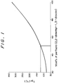
- Fig. 1 is a drawing showing the relationship between the mole% ratio in a clad polymer of a copolymer of perfluoro[2,2-dimethyl-1,3-dioxole] and tetrafluoroethylene and its glass transition temperature Tg2(°C ).
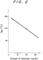
- Fig. 2 is a drawing showing Tg2(°C ) of a copolymer of 60 mole% of perfluoro[2,2-dimethyl-1,3-dioxole] and 40 mole% of tetrafluoroethylene when various amounts of a plasticizer (DEMNUM) are added.
- DEMNUM plasticizer
- the core polymer used in the present invention is a homopolymer or copolymer of a monomer selected from one or more monomers represented by the general formula (I), or a copolymer of the at least one monomer represented by the general formula (I) and other copolymerizable comonomers. (wherein X, Y, and Rf represent the same as mentioned above).
- Examples of the monomer represented by the formula (I) include fluoroalkyl acrylates, ⁇ - fluoroacrylates, ⁇ -chloroacrylates, or methacrylates containing a fluoroalkyl group or a perfluoroalkyl group as Rf.
- Rf group examples include a linear fluoroalkyl group represented by -(CH2)m(CF2)nZ (wherein m is an integer of 0 to 2; n is an integer of 1 to 12; Z is H or F), or -CH2C(CF3)2A (wherein A represents H,D, F, an aliphatic alkyl or alicyclic alkyl group, or an aromatic alkyl group), or -C(CF3)2A (wherein A represents the same as mentioned above).
- the core polymer used in the present invention comprises a polymer constituted from a monomer represented by the formula (I) as the main monomer, and it is preferably constituted from a monomer represented by formula (I) in at least 30 mole%, more preferably in at least 75 mole%. If the content of this monomer is less than 30 mole%, the amount of the C-H bonds in the core polymer becomes high, and the water absorption becomes high. Thus, a plastic optical fiber excellent in light transmission cannot be obtained.
- Examples of the other monomers copolymerizable with the monomer represented by the formula (I) include methacrylates, or acrylates whose ester is methyl ester, ethyl ester, n-butyl ester, t-butyl ester, cyclohexyl ester, phenyl ester, or isobornyl ester, maleimides, phenylmaleimides, acrylic acid, methacrylic acid, itaconic acid, styrene, ⁇ -methylstyrene, p-chlorostyrene, acrylonitrile, and vinyl acetate.
- the refractive index n1 of the core polymer used in the present invention has a relatively low value, and is in the range of 1.33 to 1.46.
- the refractive index n2 of the clad polymer used in the optical fiber of the present invention shall be in the range of from 1.29 to 1.35, and the difference (n1-n2) shall be not less than 0.01, and preferably not less than 0.03.
- the preferable clad copolymer to be used in the present invention is a copolymer of perfluoro[2,2-dimethyl-1,3-dioxole] and at least one other copolymerizable ethylenically unsaturated monomer.
- the perfluoro[2,2-dimethyl-1,3-dioxole] can be prepared by, for example, the method disclosed in USP No. 3,865,845, and its copolymer with the unsaturated monomer can be prepared by, for example, the method disclosed in USP No. 3,978,030.
- the clad polymer shall be amorphous and highly transparent, and has a refractive index in the range of from 1.29 to 1.35.
- the content of the perfluoro[2,2-dimethyl-1,3-dioxole] unit in the clad polymer is in the range of 20 mole% to 100 mole%, preferably in the range of 25.0 to 99.7 mole%.
- the glass transition temperature of the clad copolymer (Tg2 (°C )) varies, for example, in a manner as shown in Fig. 1, depending on the content of the perfluoro[2,2-dimethyl-1,3-dioxole] unit in the clad copolymer.
- a clad copolymer having a desired glass transition temperature can be obtained by controlling the content of the perfluorodioxole in the clad copolymer to have the absolute difference
- plasticizers are preferably added to the clad copolymer to lower its glass transition temperature.
- the plasticizers is a perfluoroalkyl ether having a Mn of not more than 10,000, and it may be added in an amount of 1 to 50 wt%, preferably 5 to 30 wt%, based on 100 wt% of a perfluoro[2,2-dimethyl-1,3-dioxole] polymer having a Mn of not less than 15,000.
- This specific plasticiser is preferably added to the clad polymer, since it has a small tendency to exude.
- the perfluoroalkyl ether include and commercially available ones are that produced by Daikin Kogyo Co., Ltd. under the trademark "Demnum,” or that produced by DuPont Co., Ltd. under the trademark "Krytox".
- the glass transition temperature of the blend of the perfluoro[2,2-dimethyl-1,3-dioxole] copolymer and the plasticizer varies depending on the content of the plasticiser added, and a blend having a desired glass transition temperature can be obtained by controlling the content of the plasticizer.
- Fig. 2 is a figure showing the relation of the glass transition temperature of a blend of a perfluoro[2,2-dimethyl-1,3-dioxole]/tetrafluoroethylene copolymer (60/40 mole%) and a perfluoroether (plasticiser) to the adding ratio of the plasticizer.
- the core-clad type conjugate spinning method the ram extrusion method, the melt coating method for a clad material, and the solvent coating method using a clad material solution, can all be used.
- the melt coating method for a clad material the melt coating method for a clad material
- the solvent coating method using a clad material solution can all be used.
- dust-free conditions are necessary.
- the core-clad type conjugate melt spinning method is the most preferable one.
- the melt flow rate of the core polymer [MFR1] and that of the clad polymer [MFR2] must satisfy the relationship of (MFR1 ⁇ MFR2). If an optical fiber is spun from a core polymer and a clad polymer that do not satisfy this relationship, a regular core-clad structure cannot be obtained, and the light transmission properties of the thus-produced fiber are not excellent.
- the MFR values of a polymer were measured by a method based on the method A stated in JIS K-7210, formulated in 1976. Namely, 5 g of a polymer is filled in a die having a die length of 8 mm and an inner diameter of 2.0 mm and put a load of 5 kg at 230 °C, and the amount of the polymer extruded from the tip of the die for ten minutes is measured. These values were employed as MFR values.
- the plastic optical fiber thus-obtained is excellent in light transmission properties, and can transmit light in the visible-to-near infrared region, since the content of the C-H bonds is small and the water absorption is small.
- the plastic optical fiber of the present invention enables long distance communication exceeding 1 km, and it can be used as an optical fiber in light communication fields such as for LAN and FA.
- the optical fiber of the present invention can provide an optical fiber having a large numerical aperture, since this optical fiber is comprised of a core polymer having a refractive index (n1) of 1.33 to 1.46, and a clad polymer having a refractive index (n2) of 1.29 to 1.35 and the difference (n1-n2) being not less than 0.01.
- the strength and flexibility of the plastic optical fiber are satisfactory, but they can be further improved by stretching the optical fiber made by the conjugate spinning method from 1.2 to 10 times to length, preferably from 1.5 to 5 times, without damaging the light transmission properties.
- the stretching temperature shall be 5 to 50°C higher, preferably 10 to 30°C higher, than the glass transition temperature of the core polymer.
- the plastic optical fiber of the present invention preferably has a concentric three-layer structure wherein a protective layer is further provided on the clad layer, since the protective layer ensures the adherence of the clad layer to the core fiber and thereby further increases the flexibility of the optical fiber.
- a polymer for the protective layer preferably has a breaking extension of not less than 10%.
- the polymers for the protective layer include an ABS (elongation at rupture 40%), a SBR (100%), an ethylene-vinyl alcohol copolymer (200%), an ethylene-vinyl chloride copolymer (170%), an ethylene-vinyl acetate copolymer (800%), an ionomer (370%), a polymethylpentene (10%), a polyethylene (600%), a polypropylene (60%), an ethylene- ⁇ -olefin copolymer (500%), a polycarbonate (100%), a polyamide (100%), a polyoxymethylene (60%), a polyethylene terephtalate (350%), a polybutylene terephtalate (350%), a polyurethane (500%), a high-impact polystyrene (60%), a polyvinylidene chloride (150%), a polyacrylate (50%), a polyethersulfone (60%), a polyphenylene oxide (6
- the thickness of the protective layer is preferably within the range of 1 to 100 ⁇ m. If the thickness is less than 1 ⁇ m, the flexibility of the optical fiber is not sufficient, and the clad layer often separates from the core layer when the optical fiber is bent. If the thickness exceeds 100 ⁇ m, the amount of light that can enter an optical fiber will be limited, since the surface area of the core fiber becomes small in relation to the total surface area of the optical fiber.
- the difference between the refractive index n2 of the clad polymer and the n3 of the protective layer should preferably be not less than 0.05.
- various methods can be used such as 1) the method of forming the concentric core layer-clad layer-the protective layer-structure by the concentric three-layer conjugate melt spinning method; 2) the solvent coating method or light-curing or heat-curing method of the protective layer after the formation of the concentric core-clad structure by the two-layer conjugate melt spinning method; 3) successive applications of the clad layer and protective layer by solvent coating or the coating of a light-curing or heat-curing resin after the formation of the core fiber by melt spinning; and 4) the melt coating method of the protective layer after the formation of the concentric core-clad structure by the conjugate melt spinning method.
- the first method is most preferable in view of its productivity, the uniformity in the fluctuation of the diameter of the optical fiber made, and that in the fluctuation of light transmission loss.
- the plastic optical fiber thus made should preferably be stretched from 1.2 to 10 times, preferably from 1.5 to 5 times its original length, to improve its flex resistance.
- the thus-stretched optical fiber is very good in handling, since no separation of the core layer and clad layer, nor breaking or damaging of the core layer, are observed even after repeated flexing because of the existence of the protective layer.
- All monomers to be used were purified by a conventional method, and they were used immediately after distillation.
- a monomer mixture was obtained by adding 18 ppm of di-tertiarybutyl peroxide and 0.3 wt% of n-octylmercaptane to ⁇ -fluoro 1,1,1,3,3,3-hexafluoroisopropyl acrylate. This mixture was filtrated with a tetrafluoroethylene membrane filter of 0.02 ⁇ m pore size, and then polymerized for 3 hours at 150 °C under a pressure of N2, and a syrup having a polymerization conversion ratio of 54 % was obtained.
- This syrup was continuously fed into a vented extruder to get a polymer containing a residual monomer of not more than 0.5 %.
- This polymer was fed into the core polymer feeding portion in a spinning machine maintained at 180°C.
- the core polymer had a Tg of 103 °C measured by differential scanning calorimetry (DSC) and a refractive index of 1.356.
- a clad copolymer of 50 mole% of perfluoro[2,2-dimethyl-1,3-dioxole] and 50 mole% of tetrafluoroethylene (Tg: 120°C , refractive index: 1.308) was melted with a melt extruder, and was fed into the clad material feeding portion in the spinning machine.
- the fed core and clad polymers were spun through a conjugate spinning nozzle to give an optical fiber having a core-clad structure and an outer diameter of 1.41 mm ⁇ .
- the thus-prepared optical fiber was stretched to twice its length at 135°C , and an optical fiber having an outer diameter of 1 mm ⁇ was obtained.
- the light transmission loss of the optical fiber was very small (87 dB/km at a wavelength of 650 nm; 112 dB/km at a wavelength of 770 nm; 223 dB/km at a wavelength of 950nm).
- the repeating bending test was conducted for this optical fiber in accordance with JIS C 6821-1989 (weight 500 g).
- the optical fiber was subjected to a repeating bending test having a bending cycle (90 in both the right and left directions with respect to the vertical direction) with a curvature having a bending radius R of 10mm.
- the optical fiber was not broken until 12,000 bending cycles.
- An optical fiber having an outer diameter of 1 mm ⁇ was obtained by the same method as that used in Example 1, except that the core forming polymer used was a PMMA.
- the light transmission losses were 129 dB/km at 650 nm, 543 dB/km at 770 pm, and 2,900 dB/km at 950 nm.
- An optical fiber was used that had an outer diameter of 1 mm ⁇ .
- the same polymer as used in Example 1 was used, and the conjugate melt spinning method was used.
- the same repeated flex test used in Example 1 was conducted on this optical fiber, without it being stretched.
- the transmission losses were 93 dB/km at a wavelength of 650 nm, 122 dB/km at 770 nm, and 217 dB/km at 950 nm.
- the optical fiber was broken after 1,000 bending cycles.
- Optical fibers were obtained by using the same core polymers and clad polymers as in Table 1, and by using the same method as in Example 1. The light transmission losses measured and the results of the repeating bending tests are shown in Table 1.
- An optical fiber having an outer diameter of 1.41mm ⁇ was obtained by the conjugate spinning method by using the same core material as used in Example 1 and the clad-forming polymer composition (refractive index 1.307; Tg 100 °C ) comprising 80 wt% of a copolymer of perfluoro[2,2-dimethyl-1,3-dioxole]/tetrafluoroethylene (60/40 mole%) having a Tg of 145°C and 20 wt% of (Mn 8,000; plasticizer Demnum S-200).
- the optical fiber was stretched to twice its original length at 135°C .
- the transmission loss was 85 dB/km at 650 nm.
- the repeated flex test was conducted by using the same method as that used in Example 1, and the optical fiber was not broken until 11,000 bending cycles.
- a clad copolymer having a Tg of 120 °C of 50 mole% of perfluoro[2,2-dimethyl-1,3-dioxole] and 50 mole% of tetrafluoroethylene was melted with a melt extruder, and was fed into the clad material feeding portion in the spinning machine.
- the fed core and clad polymers were spun through a conjugate spinning nozzle to give an optical fiber having a core-clad structure and an outer diameter of 1.41 mm ⁇ .
- This optical fiber was stretched to twice its original length, and an optical fiber having an outer diameter of 1.00 mm ⁇ was obtained.
- the light transmission losses of the thus-produced optical fiber were 95 dB/km at a wavelength of 650 pm, 378 dB/km at a wavelength of 770 pm, and 820 dB/km at a wavelength of 950 pm,
- the same bending test as that used in Example 1 was conducted, and this optical fiber was not broken until 8,000 bending cycles.
- a core-forming polymer having a Tg of 96°C measured by DSC and a refractive index of 1.424 was obtained by the same method as that used in Example 7.
- a clad-forming copolymer of 50 mole% of perfluoro[2,2-dimethyl-1,3-dioxole] and 50 mole% of tetrafluoroethylene was melted with a melt extruder, and was fed into the clad material feeding portion in the spinning machine.
- the clad-forming polymer obtained had a glass transition temperature of 120°C and a refractive index of 1.308.
- a copolymer of 80 mole% of vinylidene fluoride and 20 mole% of tetrafluoroethylene was melted with a melt extruder, and was fed into the protective-layer feeding portion in the spinning machine.
- the polymer obtained had a refractive index of 1.403.
- the three polymers thus fed into the spinning machine were spun through a three-layer conjugate spinning nozzle to give an optical fiber having a core-clad-protective layer structure and an outer diameter of 1.41 mm ⁇ .
- the optical fiber was stretched to twice its length at 135°C , and a stretched optical fiber having an outer diameter of 1 mm ⁇ , a core diameter of 980 ⁇ m, a clad thickness of 5 ⁇ m, and a protective layer thickness of 5 ⁇ m, was obtained.
- the transmission loss of the stretched optical fiber was very small (96 dB/km at 650 nm; 417 dB/km at 770 nm; 1014 dB/km at 950 nm).
- the stretched optical fiber was subjected to a bending having the same bending cycle as that used in Example 1 with a curvature having a bending radius R of 5mm. The optical fiber was not broken until 8,000 bending cycles. No separation of the clad was observed.
- the same core and clad polymers as those used in Example 8 were spun through a concentric two-layer conjugate spinning nozzle to give an optical fiber having a core-clad structure, a core diameter of 990 ⁇ m, and a clad thickness of 5 ⁇ m.
- the transmission loss of the optical fiber thus obtained was very small (101 dB/km at 650 nm; 431 dB/km at 770 nm; 923 dB/km at 950 nm).
- This optical fiber was subjected to the same repeating bending test as that conducted in Example 8. A separation of the cladding was observed around the bending center after 10 bending cycles.
- the same polymers for forming core, clad and protective layers as those used in Example 8 were spun through a three-layer conjugate spinning nozzle to give an optical fiber having an outer diameter of 1 mm ⁇ .
- the transmission losses were 92 dB/km at 650 nm, 420 dB/km at 770 nm, and 942 dB/km at 950 nm.
- This optical fiber was subjected to the same repeating bending test as conducted in Example 8. No separation of the clad was observed, but the optical fiber was broken after 500 bending cycles.
- Example 8 The same core forming polymer and clad forming copolymer as those prepared in Example 8 were fed into the core material feeding portion and the clad material feeding portion in the spinning machine, respectively.
- a bisphenol A type polycarbonate (viscometric average Mw 19,000) was melted with a melt extruder, and then was fed into the protective layer material feeding portion.
- optical fiber having a core-clad-protective layer structure and an outer diameter of 1.41 mm ⁇ .
- This optical fiber was stretched three times its original length at 150 °C , and an optical fiber having a core diameter of 970 ⁇ m, a cladding thickness of 5 ⁇ m, a protective layer thickness of 10 ⁇ m, and an outer diameter of 1 mm ⁇ .
- the transmission loss of this optical fiber was very small (81 dB/km at 650 nm; 98 dB/km at 770 nm: 201 dB/km at 950 nm).
- This optical fiber was subjected to the same repeating bending test. No deterioration of the surface, such as separation of the cladding from the core was observed. The same bending test as that used in Example 8 was conducted, and the optical fiber was not broken until 9,000 bending cycles.
- the core, cladding, and protective layer forming polymers listed in Table 2 were used, and optical fibers having a core diameter of 960 ⁇ m, a cladding thickness of 10 ⁇ m, a protective layer thickness of 10 ⁇ m, and an outer diameter of 1,000 ⁇ m, were obtained by employing the same method as that of Example 8.
- the light transmission loss and flexibility measured were also shown in Table 2.
- the transmission loss at 650 nm was 76 dB/km.
- the same repeating bending test (R: 5mm) was conducted, and no deterioration of the surface, such as the separation of the cladding was observed.
- the optical fiber was not broken until 11,000 bending cycles, and exhibited good mechanical properties.
- Example 14 The same core-forming polymer and clad-forming polymer used in Example 14 were spun through a concentric core-clad two-layer conjugate spinning nozzle to give an optical fiber having a core diameter of 980 ⁇ m, a cladding thickness of 10 ⁇ m, and an outer diameter of 1,000 ⁇ m.
- the transmission loss of this optical fiber was low (65 dB/km at 650 nm).
- the same bending test as used in Example 8 was conducted, and a separation of the cladding was observed around the bending center after 20 bending cycles.
- the core forming polymer and clad forming polymer listed in Table 2 were spun through a concentric conjugate melt spinning nozzle, and the fiber thus spun was stretched to twice its original length at 135 °C to give an optical fiber having an outer diameter of 990 ⁇ m.
- This optical fiber was coated with vinylidene fluoride (acetone solution 20 wt%) by using a coating die, and then the fiber was dried.
- the thus-prepared fiber had an outer diameter of 1 mm ⁇ .
- the physical properties of this optical fiber are shown in Table 2.
Abstract
A novel all-plastic optical fiber comprising core and clad components which is tough, flexible, and which has a low transmission loss, wherein the core component is composed of a homopolymer or copolymer of a monomer selected from one or more monomers represented by the general formula (I), or a copolymer of the at least one monomer represented by the general formula (I) and other copolymerizable comonomers and which has a glass transition temperature Tg₁°C ; and wherein the clad component is composed of a copolymer of perfluoro[2,2-dimethyl-1,3-dioxole] and one other ethylenically unsaturated monomer, and which has a glass transition temperature Tg₂°C ; and which meets the relationship wherein that the absolute difference of |Tg₁ -Tg₂| is not greater than 30°C .

(wherein X is CH₃, H, D, F, Cℓ, or CF₃; Y is H or D; and Rf is a fluoroalkyl group having a linear or branched chain).
(wherein X is CH₃, H, D, F, Cℓ, or CF₃; Y is H or D; and Rf is a fluoroalkyl group having a linear or branched chain).
Description
- The present invention relates to a plastic optical fiber. More specifically, the present invention relates to a plastic optical fiber which can be used as optical fiber codes and optical fiber cables.
- Inorganic glass optical fibers have been known as optical fibers which are excellent in light transmission properties over a broad range of wavelengths. However, since said glass optical fibers are not good in processability or flexural strength, plastic optical fibers were developed and have been widely used as optical fibers.
- These plastic optical fibers are basically comprised of a core polymer comprising a polymer which has excellent light transmission properties and a high refractive index, such as polymethyl methacrylate (hereinafter referred to as PMMA), polycarbonate (hereinafter referred to as PC), and a clad polymer comprising a transparent polymer which has a refractive index lower than that of the core polymer, such as fluorine-containing polymers.
- Known examples of the plastic optical fibers of this type are optical fiber strands, bulk fibers made by covering optical fiber strands with a functional protective layer, optical fiber codes made by covering optical fiber strands with a jacket, bundle fibers made of an assembly of bulk fibers, and optical fiber cables made by applying tension members to the bulk fibers.
- These plastic optical fibers, however, have many C-H bonds in the core polymer, and light absorption based on the stretching vibration of the C-H bonds, appears at the regions of the short wavelengths. Five to eight times harmonic absorptions also appear at the near infrared to visible ray region, namely, at a wavelength of not less than 400 nm. These serious light transmission losses in these regions have to be eliminated to use these conventional plastic optical fibers for light transmission. For example, the transmission loss of an optical fiber having a core of PMMA is about 100 dB/Km at a wavelength of 650 nm, and about 400 dB/Km at a wavelength of 780 nm. To avoid the transmission losses based on the C-H bonds in the core polymer, a core polymer comprising d₈-PMMA, of which all the H atoms in PMMA are replaced by deuterium atoms, was proposed. This optical fiber containing d₈-PMMA as a core polymer has a transmission loss of 50 dB/km at a wavelength of 780 nm. Deutrated PMMA, however, has high water absorbing properties, and the d₈-PMMA core polymer absorbs water, and the transmission loss will increase with the lapse of time. An optical fiber showing such an increase in transmission loss cannot be used as an optical fiber, as an optical fiber is expected to have a high reliability over a long period.
- At present light-emitting diodes (LEDs) that can emit rays in the near infrared region, and which have high power, and which can be used for high-speed data transmission, have been produced in large quantities at a low cost. Since conventional plastic optical fibers, however, cannot use these LEDs as a light source for optical communications, light transmission beyond a wave guide length longer than 100 m cannot be accomplished with one optical fiber. Thus, LAN systems (Local-Area Network Systems) using plastic optical fibers have not been so widespread.
- Recently, plastic optical fibers that can transmit rays in the near infrared region have been developed. For example, an optical fiber comprising a core polymer of a polymer of α -fluoro acrylic acid fluoroalkyl ester, and a clad copolymer of vinylidene fluoride and tetrafluoroethylene was disclosed in EP 340557 A2 and EP 340555 A2. This optical fiber can transmit rays having a wavelength in the near infrared region, but its performance as an optical fiber is not satisfactory, since the difference in the refractive index between the core polymer and the clad polymer is not large enough to make an optical fiber having a large numerical aperture, and thus this optical fiber is not satisfactory as an optical fiber for transmitting data in a great amount. Further, because of its small numerical aperture, it is difficult for this optical fiber to inhibit the leakage of rays from its side surface when it is bent, and thus it is not satisfactory as an optical fiber for data communication.
- Furthermore, the vinylidene fluoride-tetrafluoroethylene copolymer is not a perfectly amorphous polymer, and by this reason, has light-absorbing properties or light-scattering properties. Thus, an optical fiber containing this clad copolymer is not satisfactory in light transmission properties.
- As a transparent clad material having a low refractive index, a copolymer of perfluoro[2,2-dimethyl-1,3-dioxole) and at least one other ethylenically unsaturated monomer has been reported.
- This clad material is proposed to be used in combination with a core material composed of an α , β - unsaturated carboxylic acid ester represented by the following general formula (I) as the main component:

(wherein X is CH₃, H, D, F, Cℓ, or CF₃; y is H or D; and Rf is a fluoroalkyl group having a linear or branched chain). - However, this core material is glassy and hard, and it is unsatisfactory in its strength for use as an optical fiber.
- To use this core material as an optical fiber, it is necessary to stretch it to enhance its strength. However, the absolute difference |Tg₁-Tg₂| between the glass transition temperature of a clad material made of the copolymer of perfluoro[2,2-dimethyl-1,3-dioxole] (Tg₂ (°C )) and at least one other ethylenically unsaturated monomer results in that of this core material (Tg₁(°C )) becomes too large, the stretching temperature of the optical fiber becomes too high for a clad material to be stretched, and the properties of this optical fiber being damaged.
- In addition to this problem, a clad copolymer comprising perfluoro[2,2-dimethyl-1,3-dioxole] as the main monomer does not adhere well to a core material. This is a characteristic feature of a fluorine plastic. If an optical fiber having a core-clad two-layer structure containing this polymer as the core material is bent, the clad layer often separates from the core layer, and the plastic optical fiber decreases in flexibility. Such flexibility is a significant advantage of a plastic optical fiber.
- It is a general object of the present invention to provide an all-plastic optical fiber which is excellent in light transmission properties and which is suitable as an optical fiber for long distance light communication.
- More specifically, in accordance with the present invention, there is provided a novel all-plastic optical fiber having core and clad components which avoid all of the above-noted problems, wherein the core component is composed of a homopolymer or copolymer of a monomer selected from one or more monomers represented by the general formula (I), or a copolymer of the at least one monomer represented by the general formula (I) and other copolymerizable comonomers and which has a glass transition temperature Tg₁(°C ); and wherein the clad component is composed of a copolymer of perfluoro[2,2-dimethyl-1,3-dioxole] and one other ethylenically unsaturated monomer and which has a glass transition temperature Tg₂(°C ); and which satisfies the relationship of |Tg₁-Tg₂|≦ 30°C .

(wherein X is CH₃, H, D, F, Cℓ, or CF₃; Y is H or D; and Rf is a fluoroalkyl group having a linear or branched chain). - Fig. 1 is a drawing showing the relationship between the mole% ratio in a clad polymer of a copolymer of perfluoro[2,2-dimethyl-1,3-dioxole] and tetrafluoroethylene and its glass transition temperature Tg₂(°C ). Fig. 2 is a drawing showing Tg₂(°C ) of a copolymer of 60 mole% of perfluoro[2,2-dimethyl-1,3-dioxole] and 40 mole% of tetrafluoroethylene when various amounts of a plasticizer (DEMNUM) are added.
- The core polymer used in the present invention is a homopolymer or copolymer of a monomer selected from one or more monomers represented by the general formula (I), or a copolymer of the at least one monomer represented by the general formula (I) and other copolymerizable comonomers.

(wherein X, Y, and Rf represent the same as mentioned above). - Examples of the monomer represented by the formula (I) include fluoroalkyl acrylates, α - fluoroacrylates, α -chloroacrylates, or methacrylates containing a fluoroalkyl group or a perfluoroalkyl group as Rf. Examples of the Rf group include a linear fluoroalkyl group represented by -(CH₂)m(CF₂)nZ (wherein m is an integer of 0 to 2; n is an integer of 1 to 12; Z is H or F), or -CH₂C(CF₃)₂A (wherein A represents H,D, F, an aliphatic alkyl or alicyclic alkyl group, or an aromatic alkyl group), or -C(CF₃)₂A (wherein A represents the same as mentioned above).
- As stated above, the core polymer used in the present invention comprises a polymer constituted from a monomer represented by the formula (I) as the main monomer, and it is preferably constituted from a monomer represented by formula (I) in at least 30 mole%, more preferably in at least 75 mole%. If the content of this monomer is less than 30 mole%, the amount of the C-H bonds in the core polymer becomes high, and the water absorption becomes high. Thus, a plastic optical fiber excellent in light transmission cannot be obtained.
- Examples of the other monomers copolymerizable with the monomer represented by the formula (I) include methacrylates, or acrylates whose ester is methyl ester, ethyl ester, n-butyl ester, t-butyl ester, cyclohexyl ester, phenyl ester, or isobornyl ester, maleimides, phenylmaleimides, acrylic acid, methacrylic acid, itaconic acid, styrene,α -methylstyrene, p-chlorostyrene, acrylonitrile, and vinyl acetate.
- The refractive index n₁ of the core polymer used in the present invention has a relatively low value, and is in the range of 1.33 to 1.46. The refractive index n₂ of the clad polymer used in the optical fiber of the present invention shall be in the range of from 1.29 to 1.35, and the difference (n₁-n₂) shall be not less than 0.01, and preferably not less than 0.03.
- The preferable clad copolymer to be used in the present invention is a copolymer of perfluoro[2,2-dimethyl-1,3-dioxole] and at least one other copolymerizable ethylenically unsaturated monomer. The perfluoro[2,2-dimethyl-1,3-dioxole] can be prepared by, for example, the method disclosed in USP No. 3,865,845, and its copolymer with the unsaturated monomer can be prepared by, for example, the method disclosed in USP No. 3,978,030.
- Examples of the copolymerizable ethylenically unsaturated monomer include ethylene, propylene, isobutylene, 1-butene, methyl vinyl ether, ethyl vinyl ether, propyl vinyl ether, butyl vinyl ether, CF₂=CF₂, CHF=CF₂, CH₂=CF₂, CH₂=CHF, CCℓF=CF₂, CHCℓ=CF₂, CCℓ₂=CF₂, CCℓF=CCℓF, CHF=CCℓ₂, CH₂=CCℓF, CCℓ₂=CCℓF, fluoropropylene compounds such as CF₃CF=CF₂ and CF₃CF=CHF, monomers having functional groups such as perfluoro(alkyl vinyl ether), methyl-3-[1-[difluoro[(trifluoroethenyl)oxy]methyl]-1,2,2,2-tetrafluoroethoxy]-2,2,3,3-tetrafluoropropanoate, and 2-{1-[difluoro[(trifluoroethenyl)oxy]methyl]-1,2,2,2-tetrafluoroethoxy}-1,1,2,2-tetrafluoroethanesulfonyl fluoride.
- The clad polymer shall be amorphous and highly transparent, and has a refractive index in the range of from 1.29 to 1.35. To prepare a clad copolymer satisfying these requirements, the content of the perfluoro[2,2-dimethyl-1,3-dioxole] unit in the clad polymer is in the range of 20 mole% to 100 mole%, preferably in the range of 25.0 to 99.7 mole%.
- The glass transition temperature of the clad copolymer (Tg₂ (°C )) varies, for example, in a manner as shown in Fig. 1, depending on the content of the perfluoro[2,2-dimethyl-1,3-dioxole] unit in the clad copolymer. A clad copolymer having a desired glass transition temperature can be obtained by controlling the content of the perfluorodioxole in the clad copolymer to have the absolute difference |Tg₁ -Tg₂| be not more than 30 °C , depending on the glass transition temperature of the core polymer (Tg₁ (°C )).
- If a polymer having a high glass transition temperature is used as a clad polymer, plasticizers are preferably added to the clad copolymer to lower its glass transition temperature. One example of the plasticizers is a perfluoroalkyl ether having a Mn of not more than 10,000, and it may be added in an amount of 1 to 50 wt%, preferably 5 to 30 wt%, based on 100 wt% of a perfluoro[2,2-dimethyl-1,3-dioxole] polymer having a Mn of not less than 15,000. This specific plasticiser is preferably added to the clad polymer, since it has a small tendency to exude. Examples of the perfluoroalkyl ether include

and commercially available ones are that produced by Daikin Kogyo Co., Ltd. under the trademark "Demnum," or that produced by DuPont Co., Ltd. under the trademark "Krytox". - The glass transition temperature of the blend of the perfluoro[2,2-dimethyl-1,3-dioxole] copolymer and the plasticizer varies depending on the content of the plasticiser added, and a blend having a desired glass transition temperature can be obtained by controlling the content of the plasticizer.
- Fig. 2 is a figure showing the relation of the glass transition temperature of a blend of a perfluoro[2,2-dimethyl-1,3-dioxole]/tetrafluoroethylene copolymer (60/40 mole%) and a perfluoroether (plasticiser) to the adding ratio of the plasticizer.
- In making the plastic optical fiber of the present invention, the core-clad type conjugate spinning method, the ram extrusion method, the melt coating method for a clad material, and the solvent coating method using a clad material solution, can all be used. In manufacturing optical fibers, dust-free conditions are necessary.
- Among these methods, the core-clad type conjugate melt spinning method is the most preferable one. In conducting this method, the melt flow rate of the core polymer [MFR₁] and that of the clad polymer [MFR₂] must satisfy the relationship of (MFR₁ ≦ MFR₂). If an optical fiber is spun from a core polymer and a clad polymer that do not satisfy this relationship, a regular core-clad structure cannot be obtained, and the light transmission properties of the thus-produced fiber are not excellent.
- The MFR values of a polymer were measured by a method based on the method A stated in JIS K-7210, formulated in 1976. Namely, 5 g of a polymer is filled in a die having a die length of 8 mm and an inner diameter of 2.0 mm and put a load of 5 kg at 230 °C, and the amount of the polymer extruded from the tip of the die for ten minutes is measured. These values were employed as MFR values.
- The plastic optical fiber thus-obtained is excellent in light transmission properties, and can transmit light in the visible-to-near infrared region, since the content of the C-H bonds is small and the water absorption is small. The plastic optical fiber of the present invention enables long distance communication exceeding 1 km, and it can be used as an optical fiber in light communication fields such as for LAN and FA. In addition to this feature, the optical fiber of the present invention can provide an optical fiber having a large numerical aperture, since this optical fiber is comprised of a core polymer having a refractive index (n₁) of 1.33 to 1.46, and a clad polymer having a refractive index (n₂) of 1.29 to 1.35 and the difference (n₁-n₂) being not less than 0.01.
- The strength and flexibility of the plastic optical fiber are satisfactory, but they can be further improved by stretching the optical fiber made by the conjugate spinning method from 1.2 to 10 times to length, preferably from 1.5 to 5 times, without damaging the light transmission properties. The stretching temperature shall be 5 to 50°C higher, preferably 10 to 30°C higher, than the glass transition temperature of the core polymer.
- The plastic optical fiber of the present invention preferably has a concentric three-layer structure wherein a protective layer is further provided on the clad layer, since the protective layer ensures the adherence of the clad layer to the core fiber and thereby further increases the flexibility of the optical fiber. A polymer for the protective layer preferably has a breaking extension of not less than 10%.
- Preferable examples of the polymers for the protective layer include an ABS (elongation at rupture 40%), a SBR (100%), an ethylene-vinyl alcohol copolymer (200%), an ethylene-vinyl chloride copolymer (170%), an ethylene-vinyl acetate copolymer (800%), an ionomer (370%), a polymethylpentene (10%), a polyethylene (600%), a polypropylene (60%), an ethylene-α -olefin copolymer (500%), a polycarbonate (100%), a polyamide (100%), a polyoxymethylene (60%), a polyethylene terephtalate (350%), a polybutylene terephtalate (350%), a polyurethane (500%), a high-impact polystyrene (60%), a polyvinylidene chloride (150%), a polyacrylate (50%), a polyethersulfone (60%), a polyphenylene oxide (60%), a polysulfone (60%), various thermo-plastic elastomers (500∼700%), a polyfluorovinylidene or its copolymer (200∼400%), a long-chain fluoroalkyl methacrylate polymer (20%), a fluroalkyl acrylate polymer (300%), an α -fluoroalkyl acrylate polymer (20%), a polychlorotrifluoroethane or its copolymer (100∼200%), an alkyl acrylate copolymer (700%), and a long-chain alkyl methacrylate (50%).
- The thickness of the protective layer is preferably within the range of 1 to 100 µ m. If the thickness is less than 1 µ m, the flexibility of the optical fiber is not sufficient, and the clad layer often separates from the core layer when the optical fiber is bent. If the thickness exceeds 100 µ m, the amount of light that can enter an optical fiber will be limited, since the surface area of the core fiber becomes small in relation to the total surface area of the optical fiber.
- To prevent the light propagation in the clad layer (cladding modes), the difference between the refractive index n₂ of the clad polymer and the n₃ of the protective layer should preferably be not less than 0.05.
- In making a plastic optical fiber having a concentric core-clad-protective layer structure, various methods can be used such as 1) the method of forming the concentric core layer-clad layer-the protective layer-structure by the concentric three-layer conjugate melt spinning method; 2) the solvent coating method or light-curing or heat-curing method of the protective layer after the formation of the concentric core-clad structure by the two-layer conjugate melt spinning method; 3) successive applications of the clad layer and protective layer by solvent coating or the coating of a light-curing or heat-curing resin after the formation of the core fiber by melt spinning; and 4) the melt coating method of the protective layer after the formation of the concentric core-clad structure by the conjugate melt spinning method. Among these methods, the first method is most preferable in view of its productivity, the uniformity in the fluctuation of the diameter of the optical fiber made, and that in the fluctuation of light transmission loss.
- The plastic optical fiber thus made should preferably be stretched from 1.2 to 10 times, preferably from 1.5 to 5 times its original length, to improve its flex resistance. The thus-stretched optical fiber is very good in handling, since no separation of the core layer and clad layer, nor breaking or damaging of the core layer, are observed even after repeated flexing because of the existence of the protective layer.
- The present invention will now be described in more detail, with reference to the following examples and comparative examples.
- All monomers to be used were purified by a conventional method, and they were used immediately after distillation. A monomer mixture was obtained by adding 18 ppm of di-tertiarybutyl peroxide and 0.3 wt% of n-octylmercaptane to α -fluoro 1,1,1,3,3,3-hexafluoroisopropyl acrylate. This mixture was filtrated with a tetrafluoroethylene membrane filter of 0.02 µ m pore size, and then polymerized for 3 hours at 150 °C under a pressure of N₂, and a syrup having a polymerization conversion ratio of 54 % was obtained. This syrup was continuously fed into a vented extruder to get a polymer containing a residual monomer of not more than 0.5 %. This polymer was fed into the core polymer feeding portion in a spinning machine maintained at 180°C. The core polymer had a Tg of 103 °C measured by differential scanning calorimetry (DSC) and a refractive index of 1.356. A clad copolymer of 50 mole% of perfluoro[2,2-dimethyl-1,3-dioxole] and 50 mole% of tetrafluoroethylene (Tg: 120°C , refractive index: 1.308) was melted with a melt extruder, and was fed into the clad material feeding portion in the spinning machine.
- The fed core and clad polymers were spun through a conjugate spinning nozzle to give an optical fiber having a core-clad structure and an outer diameter of 1.41 mm⌀. The thus-prepared optical fiber was stretched to twice its length at 135°C , and an optical fiber having an outer diameter of 1 mm⌀ was obtained. The light transmission loss of the optical fiber was very small (87 dB/km at a wavelength of 650 nm; 112 dB/km at a wavelength of 770 nm; 223 dB/km at a wavelength of 950nm).
- The repeating bending test was conducted for this optical fiber in accordance with JIS C 6821-1989 (weight 500 g). The optical fiber was subjected to a repeating bending test having a bending cycle (90 in both the right and left directions with respect to the vertical direction) with a curvature having a bending radius R of 10mm. The optical fiber was not broken until 12,000 bending cycles.
- An optical fiber having an outer diameter of 1 mm⌀ was obtained by the same method as that used in Example 1, except that the core forming polymer used was a PMMA.
- The light transmission losses were 129 dB/km at 650 nm, 543 dB/km at 770 pm, and 2,900 dB/km at 950 nm.
- An optical fiber was used that had an outer diameter of 1 mm⌀ . The same polymer as used in Example 1 was used, and the conjugate melt spinning method was used. The same repeated flex test used in Example 1 was conducted on this optical fiber, without it being stretched. The transmission losses were 93 dB/km at a wavelength of 650 nm, 122 dB/km at 770 nm, and 217 dB/km at 950 nm. The optical fiber was broken after 1,000 bending cycles.
- Optical fibers were obtained by using the same core polymers and clad polymers as in Table 1, and by using the same method as in Example 1. The light transmission losses measured and the results of the repeating bending tests are shown in Table 1.
- An optical fiber having an outer diameter of 1.41mm⌀ was obtained by the conjugate spinning method by using the same core material as used in Example 1 and the clad-forming polymer composition (refractive index 1.307;
Tg 100 °C ) comprising 80 wt% of a copolymer of perfluoro[2,2-dimethyl-1,3-dioxole]/tetrafluoroethylene (60/40 mole%) having a Tg of 145°C and 20 wt% of
(Mn 8,000; plasticizer Demnum S-200). The optical fiber was stretched to twice its original length at 135°C . The transmission loss was 85 dB/km at 650 nm. The repeated flex test was conducted by using the same method as that used in Example 1, and the optical fiber was not broken until 11,000 bending cycles. - All monomers to be used were purified by a conventional method, and they were used immediately after distillation.
- To 100 parts by weight of a monomer mixture of 70 mole% of trifluoroethyl methacrylate and 30 mole% of methyl methacrylate, 0.15 wt% of n-octylmercaptan and 30 ppm of di-tertiarybutyl peroxide were added. The thus-prepared mixture was filtrated with a tetrafluoroethylene membrane filter of 0.02 µ m pore size, and then polymerized for 5 hours at 150°C under a pressure of N₂, and a syrup having a polymerisation conversion ratio degree of 47 % was obtained. This syrup was continuously fed into a vented extruder to get a polymer containing a residual monomer of not more than 0.5 %. This polymer was fed into the core polymer feeding portion in a spinning machine maintained at 210°C . The core polymer had a Tg of 96°C measured by DSC and a refractive index of 1.424.
- A clad copolymer having a Tg of 120 °C of 50 mole% of perfluoro[2,2-dimethyl-1,3-dioxole] and 50 mole% of tetrafluoroethylene was melted with a melt extruder, and was fed into the clad material feeding portion in the spinning machine.
- The fed core and clad polymers were spun through a conjugate spinning nozzle to give an optical fiber having a core-clad structure and an outer diameter of 1.41 mm⌀ . This optical fiber was stretched to twice its original length, and an optical fiber having an outer diameter of 1.00 mm⌀ was obtained. The light transmission losses of the thus-produced optical fiber were 95 dB/km at a wavelength of 650 pm, 378 dB/km at a wavelength of 770 pm, and 820 dB/km at a wavelength of 950 pm, The same bending test as that used in Example 1 was conducted, and this optical fiber was not broken until 8,000 bending cycles.
- A core-forming polymer having a Tg of 96°C measured by DSC and a refractive index of 1.424 was obtained by the same method as that used in Example 7. A clad-forming copolymer of 50 mole% of perfluoro[2,2-dimethyl-1,3-dioxole] and 50 mole% of tetrafluoroethylene was melted with a melt extruder, and was fed into the clad material feeding portion in the spinning machine. The clad-forming polymer obtained had a glass transition temperature of 120°C and a refractive index of 1.308.
- A copolymer of 80 mole% of vinylidene fluoride and 20 mole% of tetrafluoroethylene was melted with a melt extruder, and was fed into the protective-layer feeding portion in the spinning machine. The polymer obtained had a refractive index of 1.403. The three polymers thus fed into the spinning machine were spun through a three-layer conjugate spinning nozzle to give an optical fiber having a core-clad-protective layer structure and an outer diameter of 1.41 mm⌀ . The optical fiber was stretched to twice its length at 135°C , and a stretched optical fiber having an outer diameter of 1 mm⌀ , a core diameter of 980µ m, a clad thickness of 5 µ m, and a protective layer thickness of 5µ m, was obtained. The transmission loss of the stretched optical fiber was very small (96 dB/km at 650 nm; 417 dB/km at 770 nm; 1014 dB/km at 950 nm). The stretched optical fiber was subjected to a bending having the same bending cycle as that used in Example 1 with a curvature having a bending radius R of 5mm. The optical fiber was not broken until 8,000 bending cycles. No separation of the clad was observed.
- The same core and clad polymers as those used in Example 8 were spun through a concentric two-layer conjugate spinning nozzle to give an optical fiber having a core-clad structure, a core diameter of 990 µ m, and a clad thickness of 5 µ m. The transmission loss of the optical fiber thus obtained was very small (101 dB/km at 650 nm; 431 dB/km at 770 nm; 923 dB/km at 950 nm). This optical fiber was subjected to the same repeating bending test as that conducted in Example 8. A separation of the cladding was observed around the bending center after 10 bending cycles.
- The same polymers for forming core, clad and protective layers as those used in Example 8 were spun through a three-layer conjugate spinning nozzle to give an optical fiber having an outer diameter of 1 mm⌀ . The transmission losses were 92 dB/km at 650 nm, 420 dB/km at 770 nm, and 942 dB/km at 950 nm.
- This optical fiber was subjected to the same repeating bending test as conducted in Example 8. No separation of the clad was observed, but the optical fiber was broken after 500 bending cycles.
- The same core forming polymer and clad forming copolymer as those prepared in Example 8 were fed into the core material feeding portion and the clad material feeding portion in the spinning machine, respectively.
- A bisphenol A type polycarbonate (viscometric average Mw 19,000) was melted with a melt extruder, and then was fed into the protective layer material feeding portion.
- These three polymers were spun through a concentric three-layer conjugate spinning nozzle to give an optical fiber having a core-clad-protective layer structure and an outer diameter of 1.41 mm⌀ . This optical fiber was stretched three times its original length at 150 °C , and an optical fiber having a core diameter of 970 µ m, a cladding thickness of 5 µ m, a protective layer thickness of 10 µ m, and an outer diameter of 1 mm⌀ . The transmission loss of this optical fiber was very small (81 dB/km at 650 nm; 98 dB/km at 770 nm: 201 dB/km at 950 nm). This optical fiber was subjected to the same repeating bending test. No deterioration of the surface, such as separation of the cladding from the core was observed. The same bending test as that used in Example 8 was conducted, and the optical fiber was not broken until 9,000 bending cycles.
- The core, cladding, and protective layer forming polymers listed in Table 2 were used, and optical fibers having a core diameter of 960 µ m, a cladding thickness of 10 µ m, a protective layer thickness of 10 µ m, and an outer diameter of 1,000 µ m, were obtained by employing the same method as that of Example 8. The light transmission loss and flexibility measured were also shown in Table 2.
- An α -fluoro-1,1,1,3,3,3-hexafluoroisopropyl acrylate polymer as a core-forming polymer, a polymer composition having a Tg of 118°C and a refractive index of 1.304 as a clad forming polymer of a blend of 90 wt% of a copolymer of perfluoro[2,2-dimethyl-1,3-dioxole]/tetrafluoroethylene (60/40 mole%) and 10 wt% of

(a perfluoroalkylether) having a Mn of 8,250 (Krytox 143 AD manufactured by DuPont), and a copolymer of vinylidene fluoride/tetrafluoroethylene (80/20 mole%) as a protective-layer forming polymer, were spun through the concentric core-clad-protective layer three-layer conjugate spinning nozzle, and the optical fiber thus spun was stretched to twice its original length at 135 °C to give an optical fiber having a core diameter of 960 µ m, a cladding thickness of 10 µ m, and an outer diameter of 1,000 µ m. The transmission loss at 650 nm was 76 dB/km. The same repeating bending test (R: 5mm) was conducted, and no deterioration of the surface, such as the separation of the cladding was observed. The optical fiber was not broken until 11,000 bending cycles, and exhibited good mechanical properties. - The same core-forming polymer and clad-forming polymer used in Example 14 were spun through a concentric core-clad two-layer conjugate spinning nozzle to give an optical fiber having a core diameter of 980 µ m, a cladding thickness of 10 µ m, and an outer diameter of 1,000 µ m. The transmission loss of this optical fiber was low (65 dB/km at 650 nm). The same bending test as used in Example 8 was conducted, and a separation of the cladding was observed around the bending center after 20 bending cycles.
- The core forming polymer and clad forming polymer listed in Table 2 were spun through a concentric conjugate melt spinning nozzle, and the fiber thus spun was stretched to twice its original length at 135 °C to give an optical fiber having an outer diameter of 990 µ m. This optical fiber was coated with vinylidene fluoride (
acetone solution 20 wt%) by using a coating die, and then the fiber was dried. The thus-prepared fiber had an outer diameter of 1 mm⌀ . The physical properties of this optical fiber are shown in Table 2.

Claims (6)
- A plastic optical fiber comprising:a) a core polymer having a glass transition temperature Tg₁ °C , and comprising either a homopolymer or copolymer of a monomer selected from one or more monomers represented by the general formula (I), or a copolymer of the at least one monomer represented by the general formula (I) and other copolymerizable comonomers.
 b) a clad polymer having a glass transition temperature Tg₂ °C , and comprising a copolymer of perfluoro[2,2-dimethyl-1,3-dioxole] and one other ethylenically unsaturated monomer;and that meets the condition wherein the absolute difference |Tg₁ -Tg₂| is not greater than 30°C .
 - The plastic optical fiber as claimed in claim 1, wherein the clad polymer is formed of a blend of 50 to 99 % by weight of a copolymer of perfluoro[2,2-dimethyl-1,3-dioxole] and 1 to 50 % by weight of a perfluoroalkylether.
- The plastic optical fiber as claimed in claim 1 or 2, wherein the optical fiber is that obtained by stretching, from 1.2 to 10 times its length, the fiber obtained by a concentric conjugate spinning of the core polymer and the clad polymer.
- The plastic optical fiber as claimed in claim 1 or 2, wherein the optical fiber is that obtained by stretching from 1.2 to 10 times its length, the fiber obtained by a concentric conjugate spinning of the core polymer, clad polymer, and a protective layer polymer.
- The plastic optical fiber as claimed in claim 1 or 2, wherein the optical fiber has a three-layer structure wherein the optical fiber further has a protective layer on the cladding.
- The plastic optical fiber as claimed in claim 4 or 5, wherein the protective layer has a thickness of from 1 to 100 µ m.
Applications Claiming Priority (4)
| Application Number | Priority Date | Filing Date | Title |
|---|---|---|---|
| JP330069/90 | 1990-11-30 | ||
| JP2330071A JP2844258B2 (en) | 1990-11-30 | 1990-11-30 | Plastic optical fiber |
| JP2330069A JP2844257B2 (en) | 1990-11-30 | 1990-11-30 | Plastic optical fiber |
| JP330071/90 | 1990-11-30 |
Publications (1)
| Publication Number | Publication Date |
|---|---|
| EP0488390A1 true EP0488390A1 (en) | 1992-06-03 |
Family
ID=26573413
Family Applications (1)
| Application Number | Title | Priority Date | Filing Date |
|---|---|---|---|
| EP91120574A Withdrawn EP0488390A1 (en) | 1990-11-30 | 1991-11-29 | Plastic optical fibers |
Country Status (5)
| Country | Link |
|---|---|
| US (1) | US5155796A (en) |
| EP (1) | EP0488390A1 (en) |
| KR (1) | KR100242043B1 (en) |
| CA (1) | CA2056469C (en) |
| TW (1) | TW203127B (en) |
Cited By (7)
| Publication number | Priority date | Publication date | Assignee | Title |
|---|---|---|---|---|
| WO1994019719A1 (en) * | 1993-02-26 | 1994-09-01 | Hoechst Aktiengesellschaft | Process for reducing the optical attenuation of a transparent, partially crystalline molded body |
| EP0969295A2 (en) * | 1998-07-03 | 2000-01-05 | Asahi Glass Company Ltd. | Optical waveguide |
| WO2000011497A1 (en) * | 1998-08-25 | 2000-03-02 | Quante Ag | Plastic optical fiber |
| EP0990509A1 (en) * | 1998-10-01 | 2000-04-05 | Alcatel | Graded index plastic optical fiber and process of continuous fabrication thereof |
| EP1026525A1 (en) * | 1997-07-25 | 2000-08-09 | Mitsubishi Rayon Co., Ltd. | Refractive index profile type optical fiber |
| WO2002046811A1 (en) * | 2000-12-07 | 2002-06-13 | Asahi Glass Company, Limited | Plastic optical fiber |
| EP2896977A4 (en) * | 2012-09-11 | 2016-04-27 | Asahi Glass Co Ltd | Plastic optical fiber and method for producing same |
Families Citing this family (12)
| Publication number | Priority date | Publication date | Assignee | Title |
|---|---|---|---|---|
| US5212762A (en) * | 1990-11-27 | 1993-05-18 | Mitsubishi Rayon Co., Ltd. | Plastic-clad silica (PCS) fibers and methods and apparatuses for producing the same |
| JPH04248506A (en) * | 1991-02-04 | 1992-09-04 | Mitsubishi Rayon Co Ltd | Optical fiber cord |
| DE19547738B4 (en) * | 1994-12-22 | 2007-10-18 | Bridgestone Corp. | Optical waveguide tube and method for its manufacture |
| US5491770A (en) * | 1995-02-24 | 1996-02-13 | Bonafini, Jr.; James A. | Copolymers for optical fibers |
| JP3872852B2 (en) * | 1996-02-26 | 2007-01-24 | オリンパス株式会社 | Endoscope TV observation system, light source unit used for endoscope TV observation system, and small light source unit for endoscope |
| DE19708295A1 (en) * | 1997-02-28 | 1998-09-10 | Nath Guenther | Liquid light guide |
| JP3979553B2 (en) * | 1998-06-12 | 2007-09-19 | 東京応化工業株式会社 | Coating liquid composition for forming antireflection film and resist material using the same |
| US6427046B1 (en) | 2000-03-30 | 2002-07-30 | Schlumberger Technology Corporation | Optical feedthrough and method of making same |
| KR20020073476A (en) * | 2000-09-15 | 2002-09-26 | 퍼스트 퀄러티 파이버스 인코퍼레이티드 | Apparatus for manufacturing optical fiber made of semi-crystalline polymer |
| JP2003227976A (en) * | 2001-11-30 | 2003-08-15 | Yazaki Corp | Plastic optical fiber and optical fiber cable |
| KR100647156B1 (en) * | 2002-12-13 | 2006-11-23 | 다이킨 고교 가부시키가이샤 | Fluorine-Containing Optical Material and Fluorine-Containing Copolymer |
| BR112018001310A2 (en) * | 2015-07-22 | 2018-09-11 | Phytopharma Int Ltd | bee-ingestible compositions, methods of use thereof for the production of honey and honey produced by these |
Citations (6)
| Publication number | Priority date | Publication date | Assignee | Title |
|---|---|---|---|---|
| WO1989012240A1 (en) * | 1988-05-31 | 1989-12-14 | E.I. Du Pont De Nemours And Company | Process for the stabilization of fluoropolymers |
| EP0349126A2 (en) * | 1988-05-31 | 1990-01-03 | Mitsubishi Rayon Co., Ltd. | Optical fiber having plastic cladding and process for preparation thereof |
| EP0421387A2 (en) * | 1989-10-06 | 1991-04-10 | Mitsubishi Rayon Co., Ltd. | Heat-resistant plastic optical fiber and process for the production thereof |
| EP0424063A2 (en) * | 1989-10-16 | 1991-04-24 | Mitsubishi Rayon Co., Ltd | Fluorine resin composition |
| EP0438170A2 (en) * | 1990-01-19 | 1991-07-24 | Mitsubishi Rayon Co., Ltd. | Plastic optical fibers and process for the production thereof |
| EP0459132A2 (en) * | 1990-04-19 | 1991-12-04 | Mitsubishi Rayon Co., Ltd | Plastic optical fibers |
Family Cites Families (3)
| Publication number | Priority date | Publication date | Assignee | Title |
|---|---|---|---|---|
| DE340557C (en) * | ||||
| DE340555C (en) * | 1920-01-29 | 1921-09-13 | Fried Krupp Akt Ges | Draw hook coupling for vehicles with buffers |
| US3978030A (en) * | 1973-08-01 | 1976-08-31 | E. I. Du Pont De Nemours And Company | Polymers of fluorinated dioxoles |
-
1991
- 1991-11-28 CA CA002056469A patent/CA2056469C/en not_active Expired - Fee Related
- 1991-11-29 EP EP91120574A patent/EP0488390A1/en not_active Withdrawn
- 1991-11-29 US US07/798,932 patent/US5155796A/en not_active Expired - Lifetime
- 1991-11-30 KR KR1019910021844A patent/KR100242043B1/en not_active IP Right Cessation
- 1991-12-05 TW TW080109598A patent/TW203127B/zh active
Patent Citations (6)
| Publication number | Priority date | Publication date | Assignee | Title |
|---|---|---|---|---|
| WO1989012240A1 (en) * | 1988-05-31 | 1989-12-14 | E.I. Du Pont De Nemours And Company | Process for the stabilization of fluoropolymers |
| EP0349126A2 (en) * | 1988-05-31 | 1990-01-03 | Mitsubishi Rayon Co., Ltd. | Optical fiber having plastic cladding and process for preparation thereof |
| EP0421387A2 (en) * | 1989-10-06 | 1991-04-10 | Mitsubishi Rayon Co., Ltd. | Heat-resistant plastic optical fiber and process for the production thereof |
| EP0424063A2 (en) * | 1989-10-16 | 1991-04-24 | Mitsubishi Rayon Co., Ltd | Fluorine resin composition |
| EP0438170A2 (en) * | 1990-01-19 | 1991-07-24 | Mitsubishi Rayon Co., Ltd. | Plastic optical fibers and process for the production thereof |
| EP0459132A2 (en) * | 1990-04-19 | 1991-12-04 | Mitsubishi Rayon Co., Ltd | Plastic optical fibers |
Cited By (19)
| Publication number | Priority date | Publication date | Assignee | Title |
|---|---|---|---|---|
| WO1994019719A1 (en) * | 1993-02-26 | 1994-09-01 | Hoechst Aktiengesellschaft | Process for reducing the optical attenuation of a transparent, partially crystalline molded body |
| EP1176437A2 (en) * | 1997-07-25 | 2002-01-30 | Mitsubishi Rayon Co., Ltd. | Graded index type optical fibres |
| EP1376167A1 (en) * | 1997-07-25 | 2004-01-02 | Mitsubishi Rayon Co., Ltd. | Graded index type optical fibers |
| EP1026525A1 (en) * | 1997-07-25 | 2000-08-09 | Mitsubishi Rayon Co., Ltd. | Refractive index profile type optical fiber |
| EP1026525A4 (en) * | 1997-07-25 | 2000-10-18 | Mitsubishi Rayon Co | Refractive index profile type optical fiber |
| EP1176437A3 (en) * | 1997-07-25 | 2002-03-13 | Mitsubishi Rayon Co., Ltd. | Graded index type optical fibres |
| US6529665B1 (en) | 1997-07-25 | 2003-03-04 | Mitsubishi Rayon Co., Ltd. | Refractive index profile type optical fiber |
| EP0969295A3 (en) * | 1998-07-03 | 2000-01-19 | Asahi Glass Company Ltd. | Optical waveguide |
| EP0969295A2 (en) * | 1998-07-03 | 2000-01-05 | Asahi Glass Company Ltd. | Optical waveguide |
| US6266475B1 (en) | 1998-07-03 | 2001-07-24 | Asahi Glass Company Ltd. | Optical waveguide |
| US6594431B2 (en) | 1998-07-03 | 2003-07-15 | Asahi Glass Company Ltd. | Optical waveguide |
| US6490400B2 (en) | 1998-07-03 | 2002-12-03 | Asahi Glass Company Ltd. | Optical waveguide |
| WO2000011497A1 (en) * | 1998-08-25 | 2000-03-02 | Quante Ag | Plastic optical fiber |
| US6501894B2 (en) | 1998-08-25 | 2002-12-31 | Wolfgang Dultz | Plastic optical fiber |
| EP0990509A1 (en) * | 1998-10-01 | 2000-04-05 | Alcatel | Graded index plastic optical fiber and process of continuous fabrication thereof |
| US6428893B1 (en) | 1998-10-01 | 2002-08-06 | Nexans | Graded index plastics optical fiber and a method of continuously fabricating a graded index plastics optical fiber |
| FR2784196A1 (en) * | 1998-10-01 | 2000-04-07 | Cit Alcatel | INDEX GRADIENT PLASTIC OPTIC FIBER AND PROCESS FOR THE CONTINUOUS MANUFACTURE OF A GRADIENT INDEX PLASTIC OPTIC FIBER |
| WO2002046811A1 (en) * | 2000-12-07 | 2002-06-13 | Asahi Glass Company, Limited | Plastic optical fiber |
| EP2896977A4 (en) * | 2012-09-11 | 2016-04-27 | Asahi Glass Co Ltd | Plastic optical fiber and method for producing same |
Also Published As
| Publication number | Publication date |
|---|---|
| KR100242043B1 (en) | 2000-03-02 |
| CA2056469C (en) | 1997-03-25 |
| US5155796A (en) | 1992-10-13 |
| TW203127B (en) | 1993-04-01 |
| KR920010325A (en) | 1992-06-26 |
| CA2056469A1 (en) | 1992-05-31 |
Similar Documents
| Publication | Publication Date | Title |
|---|---|---|
| US5155796A (en) | Plastic optical fibers | |
| EP1164393B1 (en) | Plastic optical fiber | |
| US5111526A (en) | Plastic optical fibers and process for the production thereof | |
| EP0112564B1 (en) | Plastic optical fiber | |
| WO1993009065A1 (en) | Low refractive index plastics for optical fiber cladding | |
| US5080508A (en) | Plastic optical fibers | |
| EP0357354A2 (en) | Polymer composition and optical fiber having cladding composed of that composition | |
| US4842369A (en) | Cladding material for plastic optical fiber and plastic optical fiber using the same | |
| US5121461A (en) | Heat-resistant plastic optical fiber and process for the production thereof | |
| JPH05249325A (en) | Plastic optical fiber | |
| JPS5893003A (en) | Light transmissive fiber and its production | |
| US5136002A (en) | Fluorine resin composition | |
| US5048924A (en) | Fluorine resin composition | |
| JP2841119B2 (en) | Plastic optical fiber and method for producing the same | |
| JP4875255B2 (en) | Plastic optical fiber, plastic optical fiber cable and plastic optical fiber cable with plug | |
| JP2844258B2 (en) | Plastic optical fiber | |
| JP2844257B2 (en) | Plastic optical fiber | |
| JP2547669B2 (en) | Optical fiber sheath material composition | |
| JP2504760B2 (en) | Heat resistant plastic optical fiber | |
| JP3945910B2 (en) | Optical fiber and optical fiber cable | |
| JPH01223104A (en) | Polymer for sheath material of optical fiber | |
| JPH04264504A (en) | Plastic optical fiber made of heat resistant fluorine | |
| JPH04243202A (en) | Plastic optical fiber cord | |
| JPH0368904A (en) | Optical transmissible plastic fiber | |
| JPH04191708A (en) | Plastic optical fiber and its manufacture |
Legal Events
| Date | Code | Title | Description |
|---|---|---|---|
| PUAI | Public reference made under article 153(3) epc to a published international application that has entered the european phase |
Free format text: ORIGINAL CODE: 0009012 |
|
| AK | Designated contracting states |
Kind code of ref document: A1 Designated state(s): DE FR GB IT SE |
|
| 17P | Request for examination filed |
Effective date: 19921027 |
|
| 17Q | First examination report despatched |
Effective date: 19940823 |
|
| STAA | Information on the status of an ep patent application or granted ep patent |
Free format text: STATUS: THE APPLICATION IS DEEMED TO BE WITHDRAWN |
|
| 18D | Application deemed to be withdrawn |
Effective date: 19950102 |