EP0488271A1 - Method and device for the generation, control and use of recovered electrical energy in particular in electrical feed vehicles - Google Patents
Method and device for the generation, control and use of recovered electrical energy in particular in electrical feed vehicles Download PDFInfo
- Publication number
- EP0488271A1 EP0488271A1 EP91120365A EP91120365A EP0488271A1 EP 0488271 A1 EP0488271 A1 EP 0488271A1 EP 91120365 A EP91120365 A EP 91120365A EP 91120365 A EP91120365 A EP 91120365A EP 0488271 A1 EP0488271 A1 EP 0488271A1
- Authority
- EP
- European Patent Office
- Prior art keywords
- electrical energy
- provisional
- accumulator
- braking
- recovered
- Prior art date
- Legal status (The legal status is an assumption and is not a legal conclusion. Google has not performed a legal analysis and makes no representation as to the accuracy of the status listed.)
- Withdrawn
Links
- 238000000034 method Methods 0.000 title claims abstract description 16
- 238000003860 storage Methods 0.000 claims abstract description 22
- 238000011084 recovery Methods 0.000 claims abstract description 15
- 230000001133 acceleration Effects 0.000 claims description 12
- 239000012530 fluid Substances 0.000 claims description 4
- 239000006096 absorbing agent Substances 0.000 claims description 2
- 230000008859 change Effects 0.000 claims description 2
- 230000035939 shock Effects 0.000 claims description 2
- 230000002035 prolonged effect Effects 0.000 claims 1
- 230000001105 regulatory effect Effects 0.000 claims 1
- 238000010586 diagram Methods 0.000 description 4
- 230000008878 coupling Effects 0.000 description 3
- 238000010168 coupling process Methods 0.000 description 3
- 238000005859 coupling reaction Methods 0.000 description 3
- 238000009826 distribution Methods 0.000 description 3
- 238000010438 heat treatment Methods 0.000 description 2
- 230000004913 activation Effects 0.000 description 1
- 230000008901 benefit Effects 0.000 description 1
- 238000002485 combustion reaction Methods 0.000 description 1
- 230000009849 deactivation Effects 0.000 description 1
- 238000005562 fading Methods 0.000 description 1
- 238000004519 manufacturing process Methods 0.000 description 1
- 244000045947 parasite Species 0.000 description 1
- 230000000750 progressive effect Effects 0.000 description 1
- 239000007858 starting material Substances 0.000 description 1
- 239000000725 suspension Substances 0.000 description 1
Images

Classifications
-
- B—PERFORMING OPERATIONS; TRANSPORTING
- B60—VEHICLES IN GENERAL
- B60L—PROPULSION OF ELECTRICALLY-PROPELLED VEHICLES; SUPPLYING ELECTRIC POWER FOR AUXILIARY EQUIPMENT OF ELECTRICALLY-PROPELLED VEHICLES; ELECTRODYNAMIC BRAKE SYSTEMS FOR VEHICLES IN GENERAL; MAGNETIC SUSPENSION OR LEVITATION FOR VEHICLES; MONITORING OPERATING VARIABLES OF ELECTRICALLY-PROPELLED VEHICLES; ELECTRIC SAFETY DEVICES FOR ELECTRICALLY-PROPELLED VEHICLES
- B60L7/00—Electrodynamic brake systems for vehicles in general
- B60L7/10—Dynamic electric regenerative braking
-
- B—PERFORMING OPERATIONS; TRANSPORTING
- B60—VEHICLES IN GENERAL
- B60L—PROPULSION OF ELECTRICALLY-PROPELLED VEHICLES; SUPPLYING ELECTRIC POWER FOR AUXILIARY EQUIPMENT OF ELECTRICALLY-PROPELLED VEHICLES; ELECTRODYNAMIC BRAKE SYSTEMS FOR VEHICLES IN GENERAL; MAGNETIC SUSPENSION OR LEVITATION FOR VEHICLES; MONITORING OPERATING VARIABLES OF ELECTRICALLY-PROPELLED VEHICLES; ELECTRIC SAFETY DEVICES FOR ELECTRICALLY-PROPELLED VEHICLES
- B60L50/00—Electric propulsion with power supplied within the vehicle
- B60L50/40—Electric propulsion with power supplied within the vehicle using propulsion power supplied by capacitors
-
- B—PERFORMING OPERATIONS; TRANSPORTING
- B60—VEHICLES IN GENERAL
- B60L—PROPULSION OF ELECTRICALLY-PROPELLED VEHICLES; SUPPLYING ELECTRIC POWER FOR AUXILIARY EQUIPMENT OF ELECTRICALLY-PROPELLED VEHICLES; ELECTRODYNAMIC BRAKE SYSTEMS FOR VEHICLES IN GENERAL; MAGNETIC SUSPENSION OR LEVITATION FOR VEHICLES; MONITORING OPERATING VARIABLES OF ELECTRICALLY-PROPELLED VEHICLES; ELECTRIC SAFETY DEVICES FOR ELECTRICALLY-PROPELLED VEHICLES
- B60L2220/00—Electrical machine types; Structures or applications thereof
- B60L2220/40—Electrical machine applications
- B60L2220/42—Electrical machine applications with use of more than one motor
-
- Y—GENERAL TAGGING OF NEW TECHNOLOGICAL DEVELOPMENTS; GENERAL TAGGING OF CROSS-SECTIONAL TECHNOLOGIES SPANNING OVER SEVERAL SECTIONS OF THE IPC; TECHNICAL SUBJECTS COVERED BY FORMER USPC CROSS-REFERENCE ART COLLECTIONS [XRACs] AND DIGESTS
- Y02—TECHNOLOGIES OR APPLICATIONS FOR MITIGATION OR ADAPTATION AGAINST CLIMATE CHANGE
- Y02T—CLIMATE CHANGE MITIGATION TECHNOLOGIES RELATED TO TRANSPORTATION
- Y02T10/00—Road transport of goods or passengers
- Y02T10/60—Other road transportation technologies with climate change mitigation effect
- Y02T10/64—Electric machine technologies in electromobility
-
- Y—GENERAL TAGGING OF NEW TECHNOLOGICAL DEVELOPMENTS; GENERAL TAGGING OF CROSS-SECTIONAL TECHNOLOGIES SPANNING OVER SEVERAL SECTIONS OF THE IPC; TECHNICAL SUBJECTS COVERED BY FORMER USPC CROSS-REFERENCE ART COLLECTIONS [XRACs] AND DIGESTS
- Y02—TECHNOLOGIES OR APPLICATIONS FOR MITIGATION OR ADAPTATION AGAINST CLIMATE CHANGE
- Y02T—CLIMATE CHANGE MITIGATION TECHNOLOGIES RELATED TO TRANSPORTATION
- Y02T10/00—Road transport of goods or passengers
- Y02T10/60—Other road transportation technologies with climate change mitigation effect
- Y02T10/70—Energy storage systems for electromobility, e.g. batteries
Definitions
- the invention consists of a method and device for the generation, control and use of recovered electrical energy, in particular for electrical feed vehicles.
- the scope of the invention is the realization of a method and a device for the generation, control and use of recovered electric power in electrical drive vehicles, allowing the optimum use of the recovered energy and preventing, as much as possible, its dissipation in the form of heat or through friction.
- Aim of the invention is the realisation of the method and device suitable for the system with which the recovered electrical energy is generated, allowing its rapid storage and a high output level.
- the invention satisfies the above requirements with its method of electrical energy recovery, generation and control, in particular in electrically powered vehicles having at least one propulsion unit fed by a primary electric power source, for example, a storage battery or similar.
- a primary electric power source for example, a storage battery or similar.
- the voltage of the recovered electrical energy is adjusted to the optimum recharging voltage of the provisional electrostatic accumulator, the voltage of which is determined by the charge level of the accumulator in real time.
- a further characteristic of the invention is the fact that whenever there are long braking phases or long electrical energy recovery phases, the provisional electrostatic accumulator reaches its maximum charge or an excessive charge level and the regenerated electric power is sent directly to the primary accumulators. In this case, the voltage of the recovered energy can be adjusted to the charge level of the primary accumulators.
- the recovered electrical energy stored in the provisional electrostatic accumulator is subsequently taken directly from it at the end of the vehicle deceleration or braking phase for the successive acceleration or starting phase, and the electric propulsion unit remains connected to the provisional electrostatic accumulator only until the latter has reached a preset minimum charge level whereas this minimum charge level of the provisional electrostatic accumulator is reached, and the acceleration or starting phase continues, the electric propulsion unit is disconnected from the provisional electrostatic accumulator and reconnected to the primary electric power source.
- the invention also consists of a device which includes a computer.
- the following units are connected to the control outputs of this device:
- the following units are connected to the inputs of the computer: user devices for controlling the amount of electric power with which to feed the electric propulsion unit and the deceleration or braking intensity controls (accelerator or brake pedal).
- the invention is based on the use of new manufacturing techniques for high capacity condensers capable of storing vast quantities of electrical energy in electrostatic form in theory without fading.
- These condensers also known as “super condensers”, have large capacities, very low series resistances and high parasite resistances allowing the rapid storing of electric power in electrostatic form, low heat loss and a high charge holding capacity.
- the invention utilizes one or more of these super-condensers as the provisional electrostatic accumulators, the nominal voltage of which is equal to or greater than the nominal voltage of the electric propulsion unit.
- the device invented allows the recovered electrical energy obtained during the vehicle deceleration or braking phase to be fully utilized.
- the energy recovery is presented in impulse form and is not suitable for recharging the storage battery, though the energy can be fully recovered and stored thanks to the fast charging speed of the provisional electrostatic accumulators.
- the aim of the invention has other characteristics which further improve the method and equipment mentioned above, and they constitute the object of the appended claims.
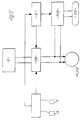
- the block diagram in Fig. 1 which is an example of the horron of the invention, refers to a four wheels vehicle.
- This electrical feed vehicle has a separate propulsion unit for each of the two drive wheels (1); a propulsion unit power supply circuit; an electrical energy recovery unit equipped with several energy recovery generators; a computer (2) fitted with various sensors and control actuators for the control of the vehicle functions.
- the propulsion unit of each drive wheel (1) consists of two electric motors M1 and M2.
- the two motors M1 and M2 are mechanically connected to a common motor shaft.
- Motor M2 or “starter motor” develops its pull-in torque at slow running, at 1000 rpm for example, and is suitable for supplying the push from standstill and the acceleration.
- Motor M2 called the "cruising motor” develops its pull-in torque at a high running, 3000 rpm for example, and as a result is used preferably for normal cruising.
- the alternate or contemporaneous activation or deactivation of the motors M1 and M2 of each propulsion unit is controlled by the computer (2) on the basis of the torque on the common driving shaft measured by the torque sensors (3) and from the acceleration requested by the user; the acceleration request is signalled to computer (2) by the accelerator pedal (4).
- the propulsion units are connected to their respective drive wheels (1) through an adjustable or electrically operated coupling (5), depending on the transmitted torque value.
- the coupling devices (5) are directly controlled by the computer (2) which determines the optimum control or piloting currents or voltages from the torque transmitted from the propulsion units to the respective drive wheel (1).
- the transmitted torque is monitored by the sensors (6).
- the computer (2) also has connections from the steering angle sensors (7), from which computer (2) can determine the difference in angular speed of the drive wheels (1) and controls the motors M1 and M2 of each drive wheel (1) accordingly. This also allows the self-locking differential, flexible coupling and brake balancing functions to be activated.
- the motor M1 and M2 of each propulsion unit is connected to a storage battery (8) consisting of, for example, rechargeable type batteries connected together in a manner that can supply the power feed voltages and currents through a power control unit (9).
- a voltage control device (10), consisting of multiple voltage boosters, is provided between the storage battery (8) and the power control unit (9).
- the power output control is performed by the user through the accelerator pedal (4) which is also connected to the computer (2).
- the braking circuit is hydraulic and is indicated by the number 11.
- the braking devices (12) for each wheel are controlled by the brake pedal (13) through a hydraulic pump (14) and a pressurized fluid reservoir (15).
- An electric shut-off valve (16) is located between the pressurized fluid reservoir (15) and the brake circuit (11), while the reservoir itself is fitted with a pressure sensor (not illustrated). This pressure sensor is also connected to the computer (2).
- Fig. 1 shows an example of a heating pump (17) connected to both the power control unit (9) and computer (2).
- the electrical energy recovery devices are also connected to the power control unit (9). These devices can be of any type, though in this executing example they consist of motors M1 and M2 which, during braking, act as the braking medium, converting the kinetic energy absorbed by one or several photovoltaic cells (18) and shock absorbers (19) into recovered electrical energy.
- the dampers (19) act as linear electric power generators and convert the dynamic effort of the suspension into electrical energy.
- Each motor M1 and M2 of each propulsion unit besides being connected to the storage battery (8), is also connected to a provisional accumulator (20).
- This provisional accumulator (20) is of the electrostatic type and consists of many special condensers, also called super-condensers. These have a very large capacity and a very low internal series resistance.
- the storage battery (8) is connected to each motor M1 and M2 through the control unit (109) of the battery (8).
- the provisional electrostatic accumulator (20) is connected to the motors M1 and M2 through its own control unit (209).
- These two control units (109 and 209) are themselves controlled by the computer (2), to which the motor M1 and M2 power feed level and braking intensity control devices are also connected; such control devices consist of the accelerator (4) and brake pedal or an associated pressure sensor (13).
- the control unit of power (9) illustrated in Fig. 1 is made up of several sub units consisting, at least, of the motor M1 and M2 power feed level control unit, set by the user through the accelerator pedal (4), the battery (8) control unit (109) and the provisional electrostatic accumulator (20) control unit (209).
- the other electrical energy recovery generators (18 and 19) can also be connected to the provisional electrostatic accumulator (20) control unit.
- the computer (2) controls the storage and distribution of the recovered electrical energy as follows: During the deceleration or slow braking phase, the motors M1 and M2 of each propulsion unit are used to absorb the kinetic energy and convert it into recovered electrical energy. This electrical energy is stored in the provisional electrostatic accumulator (20). When the brake pedal (13) or accelerator pedal (4) is operated, the computer (2) receives a braking or deceleration signal isolating the motors M1 and M2 from the storage battery (8) and connects them to the provisional electrostatic accumulator (20) through the respective control units (109 and 209).
- the recovered electrical energy is stored in the electrostatic accumulator (20) rapidly and without any substantial loss, thanks to its characteristics.
- the control unit (209) varies the voltage of the recovered electrical energy in real time in accordance with the variation in the optimum charge voltage, i.e. according to the charge status of the provisional accumulator (20).
- the energy required for a subsequent acceleration or starting phase is usually taken, either all or part, from the provisional accumulator (20), thus avoiding the energy leaks or losses caused in traditional accumulators by excessive storage time.
- the computer (2) maintains this connection between the provisional electrostatic accumulator (20) and the motors M1 and M2 until the charge level in the accumulator has reached a predetermined minimum level. When this minimum level is reached, the computer (2) isolates the provisional electrostatic accumulator (20) from the motors M1 and M2 and connects them to the storage battery (8). The switching of the motors M1 and M2 between the storage battery (8) and the provisional electrostatic accumulator (20) takes place during each deceleration or braking phase when the predetermined minimum charge level of the provisional electrostatic accumulator (20) is reached.
- a further characteristic of the invention comes to light during harsh braking, when the computer (2) activates the hydraulic braking system (11) at the same time as the previously mentioned generator function of the motors M1 and M2. With this system, a substantial braking force is obtained similar, in certain respects, to a progressive braking system on a conventional vehicle with an internal combustion engine.
- the braking intensity is signalled to the computer (2) on the basis of the pressure on the brake pedal (13).
- the motors M1 and M2 are automatically switched from the provisional electrostatic accumulator (20) to the storage battery (8) if the charge level of the accumulator (20) itself is not above the preset minimum. Any charge losses can be compensated for by further electrical energy recovery devices (18 and 19).
- the quantity of recovered electrical energy stored in the provisional accumulator (20) can reach a preset maximum level.
- the invention ensures that the computer (2) sends any extra electrical energy supplied by the motors M1 and M2 directly to the storage battery (8) of the primary power source.
- a control unit can be provided (not illustrated in detail) to vary the voltage of the recovered energy in accordance with the charge level of the primary power source battery (8), thus optimizing the storage of the recovered energy.
Landscapes
- Engineering & Computer Science (AREA)
- Power Engineering (AREA)
- Transportation (AREA)
- Mechanical Engineering (AREA)
- Electric Propulsion And Braking For Vehicles (AREA)
- Arrangement Or Mounting Of Propulsion Units For Vehicles (AREA)
- Control Of Eletrric Generators (AREA)
- Regulating Braking Force (AREA)
- Charge And Discharge Circuits For Batteries Or The Like (AREA)
Applications Claiming Priority (2)
| Application Number | Priority Date | Filing Date | Title |
|---|---|---|---|
| IT12555A IT1241908B (it) | 1990-11-30 | 1990-11-30 | Metodo e dispositivo per la generazione, la gestione e l'utilizzo d' energia elettrica di recupero, in particolare nei veicoli ad alimentazione elettrica |
| IT1255590 | 1990-11-30 |
Publications (1)
| Publication Number | Publication Date |
|---|---|
| EP0488271A1 true EP0488271A1 (en) | 1992-06-03 |
Family
ID=11141551
Family Applications (1)
| Application Number | Title | Priority Date | Filing Date |
|---|---|---|---|
| EP91120365A Withdrawn EP0488271A1 (en) | 1990-11-30 | 1991-11-28 | Method and device for the generation, control and use of recovered electrical energy in particular in electrical feed vehicles |
Country Status (9)
| Country | Link |
|---|---|
| EP (1) | EP0488271A1 (it) |
| BG (1) | BG95552A (it) |
| BR (1) | BR9105204A (it) |
| CA (1) | CA2056654A1 (it) |
| CS (1) | CS363091A3 (it) |
| HU (1) | HUT59631A (it) |
| IT (1) | IT1241908B (it) |
| PL (1) | PL292596A1 (it) |
| RO (1) | RO109286B1 (it) |
Cited By (1)
| Publication number | Priority date | Publication date | Assignee | Title |
|---|---|---|---|---|
| FR2757806A1 (fr) * | 1996-12-26 | 1998-07-03 | Renault | Dispositif d'alimentation electrique d'un moteur electrique de vehicule |
Citations (6)
| Publication number | Priority date | Publication date | Assignee | Title |
|---|---|---|---|---|
| US3548275A (en) * | 1967-10-03 | 1970-12-15 | Tokyo Shibaura Electric Co | Control devices for electric motors |
| US4218624A (en) * | 1977-05-31 | 1980-08-19 | Schiavone Edward L | Electrical vehicle and method |
| DE3602544A1 (de) * | 1986-01-29 | 1987-07-30 | Walter Schopf | Elektromaschinen-gyro-hybridantrieb fuer kfz |
| WO1990001828A1 (en) * | 1988-08-08 | 1990-02-22 | Digimoto Of Sweden Ab | A method for retarding an induction motor |
| US4908553A (en) * | 1988-12-20 | 1990-03-13 | Eaton Corporation | Magnetic regenerative braking system |
| EP0418995A1 (en) * | 1989-09-21 | 1991-03-27 | Isuzu Motors Limited | Energy recovery system for motor vehicle |
-
1990
- 1990-11-30 IT IT12555A patent/IT1241908B/it active IP Right Grant
-
1991
- 1991-11-28 EP EP91120365A patent/EP0488271A1/en not_active Withdrawn
- 1991-11-29 CS CS913630A patent/CS363091A3/cs unknown
- 1991-11-29 RO RO148861A patent/RO109286B1/ro unknown
- 1991-11-29 BR BR919105204A patent/BR9105204A/pt unknown
- 1991-11-29 HU HU913742A patent/HUT59631A/hu unknown
- 1991-11-29 CA CA002056654A patent/CA2056654A1/en not_active Abandoned
- 1991-11-29 PL PL29259691A patent/PL292596A1/xx unknown
- 1991-11-29 BG BG095552A patent/BG95552A/bg unknown
Patent Citations (6)
| Publication number | Priority date | Publication date | Assignee | Title |
|---|---|---|---|---|
| US3548275A (en) * | 1967-10-03 | 1970-12-15 | Tokyo Shibaura Electric Co | Control devices for electric motors |
| US4218624A (en) * | 1977-05-31 | 1980-08-19 | Schiavone Edward L | Electrical vehicle and method |
| DE3602544A1 (de) * | 1986-01-29 | 1987-07-30 | Walter Schopf | Elektromaschinen-gyro-hybridantrieb fuer kfz |
| WO1990001828A1 (en) * | 1988-08-08 | 1990-02-22 | Digimoto Of Sweden Ab | A method for retarding an induction motor |
| US4908553A (en) * | 1988-12-20 | 1990-03-13 | Eaton Corporation | Magnetic regenerative braking system |
| EP0418995A1 (en) * | 1989-09-21 | 1991-03-27 | Isuzu Motors Limited | Energy recovery system for motor vehicle |
Cited By (1)
| Publication number | Priority date | Publication date | Assignee | Title |
|---|---|---|---|---|
| FR2757806A1 (fr) * | 1996-12-26 | 1998-07-03 | Renault | Dispositif d'alimentation electrique d'un moteur electrique de vehicule |
Also Published As
| Publication number | Publication date |
|---|---|
| CA2056654A1 (en) | 1992-05-31 |
| IT9012555A0 (it) | 1990-11-30 |
| BR9105204A (pt) | 1992-07-21 |
| IT9012555A1 (it) | 1992-06-01 |
| HUT59631A (en) | 1992-06-29 |
| HU913742D0 (en) | 1992-03-30 |
| IT1241908B (it) | 1994-02-01 |
| BG95552A (bg) | 1993-12-24 |
| PL292596A1 (en) | 1993-01-11 |
| RO109286B1 (ro) | 1995-01-30 |
| CS363091A3 (en) | 1992-06-17 |
Similar Documents
| Publication | Publication Date | Title |
|---|---|---|
| US7004273B1 (en) | Hybrid electric vehicle | |
| US6484830B1 (en) | Hybrid electric vehicle | |
| US7252165B1 (en) | Hybrid electric vehicle | |
| US5318142A (en) | Hybrid drive system | |
| CA2538775C (en) | Methods of operating a series hybrid vehicle | |
| KR100361041B1 (ko) | 하이브리드파워트레인차량및그의제어방법 | |
| US6054844A (en) | Control method and apparatus for internal combustion engine electric hybrid vehicles | |
| US7096985B2 (en) | Vehicle with a super-capacitor for recovery of energy on braking | |
| US8880258B2 (en) | Hybrid powertrain control | |
| CA2588092C (en) | Regeneration and brake management system | |
| US7937194B2 (en) | System and method for reducing wheel slip and wheel locking in an electric vehicle | |
| US4423794A (en) | Flywheel assisted electro-mechanical drive system | |
| US9827866B2 (en) | Vehicle control system for an at least partially electrically operated vehicle | |
| CA2260715A1 (en) | Control system for hybrid vehicle | |
| MX2014002161A (es) | Vehiculo electrico hibrido. | |
| JP2003009311A (ja) | ハイブリッド駆動システムの回生減速技術 | |
| US20200369259A1 (en) | Hybrid powertrains | |
| GB2470478A (en) | Electromechanical hybrid propulsion system for road vehicles | |
| WO2013075139A1 (en) | Hybrid powertrain control | |
| JP3651448B2 (ja) | 回生装置の制御装置 | |
| Kroics et al. | Supercapacitor based storage system for efficiency improvement of lead-acid powered light electric vehicle | |
| US6877575B2 (en) | Method and apparatus for controlling the speed of an engine within a hybrid electric vehicle | |
| IE53629B1 (en) | Device for recovering the kinetic energy of a motor vehicle during braking and exploiting same during speeding up | |
| US20070012493A1 (en) | Dual hybrid propulsion system | |
| EP0488271A1 (en) | Method and device for the generation, control and use of recovered electrical energy in particular in electrical feed vehicles |
Legal Events
| Date | Code | Title | Description |
|---|---|---|---|
| PUAI | Public reference made under article 153(3) epc to a published international application that has entered the european phase |
Free format text: ORIGINAL CODE: 0009012 |
|
| AK | Designated contracting states |
Kind code of ref document: A1 Designated state(s): AT BE CH DE DK ES FR GB GR LI LU NL SE |
|
| STAA | Information on the status of an ep patent application or granted ep patent |
Free format text: STATUS: THE APPLICATION IS DEEMED TO BE WITHDRAWN |
|
| 18D | Application deemed to be withdrawn |
Effective date: 19921204 |