EP0488158A2 - Safety device for piezoelectric gas lighter - Google Patents
Safety device for piezoelectric gas lighter Download PDFInfo
- Publication number
- EP0488158A2 EP0488158A2 EP91120169A EP91120169A EP0488158A2 EP 0488158 A2 EP0488158 A2 EP 0488158A2 EP 91120169 A EP91120169 A EP 91120169A EP 91120169 A EP91120169 A EP 91120169A EP 0488158 A2 EP0488158 A2 EP 0488158A2
- Authority
- EP
- European Patent Office
- Prior art keywords
- stopper member
- actuator cap
- projection
- safety device
- lighter
- Prior art date
- Legal status (The legal status is an assumption and is not a legal conclusion. Google has not performed a legal analysis and makes no representation as to the accuracy of the status listed.)
- Granted
Links
- 239000007789 gas Substances 0.000 claims abstract description 25
- 230000000994 depressogenic effect Effects 0.000 claims abstract description 12
- 239000002737 fuel gas Substances 0.000 claims abstract description 11
- 210000003811 finger Anatomy 0.000 description 13
- 210000003813 thumb Anatomy 0.000 description 9
- 230000002411 adverse Effects 0.000 description 4
- 230000000881 depressing effect Effects 0.000 description 1
- 239000012858 resilient material Substances 0.000 description 1
Images


Classifications
-
- F—MECHANICAL ENGINEERING; LIGHTING; HEATING; WEAPONS; BLASTING
- F23—COMBUSTION APPARATUS; COMBUSTION PROCESSES
- F23Q—IGNITION; EXTINGUISHING-DEVICES
- F23Q2/00—Lighters containing fuel, e.g. for cigarettes
- F23Q2/16—Lighters with gaseous fuel, e.g. the gas being stored in liquid phase
- F23Q2/164—Arrangements for preventing undesired ignition
-
- F—MECHANICAL ENGINEERING; LIGHTING; HEATING; WEAPONS; BLASTING
- F23—COMBUSTION APPARATUS; COMBUSTION PROCESSES
- F23Q—IGNITION; EXTINGUISHING-DEVICES
- F23Q2/00—Lighters containing fuel, e.g. for cigarettes
- F23Q2/28—Lighters characterised by electrical ignition of the fuel
- F23Q2/285—Lighters characterised by electrical ignition of the fuel with spark ignition
- F23Q2/287—Lighters characterised by electrical ignition of the fuel with spark ignition piezoelectric
Definitions
- This invention relates to a safety device for a piezoelectric gas lighter, and more particularly to a safety device for a piezoelectric gas lighter which prevents depression of an actuator cap of the lighter to prevent inadvertent ignition while the gas lighter is not used.
- the piezoelectric gas lighter has an actuator cap which is mounted on an upper part of the lighter body to be movable up and down, and when the actuator cap is depressed, fuel gas is discharged and an ignition mechanism is actuated to ignite the fuel gas.
- the gas lighter is a convenient tool which can easily be ignited by depression of the actuator cap, it is not preferable in view of safety that those who do not know proper use of the lighter like a child inadvertently ignites it.
- any one of the safety devices as disclosed in Japanese Unexamined Utility Model Publication Nos. 62(1987)-180244, 62(1987)-180247 and 63(1988)-142562, and United States Patent Nos. 4,859,172, 4,786,248 and 4,784,602 has a lock member which prevents depression of the ignition lever.
- the lock member is manually moved between a locking position and a releasing position, and the lock member remains in the releasing position and the safety device cannot function unless the lock member is manually returned to the locking position after it is moved to the releasing position and the the gas lighter is ignited. That is, the lock mechanism must be operated again after it is released and the lighter is used. Otherwise, the lock mechanism cannot function.
- a further improved lock mechanism has been a demand for a further improved lock mechanism.
- the lock member is formed of resilient material and accordingly, the lock member can return to the locking position under its own resiliency after it is moved to the releasing position.
- an auto-return safety device in which the lock member is moved along a linear path to the releasing position, thereby facilitating release of the lock mechanism, and at the same time, it can be held in the releasing position with the finger with which the ignition mechanism is actuated, without using another finger.
- the safety device also has drawbacks for practical use. That is, in the safety device disclosed in the Japanese Unexamined Utility Model Publication No. 1(1989)-178456, the lock member is incorporated in the ignition lever, which is actuated to ignite the lighter, so that the lock member can be moved to the releasing position with the thumb for operating the ignition lever, and the ignition lever is actuated with the thumb after the lock member is moved to the releasing position with the thumb.
- the safety device release of the lock mechanism is facilitated.
- the safety device is disadvantageous in that when the ignition lever is actuated with the thumb after the lock member is moved to the releasing position with the same finger, the lock member can be inadvertently released from the thumb and can return to the locking position. Accordingly, also in the safety device, the lock member cannot be steadily released, which adversely affects ease of releasing the lock mechanism in the gas lighter which is generally operated with a single finger, e.g. the thumb, and leads to different results depending on persons who use the lighter as in the preceding examples.
- any one of the conventional child resistant safety device has drawbacks for practical use, and accordingly there has been a demand for a child resistant safety device which has an enhanced safety and is easy to handle.
- the primary object of the present invention is to provide a safety device for a piezoelectric gas lighter which is excellent both in ease of handling and in safety function and which has an auto-return lock mechanism which can be automatically restored without operation after it is released and the lighter is ignited.
- a safety device for a piezoelectric gas lighter having an actuator cap which is mounted on an upper part of a lighter body to be movable up and down between upper and lower positions relative to the lighter body and is urged to the upper position, the actuator cap being depressed toward the lower position to discharge fuel gas stored in a reservoir provided in the lighter body and to actuate an ignition mechanism to ignite the fuel gas
- said safety device comprising a projection which is provided on said upper part of the lighter body, a stopper member which is mounted on said actuator cap so that it can be movable relative to the actuator cap along a linear path between a locking position where a part of the stopper member is aligned with the projection and interferes with the projection to prevent downward movement of the actuator cap and a releasing position where said part of the stopper member is out of alignment with said projection and permits downward movement of the actuator cap and so that the actuator cap can be depressed by pushing downward the stopper member, an urging means which urges the stopper member to the locking position, and
- the stopper member prevents depression of the actuator cap and does not permit inadvertent ignition of the lighter while the gas lighter is not used, and at the same time, it is automatically returned to the locking position after it is moved to the releasing position to permit ignition and the actuator cap returns to the original position after ignition.
- the stopper member since the stopper member is linearly moved between the locking position and the releasing position, it can be easily operated.
- a top portion 1 of a lighter body has a recess 100 and an actuator cap 2 is slidably received in the recess 100 to be moved downward into the recess 100 and upward out of the recess 100.
- the actuator cap 2 is urged upward by a spring (not shown).
- a piezoelectric ignition mechanism (not shown) which is also provided in the lighter body is actuated to ignite the fuel gas.
- a semi-cylindrical projection 1a is formed on the top portion 1 to project inward of the recess 100, and a stopper member 3 is mounted on the actuator cap 2 to be movable between a locking position ( Figure 1) where it abuts against the projection 1a and prevents depression of the actuator cap 2 and a releasing position ( Figure 2) where it does not interfere with the projection 1a and permits depression of the actuator cap 2.
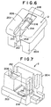
- FIG. 6 and 7 comprises a head portion 202 and a leg portion 204 which extends downward from the head portion 202.
- the leg portion 204 is slightly smaller in size than the recess 100 of the top portion 1 of the lighter body and is slidably received in the recess 100 while the head portion 202 is larger than the leg portion 204 and is substantially equal to the top portion 1 of the lighter body.
- a recess 206 is formed in the head portion 202 of the actuator cap 2 and a slit 208 is formed in the front side (the left side as seen in Figure 1) to extend from the lower surface of the leg portion 204 to the upper surface of the head portion 202.
- the upper end of the slit 208 is smaller than the recess 206 in width, whereby a pair of shoulders 210 facing upward are formed on opposite sides of the upper end of the slit 208.
- the lower end portion of the slit 208 is enlarged to form a pair of shoulders 212 facing downward.
- a semi-cylindrical spring seat 214 is formed in the recess 206 behind the slit 208, and a pair of recesses 216 which are L-shaped in cross-section as clearly shown in Figure 7 are formed on opposite sides of the spring seat 214.
- a spring retaining wall portion 218 is formed on the rear end of the spring seat 214.
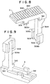
- the stopper member 3 comprises a head portion 300 which extends horizontally and has a knurled upper surface 302, and a leg portion 304 which extends downward from the front end of the head portion 300.
- a pair of tab portions 306 each having a barb portion 306a extends downward from the head portion 300 on opposite sides thereof.
- the leg portion 304 is smaller than the head portion 300 in width and a pair of shoulders 310 facing downward are formed on opposite sides of the leg portion 304.
- a pair of engagement portions 308 each having a barb portion 308a are provided on opposite sides of the lower end portion of the leg portion 304.
- a recess 312 is formed on lower surface of the head portion 300 to accommodate a coil spring 3a placed on the spring seat 214 of the actuator cap 2 as shown in Figures 4 and 5.
- the stopper member 3 With the spring 3a placed on the spring seat 214 of the actuator cap 2, the stopper member 3 is incorporated in the actuator cap 2.
- the tab portions 306 of the stopper member 3 are forced into the recesses 216 of the actuator cap 2 and the engagement portions 308 are forced into the lower end portion of the slit 208 of the actuator cap 2.
- the barb portion 306a of each tab portion 306 engages with the shoulder of the L-shaped recess 216, whereby the tab portions 306 are prevented from being drawn upward out from the recesses 213 though the tab portions 306 is permitted to slide along the recesses 216.
- the barb portions 308a of the engagement portions 308 engage with the rear face of the wall portions on opposite sides of the lower end portion of the slit 208, whereby the engagement portions 308 are prevented from being drawn out from the slit 208 though the engagement portions 308 are permitted to slide vertically along the slit 208.
- the coil spring 3a is compressed between the inner surface 304a of the leg portion 304 and the spring retaining wall portion 218, thereby urging the stopper member 3 to the locking position shown in Figure 1, the shoulders 310 on opposite sides of the leg portion 304 rest on the shoulders 210 on opposite sides of the slit 208, the upper surfaces of the engagement portions 308 are opposed to 212 on opposite sides of the lower end portion of the slit 208, and the knurled upper surface 302 of the head portion 300 of the stopper member 3 is substantially flush with the upper surface of the head portion 202 of the actuator cap 2.
- the stopper member 3 can be moved to the releasing position shown in Figure 2 with the finger for depressing the actuator cap 2 overcoming the force of the spring 3a. In the releasing position, the leg portion 304 of the stopper member 3 is out of alignment with the projection 1a, and accordingly the stopper member 3 cannot interfere with the projection 1a even if the actuator cap 2 is moved downward and permits depression of the actuator cap 2 (See Figures 3 and 5).
- the stopper member 3 When the actuator cap 2 is released after depression, the stopper member 3 is also released and is pushed toward the locking position by the spring 3a. However the stopper member 3 cannot return to the locking position until the actuator cap 2 completely returns to the original position since the leg portion 304 abuts against and slides on the inner surface of the projection 1a.
- a plate spring or the like may be used instead of the coil spring 3a.
- the stopper member 3 When the lighter is used, the stopper member 3 is pushed to the releasing position shown in Figure 2 by a finger. In the releasing position, the stopper member 3 does not interfere with the projection 1a and accordingly the actuator cap 2 can be depressed to discharge fuel gas and to actuate the piezoelectric ignition mechanism.
- the stopper member 3 When the actuator cap 2 is released, the stopper member 3 tries to return to the locking position under the force of the spring 3a upon release of the actuator cap 2. However since the leg portion 304 of the stopper member 3 abuts against the inner surface of the projection 1a, the stopper member 3 cannot return to the locking position until the actuator cap 2 moves upward sufficiently high.
- the stopper member 3 prevents depression of the actuator cap 2 and does not permit inadvertent ignition of the lighter while the gas lighter is not used, and at the same time, it is automatically returned to the locking position after it is moved to the releasing position to permit ignition and the actuator cap 2 returns to the original position after ignition.
- the embodiment described above is just an example and may be variously modified.
- the stopper member 3 is slidable back and forth (left and right in Figure 4) relative to the actuator cap 2, it may be slidable in the transverse direction of the actuator cap 2.
- the projection 1a is semi-cylindrical in shape, it may be a rectangular prism, a triangular prism or the like. Further the projection 1a need not abut against the lower surface of the stopper member 3 but may abut against other part of the same such as a projection or a shoulder portion formed on the stopper member 3.
Landscapes
- Engineering & Computer Science (AREA)
- Chemical & Material Sciences (AREA)
- Combustion & Propulsion (AREA)
- Mechanical Engineering (AREA)
- General Engineering & Computer Science (AREA)
- Lighters Containing Fuel (AREA)
Abstract
Description
- This invention relates to a safety device for a piezoelectric gas lighter, and more particularly to a safety device for a piezoelectric gas lighter which prevents depression of an actuator cap of the lighter to prevent inadvertent ignition while the gas lighter is not used.
- The piezoelectric gas lighter has an actuator cap which is mounted on an upper part of the lighter body to be movable up and down, and when the actuator cap is depressed, fuel gas is discharged and an ignition mechanism is actuated to ignite the fuel gas. Though the gas lighter is a convenient tool which can easily be ignited by depression of the actuator cap, it is not preferable in view of safety that those who do not know proper use of the lighter like a child inadvertently ignites it.
- Accordingly, there has been a demand for a socalled child resistant gas lighter which cannot be inadvertently ignited by children or the like.
- There have been proposed various kinds of child resistant gas lighter. Most of the safety devices built in these child resistant gas lighter have a lock mechanism which prevents depression of the ignition lever and must be released to allow the ignition lever to be depressed. However, any type of the conventional child resistant gas lighter has drawbacks in use and is desired to be improved for practical use.
- For example, any one of the safety devices as disclosed in Japanese Unexamined Utility Model Publication Nos. 62(1987)-180244, 62(1987)-180247 and 63(1988)-142562, and United States Patent Nos. 4,859,172, 4,786,248 and 4,784,602 has a lock member which prevents depression of the ignition lever. The lock member is manually moved between a locking position and a releasing position, and the lock member remains in the releasing position and the safety device cannot function unless the lock member is manually returned to the locking position after it is moved to the releasing position and the the gas lighter is ignited. That is, the lock mechanism must be operated again after it is released and the lighter is used. Otherwise, the lock mechanism cannot function. Thus there has been a demand for a further improved lock mechanism.
- There has been proposed a safety device having a so-called auto-return function for automatically returning the lock member (which prevents depression of the ignition lever) to the locking position in response to the igniting operation of the gas lighter after movement of the lock member to the releasing position. For example, those disclosed in United States Patent Nos. 5,002,482 and 3,898,031, and Japanese Unexamined Patent Publication No. 3(1991)-25215 have such an auto-return function. However, either of these safety devices has drawbacks for practical use that release of the lock mechanism involves a motion of a finger along an L-shaped path, which adversely affects ease of releasing the lock mechanism in the gas lighter which is generally operated with a single finger, e.g. the thumb, and leads to different results depending on persons who use the lighter. Further, in the safety device disclosed in the former patent publication, the lock member is formed of resilient material and accordingly, the lock member can return to the locking position under its own resiliency after it is moved to the releasing position.
- Though there have been proposed safety devices in which the lock mechanism is released by a motion of a finger along a path in the form of a simple line. not L-shaped, any one of them has drawbacks for practical use. For example, in the safety device disclosed in Japanese Patent publication of Translated Version (PCT) No. 3(1991)-501647, a part of a lock member which is formed of spring is moved along an arcuate path to the releasing position and held there. However, in the safety device, the arrangement for guiding release of the spring-like lock member is not satisfactory and accordingly the lock member cannot be steadily released, which adversely affects ease of releasing the lock mechanism in the gas lighter which is generally operated with a single finger, e.g. the thumb, and leads to different results depending on persons who use the lighter as in the preceding example. Further, since the lock member is formed of spring, the lock member can deform to cause failure of the lock mechanism after repeated use of the lighter.
- In the safety device disclosed in United States Patent No. 4,832,596, the lock member is moved along a linear path to the releasing position but it automatically returns to the locking position unless it is held with a finger other than the finger with which the ignition mechanism is actuated. Accordingly, in the safety device, the lock member cannot be steadily released, which adversely affects ease of releasing the lock mechanism in the gas lighter which is generally operated with a single finger, e.g. the thumb, and leads to different results depending on persons who use the lighter as in the preceding examples.
- In order to overcome such problems, there has been proposed an auto-return safety device in which the lock member is moved along a linear path to the releasing position, thereby facilitating release of the lock mechanism, and at the same time, it can be held in the releasing position with the finger with which the ignition mechanism is actuated, without using another finger. However, the safety device also has drawbacks for practical use. That is, in the safety device disclosed in the Japanese Unexamined Utility Model Publication No. 1(1989)-178456, the lock member is incorporated in the ignition lever, which is actuated to ignite the lighter, so that the lock member can be moved to the releasing position with the thumb for operating the ignition lever, and the ignition lever is actuated with the thumb after the lock member is moved to the releasing position with the thumb. Thus in the safety device, release of the lock mechanism is facilitated. However, the safety device is disadvantageous in that when the ignition lever is actuated with the thumb after the lock member is moved to the releasing position with the same finger, the lock member can be inadvertently released from the thumb and can return to the locking position. Accordingly, also in the safety device, the lock member cannot be steadily released, which adversely affects ease of releasing the lock mechanism in the gas lighter which is generally operated with a single finger, e.g. the thumb, and leads to different results depending on persons who use the lighter as in the preceding examples.
- As can be understood from the description above, any one of the conventional child resistant safety device has drawbacks for practical use, and accordingly there has been a demand for a child resistant safety device which has an enhanced safety and is easy to handle.
- In view of the foregoing observations and description, the primary object of the present invention is to provide a safety device for a piezoelectric gas lighter which is excellent both in ease of handling and in safety function and which has an auto-return lock mechanism which can be automatically restored without operation after it is released and the lighter is ignited.
- In accordance with the present invention, there is provided a safety device for a piezoelectric gas lighter having an actuator cap which is mounted on an upper part of a lighter body to be movable up and down between upper and lower positions relative to the lighter body and is urged to the upper position, the actuator cap being depressed toward the lower position to discharge fuel gas stored in a reservoir provided in the lighter body and to actuate an ignition mechanism to ignite the fuel gas, said safety device comprising a projection which is provided on said upper part of the lighter body, a stopper member which is mounted on said actuator cap so that it can be movable relative to the actuator cap along a linear path between a locking position where a part of the stopper member is aligned with the projection and interferes with the projection to prevent downward movement of the actuator cap and a releasing position where said part of the stopper member is out of alignment with said projection and permits downward movement of the actuator cap and so that the actuator cap can be depressed by pushing downward the stopper member, an urging means which urges the stopper member to the locking position, and a holding means which holds the stopper member in the releasing position when the actuator cap is below said upper position.
- In the safety device in accordance with the present invention, the stopper member prevents depression of the actuator cap and does not permit inadvertent ignition of the lighter while the gas lighter is not used, and at the same time, it is automatically returned to the locking position after it is moved to the releasing position to permit ignition and the actuator cap returns to the original position after ignition. Thus a highly safe gas lighter having an auto-return function in which the lock mechanism is automatically restored without operation after it is released and the lighter is ignited can be realized.
- Further, in the gas lighter in accordance with the present invention, since the stopper member is linearly moved between the locking position and the releasing position, it can be easily operated.
-
- Figure 1 is a perspective view showing an important part of a safety device in the locking state in accordance with an embodiment of the present invention,
- Figure 2 is a perspective view showing the same but in the releasing position,
- Figure 3 is a perspective view showing the same but with the actuator cap depressed,
- Figure 4 is a side cross-sectional view showing the same in the locking position,
- Figure 5 is a side cross-sectional view showing the same with the actuator cap depressed,
- Figure 6 is a perspective view showing the actuator cap,
- Figure 7 is a perspective view of the actuator cap as viewed from below,
- Figure 8 is a perspective view showing the stopper member, and
- Figure 9 is a perspective view of the stopper member as viewed from below.
- In Figures 1 to 9, a top portion 1 of a lighter body has a
recess 100 and anactuator cap 2 is slidably received in therecess 100 to be moved downward into therecess 100 and upward out of therecess 100. Theactuator cap 2 is urged upward by a spring (not shown). When theactuator cap 2 is depressed into therecess 100, fuel gas stored in a reservoir (not shown) provided in the lighter body is discharged and at the same time, a piezoelectric ignition mechanism (not shown) which is also provided in the lighter body is actuated to ignite the fuel gas. - A semi-cylindrical projection 1a is formed on the top portion 1 to project inward of the
recess 100, and astopper member 3 is mounted on theactuator cap 2 to be movable between a locking position (Figure 1) where it abuts against the projection 1a and prevents depression of theactuator cap 2 and a releasing position (Figure 2) where it does not interfere with the projection 1a and permits depression of theactuator cap 2. - As shown in Figures 6 and 7 comprises a
head portion 202 and aleg portion 204 which extends downward from thehead portion 202. Theleg portion 204 is slightly smaller in size than therecess 100 of the top portion 1 of the lighter body and is slidably received in therecess 100 while thehead portion 202 is larger than theleg portion 204 and is substantially equal to the top portion 1 of the lighter body. Arecess 206 is formed in thehead portion 202 of theactuator cap 2 and aslit 208 is formed in the front side (the left side as seen in Figure 1) to extend from the lower surface of theleg portion 204 to the upper surface of thehead portion 202. The upper end of theslit 208 is smaller than therecess 206 in width, whereby a pair ofshoulders 210 facing upward are formed on opposite sides of the upper end of theslit 208. The lower end portion of theslit 208 is enlarged to form a pair ofshoulders 212 facing downward. Asemi-cylindrical spring seat 214 is formed in therecess 206 behind theslit 208, and a pair ofrecesses 216 which are L-shaped in cross-section as clearly shown in Figure 7 are formed on opposite sides of thespring seat 214. A springretaining wall portion 218 is formed on the rear end of thespring seat 214. - As shown in Figures 8 and 9, the
stopper member 3 comprises ahead portion 300 which extends horizontally and has a knurledupper surface 302, and aleg portion 304 which extends downward from the front end of thehead portion 300. A pair oftab portions 306 each having abarb portion 306a extends downward from thehead portion 300 on opposite sides thereof. Theleg portion 304 is smaller than thehead portion 300 in width and a pair ofshoulders 310 facing downward are formed on opposite sides of theleg portion 304. A pair ofengagement portions 308 each having abarb portion 308a are provided on opposite sides of the lower end portion of theleg portion 304. Further, arecess 312 is formed on lower surface of thehead portion 300 to accommodate a coil spring 3a placed on thespring seat 214 of theactuator cap 2 as shown in Figures 4 and 5. - With the spring 3a placed on the
spring seat 214 of theactuator cap 2, thestopper member 3 is incorporated in theactuator cap 2. When thestopper member 3 is incorporated in theactuator cap 2, thetab portions 306 of thestopper member 3 are forced into therecesses 216 of theactuator cap 2 and theengagement portions 308 are forced into the lower end portion of theslit 208 of theactuator cap 2. When thetab portions 306 are once forced into therecesses 216, thebarb portion 306a of eachtab portion 306 engages with the shoulder of the L-shapedrecess 216, whereby thetab portions 306 are prevented from being drawn upward out from the recesses 213 though thetab portions 306 is permitted to slide along therecesses 216. Similarly when theengagement portions 308 are once forced into the lower end portion of theslit 208 of theactuator cap 2, thebarb portions 308a of theengagement portions 308 engage with the rear face of the wall portions on opposite sides of the lower end portion of theslit 208, whereby theengagement portions 308 are prevented from being drawn out from theslit 208 though theengagement portions 308 are permitted to slide vertically along theslit 208. In this state, the coil spring 3a is compressed between theinner surface 304a of theleg portion 304 and the spring retainingwall portion 218, thereby urging thestopper member 3 to the locking position shown in Figure 1, theshoulders 310 on opposite sides of theleg portion 304 rest on theshoulders 210 on opposite sides of theslit 208, the upper surfaces of theengagement portions 308 are opposed to 212 on opposite sides of the lower end portion of theslit 208, and the knurledupper surface 302 of thehead portion 300 of thestopper member 3 is substantially flush with the upper surface of thehead portion 202 of theactuator cap 2. - In the locking position, the
lower surface 311 of thestopper member 3 abuts against the upper surface of the projection 1a and depression of theactuator cap 2 is prevented. - The
stopper member 3 can be moved to the releasing position shown in Figure 2 with the finger for depressing theactuator cap 2 overcoming the force of the spring 3a. In the releasing position, theleg portion 304 of thestopper member 3 is out of alignment with the projection 1a, and accordingly thestopper member 3 cannot interfere with the projection 1a even if theactuator cap 2 is moved downward and permits depression of the actuator cap 2 (See Figures 3 and 5). - When the
actuator cap 2 is released after depression, thestopper member 3 is also released and is pushed toward the locking position by the spring 3a. However thestopper member 3 cannot return to the locking position until theactuator cap 2 completely returns to the original position since theleg portion 304 abuts against and slides on the inner surface of the projection 1a. - As the means for urging the
stopper member 3 to the locking position, a plate spring or the like may be used instead of the coil spring 3a. - The operation of the safety device of this embodiment will be described in detail, hereinbelow.
- While the lighter is not used, the
stopper member 3 is held in the locking position shown in Figures 1 and 4 where it prevents depression of theactuator cap 2. In this state, ignition of the lighter is disabled and the lighter cannot be inadvertently ignited by children or the like. - When the lighter is used, the
stopper member 3 is pushed to the releasing position shown in Figure 2 by a finger. In the releasing position, thestopper member 3 does not interfere with the projection 1a and accordingly theactuator cap 2 can be depressed to discharge fuel gas and to actuate the piezoelectric ignition mechanism. - When the
actuator cap 2 is released, thestopper member 3 tries to return to the locking position under the force of the spring 3a upon release of theactuator cap 2. However since theleg portion 304 of thestopper member 3 abuts against the inner surface of the projection 1a, thestopper member 3 cannot return to the locking position until theactuator cap 2 moves upward sufficiently high. - As can be understood from the description above, in the safety device of this embodiment, the
stopper member 3 prevents depression of theactuator cap 2 and does not permit inadvertent ignition of the lighter while the gas lighter is not used, and at the same time, it is automatically returned to the locking position after it is moved to the releasing position to permit ignition and theactuator cap 2 returns to the original position after ignition. Thus a highly safe gas lighter having an auto-return function in which the lock mechanism is automatically restored without operation after it is released and the lighter is ignited can be realized. - Needless to say, the embodiment described above is just an example and may be variously modified. For example, though, in the embodiment described above, the
stopper member 3 is slidable back and forth (left and right in Figure 4) relative to theactuator cap 2, it may be slidable in the transverse direction of theactuator cap 2. - Further though, in the embodiment described above, the projection 1a is semi-cylindrical in shape, it may be a rectangular prism, a triangular prism or the like. Further the projection 1a need not abut against the lower surface of the
stopper member 3 but may abut against other part of the same such as a projection or a shoulder portion formed on thestopper member 3.
Claims (5)
- A safety device for a piezoelectric gas lighter having an actuator cap which is mounted on an upper part of a lighter body to be movable up and down between upper and lower positions relative to the lighter body and is urged to the upper position, the actuator cap being depressed toward the lower position to discharge fuel gas stored in a reservoir provided in the lighter body and to actuate an ignition mechanism to ignite the fuel gas, said safety device comprising
a projection which is provided on said upper part of the lighter body,
a stopper member which is mounted on said actuator cap so that it can be movable relative to the actuator cap along a linear path between a locking position where a part of the stopper member is aligned with the projection and interferes with the projection to prevent downward movement of the actuator cap and a releasing position where said part of the stopper member is out of alignment with said projection and permits downward movement of the actuator cap and so that the actuator cap can be depressed by pushing downward the stopper member,
an urging means which urges the stopper member to the locking position, and
a holding means which holds the stopper member in the releasing position when the actuator cap is below said upper position. - A safety device as defined in Claim 1 in which said stopper member has a leg portion which extends downward and the lower surface of the leg portion rests on the upper surface of said projection to prevent downward movement of the actuator cap.
- A safety device as defined in claims 1 or 2 in which said holding means is an abutment surface which extends downward from the level of the upper surface of the projection facing toward the releasing position of the stopper member and on which the leg portion slides when the actuator cap is moved downward together with the stopper member with the stopper member in the releasing position.
- A safety device as defined in one of the claims 1, 2 or 3 in which said projection has a vertical surface which extends downward facing toward the releasing position of the stopper member and said abutment surface comprises the vertical surface of the projection.
- A safety device as defined in one of the claims 1 to 4 in which said stopper member has a head portion which extends horizontally and said leg portion extends downward from the head portion and the head portion is slidably received in a recess formed on the upper surface of the actuator cap.
Applications Claiming Priority (2)
| Application Number | Priority Date | Filing Date | Title |
|---|---|---|---|
| JP130581/90 | 1990-11-30 | ||
| JP1990130581U JPH0492142U (en) | 1990-11-30 | 1990-11-30 |
Publications (3)
| Publication Number | Publication Date |
|---|---|
| EP0488158A2 true EP0488158A2 (en) | 1992-06-03 |
| EP0488158A3 EP0488158A3 (en) | 1993-01-07 |
| EP0488158B1 EP0488158B1 (en) | 1996-02-14 |
Family
ID=15037641
Family Applications (1)
| Application Number | Title | Priority Date | Filing Date |
|---|---|---|---|
| EP91120169A Expired - Lifetime EP0488158B1 (en) | 1990-11-30 | 1991-11-26 | Safety device for piezoelectric gas lighter |
Country Status (6)
| Country | Link |
|---|---|
| US (1) | US5145358A (en) |
| EP (1) | EP0488158B1 (en) |
| JP (1) | JPH0492142U (en) |
| CA (1) | CA2056338C (en) |
| DE (1) | DE69117143T2 (en) |
| MX (1) | MX9102310A (en) |
Cited By (16)
| Publication number | Priority date | Publication date | Assignee | Title |
|---|---|---|---|---|
| EP0611096A2 (en) * | 1993-02-09 | 1994-08-17 | Masayuki Iwahori | Lighter |
| US5451159A (en) * | 1994-07-14 | 1995-09-19 | Kim; Jin K. | Gas lighter with safety device to prevent release of gas |
| EP0725915A4 (en) * | 1992-10-23 | 1995-09-19 | Bic Corp | Selectively actuatable lighter |
| US5462432A (en) * | 1994-06-17 | 1995-10-31 | Kim; Jin K. | Gas lighter with ignition safety device |
| GB2292448A (en) * | 1994-08-18 | 1996-02-21 | Tokai Corp | Safety device in lighting rods |
| FR2743867A1 (en) * | 1996-01-24 | 1997-07-25 | Cricket Sa | LIGHTER ACTUATED BY A LONGITUDINALLY MOVABLE PUSH BUTTON, CHILD-PROOF |
| US5854530A (en) * | 1996-12-18 | 1998-12-29 | Bic Corporation | Piezoelectric lighter which has a higher level of difficulty for operation |
| US6042367A (en) * | 1994-08-18 | 2000-03-28 | Tokai Corporation | Safety device in lighting rods |
| US6046528A (en) * | 1997-11-03 | 2000-04-04 | Bic Corporation | Selectively actuatable piezoelectric ignition mechanism |
| US6086358A (en) * | 1999-11-04 | 2000-07-11 | Potskhishvili; David Vakhtangovich | Piezoelectric gas lighter with safety device |
| US6093017A (en) * | 1994-08-18 | 2000-07-25 | Tokai Corporation | Safety device in lighting rods |
| US6575735B1 (en) | 1999-08-02 | 2003-06-10 | Flamagas, S.A. | Portable lighter |
| EP1441178A1 (en) * | 2003-01-27 | 2004-07-28 | Lou, Guoliang | Safety and force saving lighter |
| US6840759B2 (en) | 2002-01-04 | 2005-01-11 | Ronson Corporation | Igniter incorporating a safety locking device |
| US7771191B2 (en) | 2006-05-31 | 2010-08-10 | Irwin Industrial Tool Company | Safety mechanism for a torch |
| WO2019134205A1 (en) * | 2018-01-02 | 2019-07-11 | 宁波市洋灵科技有限公司 | Electric arc lighter |
Families Citing this family (55)
| Publication number | Priority date | Publication date | Assignee | Title |
|---|---|---|---|---|
| US5427522A (en) * | 1988-09-02 | 1995-06-27 | Bic Corporation | Selectively actuatable lighter |
| US5435719A (en) * | 1988-09-02 | 1995-07-25 | Bic Corporation | Selectively actuatable lighter |
| JP2784977B2 (en) * | 1992-01-13 | 1998-08-13 | 株式会社東海 | Gas lighter with safety device |
| US5439375A (en) * | 1994-06-16 | 1995-08-08 | American Tectrade Enterprises, Inc. | Child-resistant lockable lighter |
| KR0114876Y1 (en) * | 1995-03-23 | 1998-04-16 | 마고토 이찌가와 | A lighter with safety device |
| CN2224336Y (en) * | 1995-06-23 | 1996-04-10 | 北京市贝斯特实用技术研究所 | Self-locking type gas-lighter with automatic closing function |
| AU1067397A (en) * | 1995-12-04 | 1997-06-27 | Laforest Bic, S.A. | Piezoelectric mechanism for gas lighters with externally closed telescopic body |
| US5839892A (en) * | 1996-03-26 | 1998-11-24 | Hwang; Ing Feng | Electronic lighter with a safety device |
| US5788476A (en) * | 1996-04-30 | 1998-08-04 | Polycity Industrial Ltd | Childproof piezoelectric lighter with sliding mechanism |
| US5829963A (en) * | 1996-06-04 | 1998-11-03 | Modern Royal Co., Ltd. | Gas lighter with safety device |
| US5846069A (en) * | 1996-08-20 | 1998-12-08 | Polycity Industrial Limited | Safety lighter with wheel hood |
| US5980239A (en) * | 1997-09-02 | 1999-11-09 | Bic Corporation | Child resistant lighter |
| US6077070A (en) * | 1997-09-02 | 2000-06-20 | Bic Corporation | Child resistant lighter |
| US6039561A (en) * | 1998-02-23 | 2000-03-21 | Lei; Hou Chong | Safety piezo-electric lighter |
| US6435859B1 (en) | 1998-03-11 | 2002-08-20 | Calico Brands, Inc. | Flint gas lighter with ignition resistant mechanism |
| US5997282A (en) * | 1998-09-29 | 1999-12-07 | Man; Aman Chung Kai | Child-resistant piezo-electric safety lighter |
| US6206689B1 (en) | 1998-10-15 | 2001-03-27 | Bic Corporation | Child resistant lighter |
| US6382960B1 (en) | 1998-10-15 | 2002-05-07 | B I C Corporation | Child resistant lighter |
| US6010328A (en) * | 1999-03-26 | 2000-01-04 | Sung; Kil Yong | Double-trigger child-resistant utility lighter |
| US6238116B1 (en) | 1999-04-30 | 2001-05-29 | Bic Corporation | Foam applicator with wiper insert |
| US6234784B1 (en) * | 1999-07-29 | 2001-05-22 | Yoshinaga Technica Corporation | Portable lighter having igniter device equipped with safety lock mechanism |
| US6146129A (en) * | 1999-11-02 | 2000-11-14 | A.S.G. Enterprise, Inc. | Cigarette lighter safety locking device utilizing a spring biased latch |
| FR2800849B1 (en) | 1999-11-10 | 2002-04-05 | Pollyconcept S A | LIGHTER COMPRISING A SAFETY MECHANISM |
| JP2001141237A (en) | 1999-11-15 | 2001-05-25 | Tokai Corp | Spark ignition type gas lighter |
| US6666678B2 (en) | 1999-12-02 | 2003-12-23 | Calico Brands, Inc. | Multi-button piezoelectric child-resistant cigarette lighter |
| US6095796A (en) * | 1999-12-02 | 2000-08-01 | Sung; Kil Yong | Double-button piezoelectric child-resistant cigarette lighter |
| US6135763A (en) * | 1999-12-20 | 2000-10-24 | Man; Aman Chung Kai | Utility lighter with an automatically locking child-resistant mechanism |
| US6224368B1 (en) * | 2000-01-04 | 2001-05-01 | Aman K. M. Chung | Safety lighter with compound finger pad |
| FR2804749B1 (en) | 2000-02-04 | 2002-07-19 | Pollyconcept S A | PIEZOELECTRIC LIGHTER WITH IMPROVED SECURITY |
| US6428309B1 (en) | 2000-02-22 | 2002-08-06 | Bic Corporation | Utility lighter |
| US6217313B1 (en) * | 2000-07-24 | 2001-04-17 | Ying Wen Luo | Childproof barbecue lighter |
| AU2001278689A1 (en) * | 2000-08-04 | 2002-02-18 | Showa Denko K K | Integrated heat exchanger |
| US6287109B1 (en) * | 2000-08-29 | 2001-09-11 | Hirota & Co., Ltd. | Child-proof locking mechanism for lighter |
| US6916171B2 (en) | 2000-11-03 | 2005-07-12 | Bic Corporation | Multi-mode lighter |
| US7311518B2 (en) * | 2000-11-03 | 2007-12-25 | Bic Corporation | Multi-mode lighter |
| US6488492B2 (en) | 2000-11-03 | 2002-12-03 | Bic Corporation | Multi-mode lighter |
| US6491515B1 (en) | 2000-11-03 | 2002-12-10 | Bic Corporation | Multi-mode lighter |
| US7744368B2 (en) * | 2000-11-03 | 2010-06-29 | Bic Corporation | Multi-mode lighter |
| US6908302B2 (en) | 2000-11-03 | 2005-06-21 | Bic Corporation | Multi-mode lighter |
| US6971870B2 (en) * | 2000-11-03 | 2005-12-06 | Bic Corporation | Multi-mode lighter |
| US6726469B2 (en) | 2000-11-03 | 2004-04-27 | Bic Corporation | Multi-mode lighter |
| US6419479B1 (en) * | 2001-01-18 | 2002-07-16 | Ying Fang Huang | Lighter having a simplified safety lock |
| JP3786052B2 (en) * | 2001-07-16 | 2006-06-14 | 株式会社東海 | Ignition equipment |
| US6506046B1 (en) * | 2001-10-04 | 2003-01-14 | Zhuoye Lighter (Usa) Ltd. | Piezoelectric lighter with safety arrangement |
| CN2548026Y (en) | 2002-04-10 | 2003-04-30 | 黄新华 | Lighter having button guarding piece |
| US6540507B1 (en) * | 2002-05-28 | 2003-04-01 | John Jiin Chung Yang | Piezoelectric lighter with safety lock |
| CN2562087Y (en) * | 2002-08-30 | 2003-07-23 | 浙江大学 | Electronic lighter with lock devices |
| CN2878950Y (en) * | 2006-03-06 | 2007-03-14 | 宁波新海电气股份有限公司 | Cigarette lighter with safety switch |
| US8653942B2 (en) | 2008-08-20 | 2014-02-18 | John Gibson Enterprises, Inc. | Portable biometric lighter |
| US20100099053A1 (en) * | 2008-10-16 | 2010-04-22 | I-Hsuan Lai | Structure of lighter with safety button |
| US20110091825A1 (en) * | 2009-10-16 | 2011-04-21 | Xinhua Huang | Child resistant gas lighter |
| JP5164185B2 (en) * | 2010-08-13 | 2013-03-13 | 株式会社サロメ | Gas writer |
| US9017066B2 (en) * | 2011-04-25 | 2015-04-28 | Zippo Manufacturing Company | Multiple activation contact lighter |
| US10502419B2 (en) | 2017-09-12 | 2019-12-10 | John Gibson Enterprises, Inc. | Portable biometric lighter |
| US11079110B2 (en) | 2018-09-28 | 2021-08-03 | Zippo Manufacturing Company | Childproof ignition device |
Citations (2)
| Publication number | Priority date | Publication date | Assignee | Title |
|---|---|---|---|---|
| EP0345729A2 (en) * | 1988-06-07 | 1989-12-13 | Tokai Corporation | Gaslighter equipped with a locking means to prevent undesired ignition |
| WO1990012254A1 (en) * | 1989-04-07 | 1990-10-18 | Cricket | Child-proof gas lighter |
Family Cites Families (14)
| Publication number | Priority date | Publication date | Assignee | Title |
|---|---|---|---|---|
| US3898031A (en) * | 1974-05-17 | 1975-08-05 | Richard Rusakowicz | Gas fueled safety lighter |
| JPH0629856B2 (en) * | 1986-01-31 | 1994-04-20 | ザ ダウ ケミカル カンパニ− | Fiber-optical probe |
| JPS62180244A (en) * | 1986-02-04 | 1987-08-07 | Ngk Spark Plug Co Ltd | Mixing ratio sensor for alcohol mixed fuel |
| JPS63142562A (en) * | 1986-12-05 | 1988-06-14 | Hitachi Ltd | Cassette loading and unloading device |
| JPH045890Y2 (en) * | 1987-03-09 | 1992-02-19 | ||
| JPH045891Y2 (en) * | 1987-03-09 | 1992-02-19 | ||
| JPH0335975Y2 (en) * | 1987-05-20 | 1991-07-30 | ||
| EP0312627B1 (en) * | 1987-10-21 | 1990-11-28 | Tokai Corporation | Gaslighter equipped with a safety lock |
| JPH01178456A (en) * | 1988-01-06 | 1989-07-14 | Nec Corp | Stepped armature assembly |
| US4832596A (en) * | 1988-04-15 | 1989-05-23 | Morris Sr Glenn H | Child resistant cigarette lighter |
| JPH03501647A (en) * | 1988-07-01 | 1991-04-11 | スィブジェ ソシエテ アノニム | safety lighter |
| US5002482B1 (en) * | 1988-09-02 | 2000-02-29 | Bic Corp | Selectively actuatable lighter |
| ES2016143A6 (en) * | 1989-06-19 | 1990-10-16 | Laforest Sa | Safety mechanisms for lighters |
| JP4082550B2 (en) * | 2000-09-04 | 2008-04-30 | 西川ゴム工業株式会社 | Manhole flexible joint mounting structure and manhole flexible joint |
-
1990
- 1990-11-30 JP JP1990130581U patent/JPH0492142U/ja active Pending
-
1991
- 1991-11-25 US US07/797,300 patent/US5145358A/en not_active Expired - Lifetime
- 1991-11-26 DE DE69117143T patent/DE69117143T2/en not_active Expired - Lifetime
- 1991-11-26 EP EP91120169A patent/EP0488158B1/en not_active Expired - Lifetime
- 1991-11-27 CA CA002056338A patent/CA2056338C/en not_active Expired - Lifetime
- 1991-11-29 MX MX9102310A patent/MX9102310A/en unknown
Patent Citations (2)
| Publication number | Priority date | Publication date | Assignee | Title |
|---|---|---|---|---|
| EP0345729A2 (en) * | 1988-06-07 | 1989-12-13 | Tokai Corporation | Gaslighter equipped with a locking means to prevent undesired ignition |
| WO1990012254A1 (en) * | 1989-04-07 | 1990-10-18 | Cricket | Child-proof gas lighter |
Cited By (24)
| Publication number | Priority date | Publication date | Assignee | Title |
|---|---|---|---|---|
| EP0725915A4 (en) * | 1992-10-23 | 1995-09-19 | Bic Corp | Selectively actuatable lighter |
| EP0725915A1 (en) * | 1992-10-23 | 1996-08-14 | Bic Corporation | Selectively actuatable lighter |
| EP0611096A2 (en) * | 1993-02-09 | 1994-08-17 | Masayuki Iwahori | Lighter |
| EP0611096A3 (en) * | 1993-02-09 | 1996-04-10 | Masayuki Iwahori | Lighter. |
| US5462432A (en) * | 1994-06-17 | 1995-10-31 | Kim; Jin K. | Gas lighter with ignition safety device |
| US5451159A (en) * | 1994-07-14 | 1995-09-19 | Kim; Jin K. | Gas lighter with safety device to prevent release of gas |
| GB2292448A (en) * | 1994-08-18 | 1996-02-21 | Tokai Corp | Safety device in lighting rods |
| DE19530325C5 (en) * | 1994-08-18 | 2004-08-19 | Tokai Corp. | Safety device in ignition rods |
| US6093017A (en) * | 1994-08-18 | 2000-07-25 | Tokai Corporation | Safety device in lighting rods |
| US5697775A (en) * | 1994-08-18 | 1997-12-16 | Tokai Corporation | Safety device in lighting rods |
| US6042367A (en) * | 1994-08-18 | 2000-03-28 | Tokai Corporation | Safety device in lighting rods |
| GB2292448B (en) * | 1994-08-18 | 1999-01-13 | Tokai Corp | Safety device in lighting rods |
| US5885069A (en) * | 1996-01-24 | 1999-03-23 | Cricket S.A. | Lighter |
| WO1997027431A1 (en) * | 1996-01-24 | 1997-07-31 | Cricket S.A. | A lighter |
| FR2743867A1 (en) * | 1996-01-24 | 1997-07-25 | Cricket Sa | LIGHTER ACTUATED BY A LONGITUDINALLY MOVABLE PUSH BUTTON, CHILD-PROOF |
| US5854530A (en) * | 1996-12-18 | 1998-12-29 | Bic Corporation | Piezoelectric lighter which has a higher level of difficulty for operation |
| US6046528A (en) * | 1997-11-03 | 2000-04-04 | Bic Corporation | Selectively actuatable piezoelectric ignition mechanism |
| US6575735B1 (en) | 1999-08-02 | 2003-06-10 | Flamagas, S.A. | Portable lighter |
| US6086358A (en) * | 1999-11-04 | 2000-07-11 | Potskhishvili; David Vakhtangovich | Piezoelectric gas lighter with safety device |
| US6840759B2 (en) | 2002-01-04 | 2005-01-11 | Ronson Corporation | Igniter incorporating a safety locking device |
| EP1441178A1 (en) * | 2003-01-27 | 2004-07-28 | Lou, Guoliang | Safety and force saving lighter |
| US7771191B2 (en) | 2006-05-31 | 2010-08-10 | Irwin Industrial Tool Company | Safety mechanism for a torch |
| DE102007024923B4 (en) * | 2006-05-31 | 2010-10-28 | Irwin Industrial Tool Co. | Safety mechanism for a burner |
| WO2019134205A1 (en) * | 2018-01-02 | 2019-07-11 | 宁波市洋灵科技有限公司 | Electric arc lighter |
Also Published As
| Publication number | Publication date |
|---|---|
| MX9102310A (en) | 1992-06-01 |
| CA2056338A1 (en) | 1992-05-31 |
| JPH0492142U (en) | 1992-08-11 |
| US5145358A (en) | 1992-09-08 |
| DE69117143T2 (en) | 1996-09-19 |
| DE69117143D1 (en) | 1996-03-28 |
| EP0488158A3 (en) | 1993-01-07 |
| CA2056338C (en) | 1995-10-10 |
| EP0488158B1 (en) | 1996-02-14 |
Similar Documents
| Publication | Publication Date | Title |
|---|---|---|
| US5145358A (en) | Safety device for piezoelectric gas lighter | |
| JP2784977B2 (en) | Gas lighter with safety device | |
| EP0689011A2 (en) | Gas lighter with ignition safety device | |
| US5829963A (en) | Gas lighter with safety device | |
| EP0546373B1 (en) | Gas lighter with safety device | |
| US5186618A (en) | Gas lighter with safety device | |
| US6244858B1 (en) | Multi-purpose lighter with child resistant device | |
| US6095796A (en) | Double-button piezoelectric child-resistant cigarette lighter | |
| US6217313B1 (en) | Childproof barbecue lighter | |
| US5184948A (en) | Safety mechanism for a lighter | |
| US7001175B2 (en) | Utility lighter with safety arrangement | |
| JPH07293878A (en) | Bas lighter with safety device | |
| US6638056B2 (en) | Piezoelectric lighter with safety arrangement | |
| US6540507B1 (en) | Piezoelectric lighter with safety lock | |
| US5437549A (en) | Gas lighter with safety device | |
| US6422860B2 (en) | Double-button piezoelectric child-resistant cigarette lighter | |
| EP1235030A2 (en) | Saftey arrengement for piezoelectric lighter | |
| US6988884B2 (en) | Utility lighter with safety device | |
| EP1252467B1 (en) | Gas lighter devices | |
| US7052272B2 (en) | Multi-button piezoelectric child-resistant cigarette lighter | |
| PL193347B1 (en) | Lighter safeguarded against inadvertent use by children | |
| US6299434B1 (en) | Double-button piezoelectric child-resistant cigarette lighter | |
| US6837703B2 (en) | Ignitor | |
| EP1486731B1 (en) | Hand held lighter with safety device | |
| JPH08110046A (en) | Safety device for ignition rod |
Legal Events
| Date | Code | Title | Description |
|---|---|---|---|
| PUAI | Public reference made under article 153(3) epc to a published international application that has entered the european phase |
Free format text: ORIGINAL CODE: 0009012 |
|
| 17P | Request for examination filed |
Effective date: 19911126 |
|
| AK | Designated contracting states |
Kind code of ref document: A2 Designated state(s): DE FR |
|
| PUAL | Search report despatched |
Free format text: ORIGINAL CODE: 0009013 |
|
| AK | Designated contracting states |
Kind code of ref document: A3 Designated state(s): DE FR |
|
| 17Q | First examination report despatched |
Effective date: 19931210 |
|
| GRAA | (expected) grant |
Free format text: ORIGINAL CODE: 0009210 |
|
| AK | Designated contracting states |
Kind code of ref document: B1 Designated state(s): DE FR |
|
| REF | Corresponds to: |
Ref document number: 69117143 Country of ref document: DE Date of ref document: 19960328 |
|
| ET | Fr: translation filed | ||
| PLBE | No opposition filed within time limit |
Free format text: ORIGINAL CODE: 0009261 |
|
| STAA | Information on the status of an ep patent application or granted ep patent |
Free format text: STATUS: NO OPPOSITION FILED WITHIN TIME LIMIT |
|
| 26N | No opposition filed | ||
| PGFP | Annual fee paid to national office [announced via postgrant information from national office to epo] |
Ref country code: FR Payment date: 20101130 Year of fee payment: 20 |
|
| PGFP | Annual fee paid to national office [announced via postgrant information from national office to epo] |
Ref country code: DE Payment date: 20110128 Year of fee payment: 20 |
|
| REG | Reference to a national code |
Ref country code: DE Ref legal event code: R071 Ref document number: 69117143 Country of ref document: DE |
|
| REG | Reference to a national code |
Ref country code: DE Ref legal event code: R071 Ref document number: 69117143 Country of ref document: DE |
|
| PG25 | Lapsed in a contracting state [announced via postgrant information from national office to epo] |
Ref country code: DE Free format text: LAPSE BECAUSE OF EXPIRATION OF PROTECTION Effective date: 20111127 |